1
) Valid for one branch ≠ G¸ltig f¸r einen Br¸ckenzweig
2
) Valid, if the temperature of the terminals is kept to 100
/
C
G¸ltig, wenn die Temperatur der Anschl¸sse auf 100
/
C gehalten wird
1
11.02.2003
B 40FS ... B 380FS
Fast Switching
Schnelle Si-Br¸ckengleichrichter
Surface Mount Si-Bridge Rectifiers
f¸r die Oberfl‰chenmontage
Nominal current ≠ Nennstrom
1 A
Alternating input voltage
40...380 V
Eingangswechselspannung
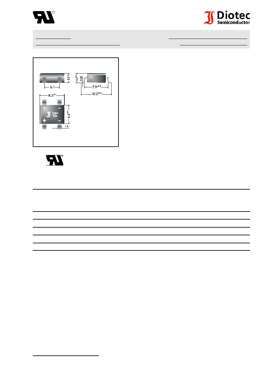
Plastic case SO-DIL
8.3 x 6.4 x 3.1 [mm]
Kunststoffgeh‰use SO-DIL
Weight approx. ≠ Gewicht ca.
0.4 g
Plastic material has UL classification 94V-0
Geh‰usematerial UL94V-0 klassifiziert
Dimensions / Maþe in mm
Standard packaging taped and reeled
see page 18
Standard Lieferform gegurtet auf Rolle siehe Seite 18
Recognized Product ≠ Underwriters Laboratories Inc.Æ File E175067
Anerkanntes Produkt ≠ Underwriters Laboratories Inc.Æ Nr. E175067
Maximum ratings
Grenzwerte
Type
Typ
Alternating input voltage
Eingangswechselspannung
V
VRMS
[V]
Repetitive peak reverse voltage
Periodische Spitzensperrspannung
V
RRM
[V]
1
)
B 40FS
40
80
B 80FS
80
160
B 125FS
125
250
B 250FS
250
600
B 380FS
380
800
Repetitive peak forward current
f > 15 Hz
I
FRM
10 A
2
)
Periodischer Spitzenstrom
Peak forward surge current, 50 Hz half sine-wave
T
A
= 25
/
C
I
FSM
40 A
Stoþstrom f¸r eine 50 Hz Sinus-Halbwelle
Rating for fusing, t < 10 ms
T
A
= 25
/
C
i
2
t
8 A
2
s
Grenzlastintegral, t < 10 ms
Operating junction temperature ≠ Sperrschichttemperatur
T
j
≠ 50...+150
/
C
Storage temperature ≠ Lagerungstemperatur
T
S
≠ 50...+150
/
C
1
) Valid for one branch ≠ G¸ltig f¸r einen Br¸ckenzweig
2
) Valid, if mounted on P.C. board with 25 mm
2
copper pads at each terminal
Dieser Wert gilt bei Montage auf Leiterplatte mit 25 mm
2
Kupferbelag (Lˆtpad) an jedem Anschluþ
2
F:\Data\WP\DatBlatt\Einzelbl‰tter\b40fs-380fs.wpd
B 40FS ... B 380FS
Characteristics
Kennwerte
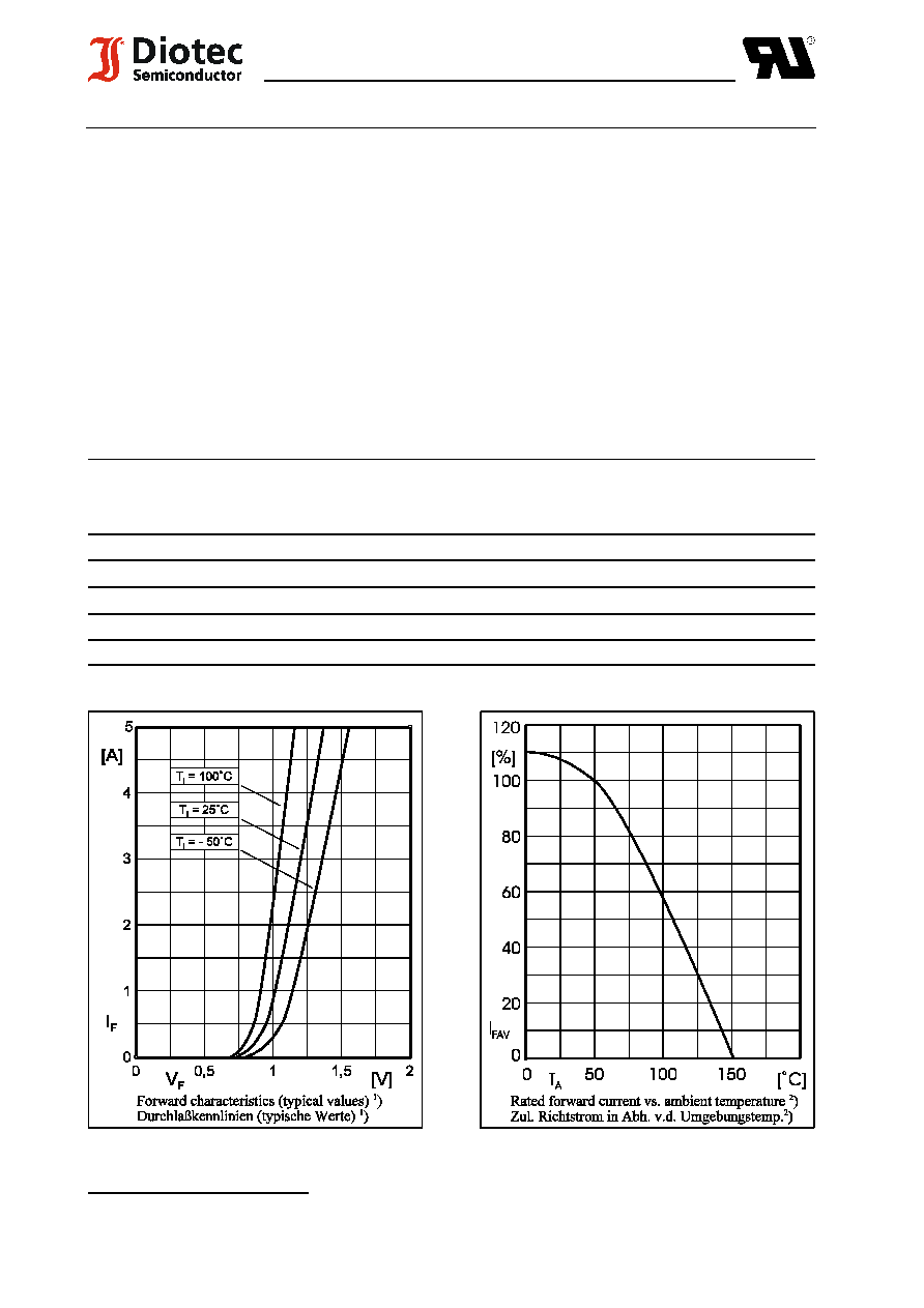
Max. average fwd. rectified current
T
A
= 50
/
C
R-load
I
FAV
1.0 A
2
)
Dauergrenzstrom
C-load
I
FAV
0.8 A
2
)
Forward voltage ≠ Durchlaþspannung
T
j
= 25
/
C
I
F
= 1 A
V
F
< 1.3 V
1
)
Leakage current ≠ Sperrstrom
T
j
= 25
/
C
V
R
= V
RRM
I
R
< 10
:
A
Reverse recovery time
I
F
= 0.5 A through/¸ber
t
rr
< 300 ns
Sperrverzug
I
R
= 1 A to/auf I
R
= 0.25 A
Thermal resistance junction to ambient air
R
thA
< 60 K/W
2
)
W‰rmewiderstand Sperrschicht ≠ umgebende Luft
Type
Typ
Max. admissible load capacitor
Max. zul‰ssiger Ladekondensator
C
L
[
:
F]
Min. required protective resistor
Min. erforderl. Schutzwiderstand
R
t
[
S
]
B 40FS
5000
0.8
B 80FS
2500
1.6
B 125FS
1500
2.5
B 250FS
800
5.0
B 380FS
600
8.0