ChipFind - документация

Электронный компонент: P4KE33A

Скачать:  PDF   ZIP
1
) Non-repetitive current pulse see curve I
PPM
= f (t
r
)
Hchstzulssiger Spitzenwert eines einmaligen Strom-Impulses, siehe Kurve I
PPM
= f (t
r
)
2
) Valid, if leads are kept at ambient temperature at a distance of 10 mm from case
Gltig, wenn die Anschludrhte in 10 mm Abstand von Gehuse auf Umgebungstemperatur gehalten werden
3
) Unidirectional diodes only Nur fr unidirektionale Dioden
1
07.01.2003
P4 KE 6.8 ... P4 KE 440CA
Unidirectional and bidirectional
Unidirektionale und bidirektionale
Transient Voltage Suppressor Diodes
Spannungs-Begrenzer-Dioden
Peak pulse power dissipation
400 W
Impuls-Verlustleistung
Nominal breakdown voltage
6.8...440 V
Nominale Abbruch-Spannung
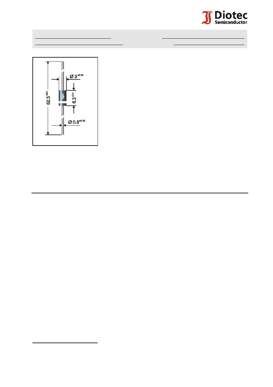
Plastic case Kunststoffgehuse
DO-15 (DO-204AC)
Weight approx. Gewicht ca.
0.4 g
Plastic material has UL classification 94V-0
Gehusematerial UL94V-0 klassifiziert
Dimensions / Mae in mm
Standard packaging taped in ammo pack
see page 16
Standard Lieferform gegurtet in Ammo-Pack
siehe Seite 16
For bidirectional types (suffix "C" or "CA"), electrical characteristics apply in both directions.
Fr bidirektionale Dioden (Suffix "C" oder "CA") gelten die el. Werte in beiden Richtungen.
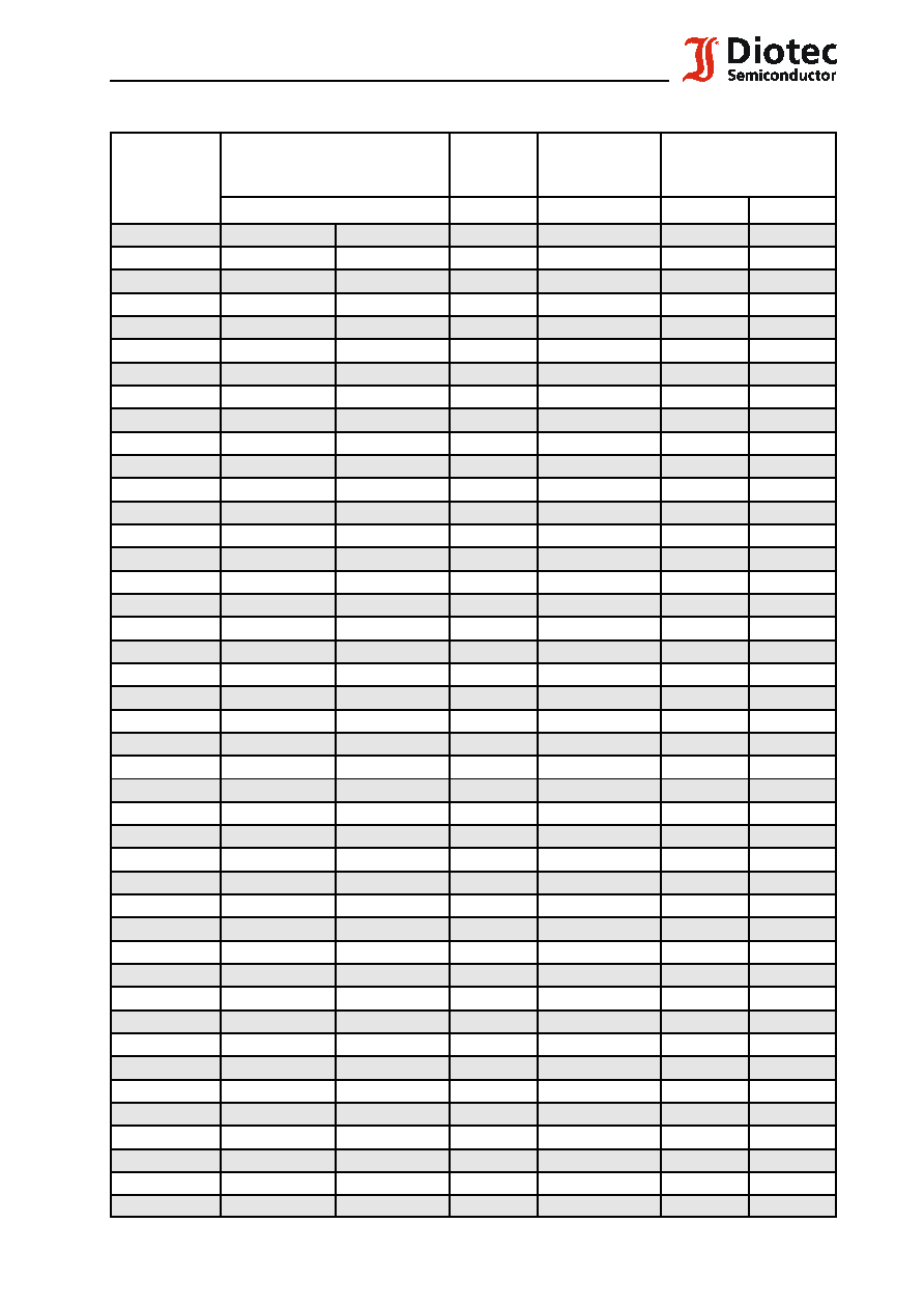
Maximum ratings and Characteristics
Kenn- und Grenzwerte
Peak pulse power dissipation (10/1000
:
s waveform)
T
A
= 25
/
C
P
PPM
400 W
1
)
Impuls-Verlustleistung (Strom-Impuls 10/1000
:
s)
Steady state power dissipation
T
A
= 25
/
C
P
M(AV)
1 W
2
)
Verlustleistung im Dauerbetrieb
Peak forward surge current, 60 Hz half sine-wave
T
A
= 25
/
C
I
FSM
40 A
3
)
Stostrom fr eine 60 Hz Sinus-Halbwelle
Max. instantaneous forward voltage
I
F
= 25 A
V
BR
#
200 V
V
F
< 3.0 V
3
)
Augenblickswert der Durchlaspannung
V
BR
> 200 V
V
F
< 6.5 V
3
)
Operating junction temperature Sperrschichttemperatur
T
j
50...+175
/
C
Storage temperature Lagerungstemperatur
T
S
50...+175
/
C
Thermal resistance junction to ambient air
R
thA
< 45 K/W
2
)
Wrmewiderstand Sperrschicht umgebende Luft
Thermal resistance junction to lead
R
thL
< 15 K/W
Wrmewiderstand Sperrschicht Anschludraht
2
F:\Data\Wp\DatBlatt\Einzelbltter\p4ke.wpd
P4 KE 6.8 ... P4 KE 440CA
Maximum ratings
Grenzwerte
Type
Typ
Breakdown voltage at I
T
= 1 mA
Abbruch-Spanng. bei I
T
= 1 mA
*) at / bei I
T
= 10 mA
Stand-off
voltage
Sperrspg.
Max. rev. current
Max. Sperrstrom
at / bei V
WM
Max. clamping voltage
Max. Begrenzerspanng.
at / bei I
PPM
(10/1000
:
s)
V
BR
[V]
V
WM
[V]
I
D
[
:
A]
V
C
[V]
I
PPM
[A]
P4 KE6.8
6.8 10%
6.12...7.48 *)
5.5
1000
10.8
38.0
P4 KE6.8A
6.8 5%
6.45...7.14 *)
5.8
1000
10.5
40.0
P4 KE7.5
7.5 10%
6.75...8.25 *)
6.0
500
11.7
35.0
P4 KE7.5A
7.5 5%
7.13...7.88 *)
6.4
500
11.3
37.0
P4 KE8.2
8.2 10%
7.38...9.02 *)
6.6
200
12.5
33.0
P4 KE8.2A
8.2 5%
7.79...8.61 *)
7.0
200
12.1
34.0
P4 KE9.1
9.1 10%
8.19...10.0
7.3
50
13.8
30.0
P4 KE9.1A
9.1 5%
8.65...9.55
7.7
50
13.4
31.0
P4 KE10
10 10%
9.0...11.0
8.1
10
15.0
28.0
P4 KE10A
10 5%
9.5...10.5
8.5
10
14.5
29.0
P4 KE11
11 10%
9.9...12.1
8.9
5
16.2
26.0
P4 KE11A
11 5%
10.5...11.6
9.4
5
15.6
27.0
P4 KE12
12 10%
10.8...13.2
9.7
5
17.3
24.0
P4 KE12A
12 5%
11.4...12.6
10.2
5
16.7
25.0
P4 KE13
13 10%
11.7...14.3
10.5
5
19.0
22.0
P4 KE13A
13 5%
12.4...13.7
11.1
5
18.2
23.0
P4 KE15
15 10%
13.5...16.5
12.1
5
22.0
19.0
P4 KE15A
15 5%
14.3...15.8
12.8
5
21.2
21.0
P4 KE16
16 10%
14.4...17.6
12.9
5
23.5
17.8
P4 KE16A
16 5%
15.2...16.8
13.6
5
22.5
18.6
P4 KE18
18 10%
16.2...19.8
14.5
5
26.5
16.0
P4 KE18A
18 5%
17.1...18.9
15.3
5
25.5
16.5
P4 KE20
20 10%
18.0...22.0
16.2
5
29.1
14.0
P4 KE20A
20 5%
19.0...21.0
17.1
5
27.7
15.0
P4 KE22
22 10%
19.8...24.2
17.8
5
31.9
13.0
P4 KE22A
22 5%
20.9...23.1
18.8
5
30.6
13.7
P4 KE24
24 10%
21.6...26.4
19.4
5
34.7
12.0
P4 KE24A
24 5%
22.8...25.2
20.5
5
33.2
12.6
P4 KE27
27 10%
24.3...29.7
21.8
5
39.1
10.7
P4 KE27A
27 5%
25.7...28.4
23.1
5
37.5
11.0
P4 KE30
30 10%
27.0...33.0
24.3
5
43.5
9.6
P4 KE30A
30 5%
28.5...31.5
25.6
5
41.4
10.0
P4 KE33
33 10%
29.7...36.3
26.8
5
47.7
8.8
P4 KE33A
33 5%
31.4...34.7
28.2
5
45.7
9.0
P4 KE36
36 10%
32.4...39.6
29.1
5
52.0
8.0
P4 KE36A
36 5%
34.2...37.8
30.8
5
49.9
8.4
P4 KE39
39 10%
35.1...42.9
31.6
5
56.4
7.4
P4 KE39A
39 5%
37.1...41.0
33.3
5
53.9
7.7
P4 KE43
43 10%
38.7...47.3
34.8
5
61.9
6.7
P4 KE43A
43 5%
40.9...45.2
36.8
5
59.3
7.0
P4 KE47
47 10%
42.3...51.7
38.1
5
67.8
6.2
P4 KE47A
47 5%
44.7...49.4
40.2
5
64.8
6.4
P4 KE51
51 10%
45.9...56.1
41.3
5
73.5
5.7
3
07.01.2003
P4 KE 6.8 ... P4 KE 440CA
Maximum ratings
Grenzwerte
Type
Typ
Breakdown voltage at I
T
= 1 mA
Abbruch-Spanng. bei I
T
= 1 mA
*) at / bei I
T
= 10 mA
Stand-off
voltage
Sperrspg.
Max. rev. current
Max. Sperrstrom
at / bei V
WM
Max. clamping voltage
Max. Begrenzerspanng.
at / bei I
PPM
(10/1000
:
s)
V
BR
[V]
V
WM
[V]
I
D
[
:
A]
V
C
[V]
I
PPM
[A]
P4 KE51A
51 5%
48.5...53.6
43.6
5
70.1
6.0
P4 KE56
56 10%
50.4...61.6
45.4
5
80.5
5.2
P4 KE56A
56 5%
53.2...58.8
47.8
5
77.0
5.4
P4 KE62
62 10%
55.8...68.8
50.2
5
89.0
4.7
P4 KE62A
62 5%
58.9...65.1
53.0
5
85.0
5.0
P4 KE68
68 10%
61.2...74.8
55.1
5
98.0
4.2
P4 KE68A
68 5%
64.6...71.4
58.1
5
92.0
4.5
P4 KE75
75 10%
67.5...82.5
60.7
5
108
3.8
P4 KE75A
75 5%
71.3...78.8
64.1
5
103
4.0
P4 KE82
82 10%
73.8...90.2
66.4
5
118
3.5
P4 KE82A
82 5%
77.9...86.1
70.1
5
113
3.7
P4 KE91
91 10%
81.9...100
73.7
5
131
3.2
P4 KE91A
91 5%
86.5...95.5
77.8
5
125
3.3
P4 KE100
100 10%
90.0...110
81.0
5
144
2.9
P4 KE100A
100 5%
95.0...105
85.5
5
137
3.0
P4 KE110
110 10%
99.0...121
89.2
5
158
2.6
P4 KE110A
110 5%
105...116
94.0
5
152
2.7
P4 KE120
120 10%
108...132
97.2
5
173
2.4
P4 KE120A
120 5%
114...126
102
5
165
2.5
P4 KE130
130 10%
117...143
105
5
187
2.2
P4 KE130A
130 5%
124...137
111
5
179
2.3
P4 KE150
150 10%
135...165
121
5
215
1.9
P4 KE150A
150 5%
143...158
128
5
207
2.0
P4 KE160
160 10%
144...176
130
5
230
1.8
P4 KE160A
160 5%
152...168
136
5
219
1.9
P4 KE170
170 10%
153...187
138
5
244
1.7
P4 KE170A
170 5%
162...179
145
5
234
1.8
P4 KE180
180 10%
162...198
146
5
258
1.6
P4 KE180A
180 5%
171...189
154
5
246
1.7
P4 KE200
200 10%
180...220
162
5
287
1.4
P4 KE200A
200 5%
190...210
171
5
274
1.5
P4 KE220
220 10%
198...242
175
5
344
1.2
P4 KE220A
220 5%
209...231
185
5
328
1.3
P4 KE250
250 10%
225...275
202
5
360
1.1
P4 KE250A
250 5%
237...263
214
5
344
1.2
P4 KE300
300 10%
270...330
243
5
430
0.97
P4 KE300A
300 5%
285...315
256
5
414
1.0
P4 KE350
350 10%
315...385
284
5
504
0.83
P4 KE350A
350 5%
332...368
300
5
482
0.87
P4 KE400
400 10%
360...440
324
5
574
0.73
P4 KE400A
400 5%
380...420
342
5
548
0.76
P4 KE440
440 10%
396...484
356
5
631
0.66
P4 KE440A
440 5%
418...462
376
5
602
0.69
1
) Valid, if leads are kept at ambient temperature at a distance of 10 mm from case
Gltig, wenn die Anschludrhte in 10 mm Abstand von Gehuse auf Umgebungstemperatur gehalten werden
4
F:\Data\Wp\DatBlatt\Einzelbltter\p4ke.wpd
P4 KE 6.8 ... P4 KE 440CA
1
The order of type numbers is graded to the international E 24 standard. The standard tolerance of
the breakdown voltage for each type is 10%. Suffix "A" denotes a tolerance of 5%.
e.g.: P4KE160C = bidirectional diode, V
BR
= 160 V ( 10%), V
WM
$
130 V at I
D
= 5
:
A
P4KE10A = unidirectional diode, V
BR
= 10V ( 5%), V
WM
$
8.1 V at I
D
= 10
:
A
Die Abstufung der Typen innerhalb der Reihe entspricht dem internationalen E 24-Standard. Die
Toleranz der Arbeitsspannung jedes einzelnen Typs betrgt in der Standardausfhrung 10%.
Suffix "A" kennzeichnet eine Toleranz von 5%.
z.B.: P4KE160C = bidirectionale Diode, V
BR
= 160 V ( 10%), V
WM
$
130 V bei I
D
= 5
:
A
P4KE10A = unidirectionale Diode, V
BR
= 10V ( 5%), V
WM
$
8.1 V bei I
D
= 10
:
A