ELH0033G8838001401ZX
July
1992
Rev
H
ELH0033G 883 8001401ZX
Fast Buffer Amplifier
Note All information contained in this data sheet has been carefully checked and is believed to be accurate as of the date of publication however this data sheet cannot be a ``controlled document'' Current revisions if any to these
specifications are maintained at the factory and are available upon your request We recommend checking the revision level before finalization of your design documentation Patent pending
1989 Elantec Inc
Features
Slew rate
1500 V
ms
Output drive
100 mA
Rise and fall times
2 9 ns
Input resistance
10
11
X
Power bandwidth
100 MHz
MIL-STD-883 devices 100%
manufactured in U S A
Advantages
Excellent phase linearity
Driver cables and other
capacitive loads
Wide supply range single or split
Ordering Information
Part No
Temp Range Package Outline
ELH0033G 883B
b
55 C to
a
125 C
TO-8
MDP0002
8001401ZX is the SMD version of this device
Connection Diagram
12-Pin TO-8
0033 ≠ 1
Top View
Note Case is electrically isolated
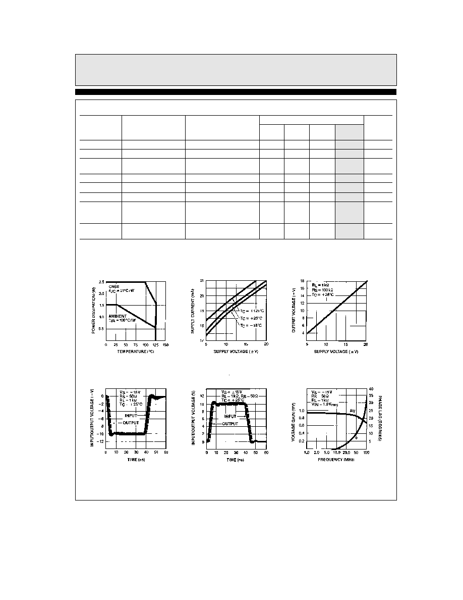
General Description
The ELH0033 is a high-speed FET input voltage follower buff-
er designed to provide high output currents from DC to over
100 MHz The ELH0033 slews at 1500 V
ms and will drive 100X
loads Phase linearity is excellent to 20 MHz allowing the buff-
er to be included in op amp loops
The ELH0033 is intended to fulfill a wide range of buffer appli-
cations such as high-speed line drivers video impedance trans-
formation nuclear instrumentation amplifiers op amp isolation
buffers for driving reactive loads and high impedance input
buffers for high-speed A to D's and comparators
These devices are constructed using specially selected junction
FETs and active laser trimming to achieve guaranteed perform-
ance specifications The ELH0033 is specified for operation
from
b
55 C to
a
125 C
Elantec facilities comply with MIL-I-45208A and other applica-
ble quality specifications Elantec's Military devices are 100%
fabricated and assembled in our rigidly controlled ultra-clean
facilities in Milpitas California For additional information on
Elantec's Quality and Reliability Assurance policy and proce-
dures request brochure QRA-1
Equivalent Schematic
0033 ≠ 2

ELH0033G 883 8001401ZX
Fast Buffer Amplifier
Absolute Maximum Ratings
V
S
Supply Voltage (V
a b
V
b
)
40V
V
IN
Input Voltage
40V
P
D
Power Dissipation (See Curves)
1 5W
I
OC
Continuous Output Current
g
100 mA
I
OP
Peak Output Current
g
250 mA
T
A
Operating Temperature Range
ELH0033
b
55 C to
a
125 C
T
J
Operating Junction Temperature
175 C
T
ST
Storage Temperature
b
65 C to
a
150 C
Lead Temperature
(Soldering 10 seconds)
300 C
Important Note
All parameters having Min Max specifications are guaranteed The Test Level column indicates the specific device testing actually
performed during production and Quality inspection Elantec performs most electrical tests using modern high-speed automatic test
equipment specifically the LTX77 Series system Unless otherwise noted all tests are pulsed tests therefore T
J
e
T
C
e
T
A
Test Level
Test Procedure
I
100% production tested and QA sample tested per QA test plan QCX0002
II
100% production tested at T
A
e
25 C and QA sample tested at T
A
e
25 C
T
MAX
and T
MIN
per QA test plan QCX0002
III
QA sample tested per QA test plan QCX0002
IV
Parameter is guaranteed (but not tested) by Design and Characterization Data
V
Parameter is typical value at T
A
e
25 C for information purposes only
DC Electrical Characteristics
V
S
e
g
15V V
IN
e
0V T
MIN
s
T
A
s
T
MAX
Parameter
Description
Test Conditions
ELH0033
Units
Min
Typ
Max
Test
Level
V
OS
Output Offset
R
S
s
100 k
X
5
10
I
mV
Voltage
T
J
e
25 C (Note 1)
R
S
s
100 k
X
15
I
mV
DV
OS
DT
Average Temperature
Coefficient of
R
S
e
100
X
50
V
mV C
Offset Voltage
I
B
Input Bias Current
T
J
e
25 C (Note 1)
250
I
pA
T
A
e
25 C (Note 2)
2 5
IV
nA
T
J
e
T
A
e
T
MAX
10
I
nA
A
V
Voltage Gain
R
S
e
100
X R
L
e
1 k
X
0 97
0 98
1 00
I
V V
V
IN
e
g
10V
R
IN
Input Impedance
R
L
e
1 k
X
10
10
10
11
IV
X
T
J
e
25 C (Note 1)
10
10
10
11
I
X
R
L
e
1 k
X
R
O
Output Impedance
R
L
e
1 k
X V
IN
e
g
1V
6
10
I
X
V
O
Output Voltage
V
IN
e
g
14V
g
12
I
V
Swing
R
L
e
1 k
X
V
IN
e
g
10 5V
g
9
I
V
R
L
e
100
X T
A
e
25 C
I
S
Supply Current
14 5
20
22
I
mA
Power Consumption
600
660
I
mW
Note 1 Specification is at 25 C junction temperature due to requirements of high-speed automatic testing Actual values at operating
temperature will exceed the value at T
J
e
25 C When supply voltages are
g
15V no-load operating junction temperature
may rise 40 C ≠ 60 C above ambient and more under load conditions Accordingly V
OS
may change one to several mV and I
B
will change significantly during warm-up Refer to I
B
vs temperature graph for expected values
Note 2 Measured in still air 7 minutes after application of power
2
TD
is
34in
ELH0033G 883 8001401ZX
Fast Buffer Amplifier
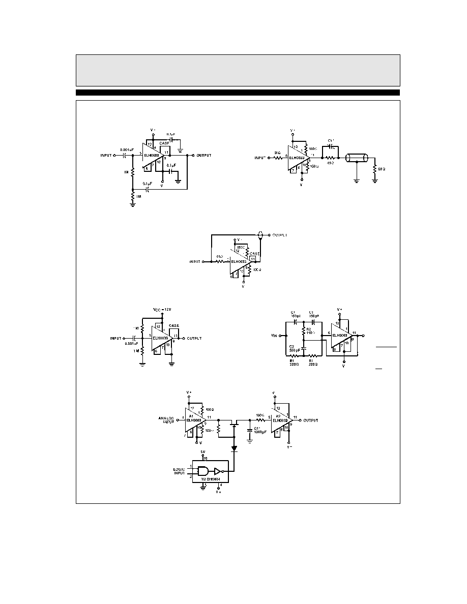
Typical Applications
Contd
High Input Impedance AC Coupled Amplifier
f
H
t
100 MHz
0033 ≠ 8
Coaxial Cable Driver
0033 ≠ 9
Select C1 for optimum pulse response
Instrumentation Shield Line Driver
0033 ≠ 10
Single Supply AC Amplifier
0033 ≠ 11
4 5 MHz Notch Filter
F
O
e
1
2
q
R1C1
R1
e
2 R2
C1
e
C2
2
0033 ≠ 12
High-Speed Sample and Hold
Polycarbon or teflon
0033 ≠ 13
5