 | –≠–ª–µ–∫—Ç—Ä–æ–Ω–Ω—ã–π –∫–æ–º–ø–æ–Ω–µ–Ω—Ç: ELM307 | –°–∫–∞—á–∞—Ç—å:  PDF PDF  ZIP ZIP |
ELM307
Elm Electronics ≠ Circuits for the Hobbyist
< http://www.elmelectronics.com/ >
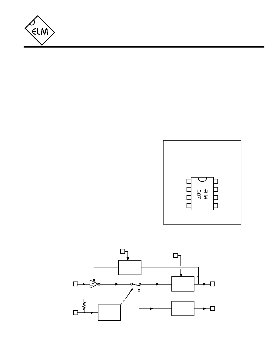
Connection Diagram
PDIP and SOIC
(top view)
V
DD
V
SS
Camera Control
The ELM307 is a retriggerable one-shot circuit
that has been designed for electronically controlling
the shutter of a film or digital still camera. The circuit
provides a variable pulse width timer, a variable
delay reset timer, power control, and an LED status
drive all in an 8 pin package.
In operation, a monitored signal (alarm contact,
audio signal, oscillator signal, etc.) is applied to the
circuit's Trigger input. A low level at this input
immediately causes an output at the Camera pin
(controlling the shutter) that lasts for the duration set
by PW. Further triggering is inhibited until an
additional period (set by Delay) passes, allowing
time for the film to advance or for the digital image to
be stored.
To help with setup, the circuit has a test mode in
which the Camera output is blocked, and the LED is
instead energized. Toggling between the test mode
and the run mode is accomplished with the single
pushbutton input, as is the power on and off.
∑ Low power CMOS design - typically 1mA at 5V
∑ No external timing elements required
∑ Test mode assists with setup
∑ Single pushbutton control
∑ Auto power off saves batteries
∑ LED output shows status
∑ High current drive outputs - up to 25mA
∑ Security camera control
∑ Candid shots of animals or people
∑ Time lapse photography
∑ Remote triggering of cameras
Trigger
LED
Camera
Delay
Description
Applications
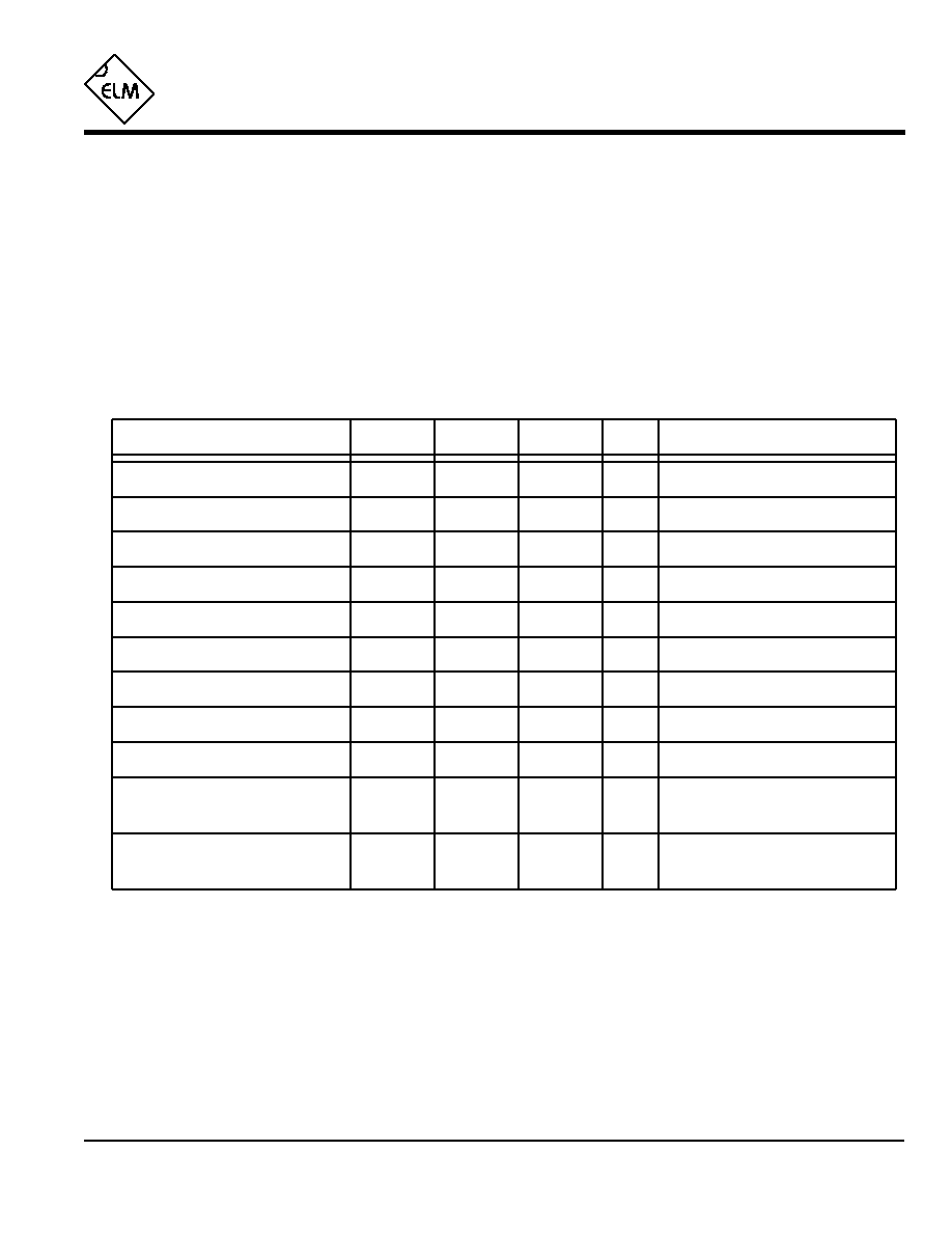
Block Diagram
1 of 4
Features
ELM307DSA
PB
PW
1
2
3
4
8
7
6
5
Trigger
5
7
Pulse
Generator
Camera
4
6
LED
PB
LED
Logic
Delay
Timer
V
DD
Delay
2
PW
3
Control
Logic

ELM307
Elm Electronics ≠ Circuits for the Hobbyist
< http://www.elmelectronics.com/ >
Pin Descriptions
Ordering Information
These integrated circuits are available in either the 300 mil plastic DIP format, or in the 200 mil SOIC surface
mount type of package. To order, add the appropriate suffix to the part number:
300 mil Plastic DIP............................... ELM307P
200 mil SOIC..................................... ELM307SM
2 of 4
All rights reserved. Copyright ©2001 Elm Electronics.
Every effort is made to verify the accuracy of information provided in this document, but no representation or warranty can be
given and no liability assumed by Elm Electronics with respect to the accuracy and/or use of any products or information
described in this document. Elm Electronics will not be responsible for any patent infringements arising from the use of these
products or information, and does not authorize or warrant the use of any Elm Electronics product in life support devices and/or
systems. Elm Electronics reserves the right to make changes to the device(s) described in this document in order to improve
reliability, function, or design.
V
DD
(pin 1)
This pin is the positive supply pin, and should
always be the most positive point in the circuit.
Internal circuitry connected to this pin is used to
provide power on reset of the microprocessor, so
an external reset signal is not required. Refer to the
Electrical Characteristics section for further
information.
Delay (pin 2)
The logic level at this input pin determines the
minimum time between Camera outputs. A high
level sets a nominal delay of 5 seconds while a low
level gives 1/2 of a second. This delay is provided
to ensure that the camera has time to prepare for
the next picture, before another cycle is allowed.
PW (pin 3)
The digital level at this pin sets the pulse width of
the output at Camera (pin 7). When at a logic low
level, the time will nominally be 1/4 of a second,
while a high level provides 1 second.
PB (pin 4)
This input is to be connected to a momentary action
spst pushbutton switch. Holding the switch closed
for more than 5 seconds will cause the power to
toggle on (if off), or off (if presently on). If the switch
is released after 2 seconds, but before 4 seconds
pass, the mode will toggle between run and test.
Power up is always to the test mode.
While the switch is being pressed, the LED output
will pulse briefly every second, to assist in counting
time. Once a command is acknowledged, a long
LED pulse will be provided so that you know a
change is to occur.
Trigger (pin 5)
A low level at this input initiates one cycle of circuit
operation. The use of a schmitt trigger on the input
means there are no restrictions on the rise or fall
time of the waveform.
If no trigger pulse occurs after 8 minutes in the test
mode or 32 minutes in the run mode, the circuit will
automatically power itself off.
LED (pin 6)
This output is periodically driven to a high level to
show the various states. If in the test mode, LED
will output a double pulse every 4 seconds, while in
the run mode, a single output occurs every 8
seconds. A Camera output will always blank the
LED output, so the LED cannot affect the picture.
Camera (pin 7)
This output is used to control the camera's shutter.
Usually a transistor provides the actual interface
between the camera and the ELM307 (see the
Example Applications).
V
SS
(pin 8)
Circuit common is connected to this pin. This is the
most negative point in the circuit.
ELM307DSA
Elm Electronics ≠ Circuits for the Hobbyist
< http://www.elmelectronics.com/ >
ELM307
Electrical Characteristics
Absolute Maximum Ratings
Storage Temperature....................... -65∞C to +150∞C
Ambient Temperature with
Power Applied....................................-40∞C to +85∞C
Voltage on V
DD
with respect to V
SS
............ 0 to +7.5V
Voltage on any other pin with
respect to V
SS
........................... -0.6V to (V
DD
+ 0.6V)
Note:
Stresses beyond those listed here will likely damage
the device. These values are given as a design
guideline only. The ability to operate to these levels
is neither inferred nor recommended.
3 of 4
All values are for operation at 25∞C and a 5V supply, unless otherwise noted. For further information, refer to note 1 below.
Characteristic
Minimum
Typical
Maximum
Conditions
Units
Supply voltage, V
DD
3.0
5.0
5.5
V
V
DD
rate of rise
0.05
V/ms
Average supply current, I
DD
1.0
2.4
mA
Notes:
1. This integrated circuit is produced with a Microchip Technology Inc.'s PIC12C5XX as the core embedded
microcontroller. For further device specifications, and possibly clarification of those given, please refer to the
appropriate Microchip documentation.
2. This spec must be met in order to ensure that a correct power on reset occurs. It is quite easily achieved
using most common types of supplies, but may be violated if one uses a slowly varying supply voltage, as
may be obtained through direct connection to solar cells, or some charge pump circuits.
3. Active current. When powered down, requirements are reduced to much less than 1µA.
4. All internal resistances and oscillators are affected to some extent by both temperature and supply voltage
variations. Timers slow down as voltages are reduced, and speed up as temperatures decrease. The times
shown above will typically be 5% longer for circuits operated at room temperature and a 3V supply.
Input low voltage
V
SS
0.15 V
DD
V
Input high voltage
V
DD
V
0.85 V
DD
Output low voltage
0.6
V
Output high voltage
V
V
DD
- 0.7
Current (sink) = 8.7mA
Current (source) = 5.4mA
see note 2
ELM307DSA
LED Current
8
mA
Output PW
0.26
sec
no resistor, V
DD
= 3V
sec
1.05
pin 3 = L
pin 3 = H
0.85 V
DD
see note 3
Delay after PW
0.52
sec
sec
5.2
pin 2 = L
pin 2 = H
see note 4
"
see note 4
see note 4
Internal pullup resistance (pin 4)
300
500
600
K
"
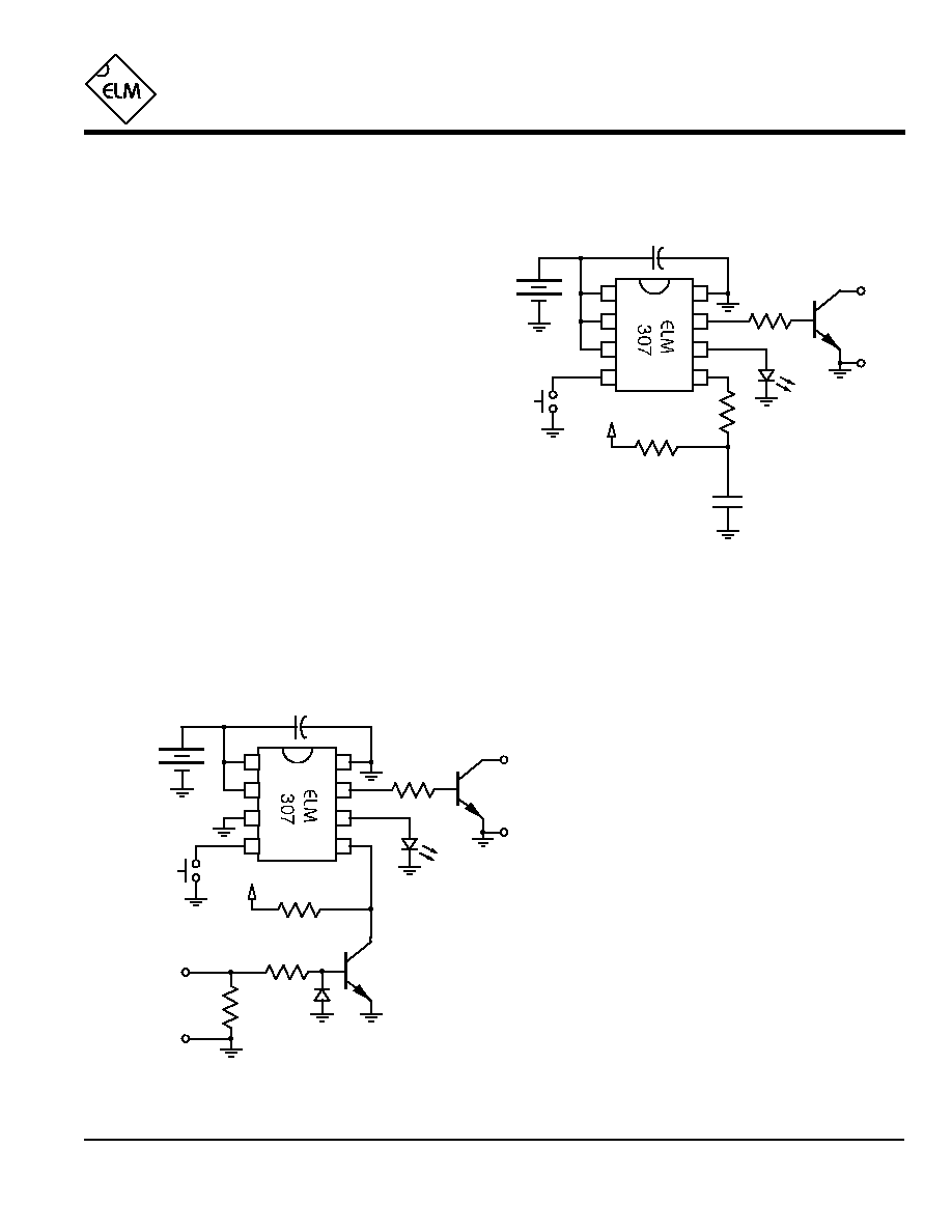
resistor required in series with the LED in this circuit,
as internal circuitry limits the current to a safe value. If
a higher supply level is used, a small value resistor
(220
) should be connected in series with the LED.
The circuit shown in Figure 2 can be used to
capture photos of lightning (as long as the camera's
inherent delay in responding is not so great that the
flash has dissipated). Some cameras have a
considerable delay in opening the shutter after
the button is pressed, and may not be
acceptable for this use.
The circuit shown is virtually identical to that
of figure 1, except that an additional NPN
transistor has been connected to amplify the
output of an AM radio and trigger the circuit.
In operation, the ELM307 is placed in the test
mode, the AM radio is tuned between stations, and its
volume is adjusted to trigger the LED only on lightning
flashes. When ready, the pushbutton is held for 3
seconds then released, switching the circuit to the run
mode. Hopefully the camera is pointing in the right
direction when a flash is detected.
Many variations on these circuits can be used to
trigger a camera, only limited by your imagination.
Why not connect an ELM460 for a 200sec period,
feed it into the ELM307 trigger, then put everything on
a kite and go fly it...
Example Applications
4 of 4
Figures 1 and 2 show two typical circuits that the
ELM307 can be used in. The first is labelled `Party
Camera' but really applies to any candid situation
where a switch is used to initiate the picture being
taken.
Although both circuits show a 3V battery for a
supply, this is only for portability. Any convenient
supply that is between 3V and 5.5V could just as
easily be used. Note that both supplies are bypassed
with 0.1µF capacitors. This is good practice, but could
be eliminated if cost is a concern, and the battery is
electrically close to the ELM307.
In Figure 1, PW and Delay are both at a high
level, so the circuit is configured for a 1 second ouput
with a minimum delay of 5 seconds between outputs.
An NPN transistor (2N3904 or similar) provides the
interface to the camera. Fortunately most cameras
these days (including disposables) use a momentary
contact for the shutter control, and this transistor can
simply be connected across that button to initiate a
picture. You may have to experiment a little to get the
polarity correct, though. An additional 33K
resistor is
shown connected in series with pin 5 to provide some
protection from electrostatic discharges. This is a
good idea if the initiating contact is located more than
a few feet from the ELM307. Note that there is no
ELM307
ELM307DSA
Elm Electronics ≠ Circuits for the Hobbyist
< http://www.elmelectronics.com/ >
Figure 1. Party Camera
Figure 2. Lightning Detector
Camera
shutter
control
1
2
3
4
8
7
6
5
power
33K
+
3V
+3V
0.1µF
33K
AM radio
headphone
output
2.2K
15
33K
1
2
3
4
8
7
6
5
Camera
shutter
control
33K
(see text)
power
33K
+
3V
0.1µF
initiating
contact
+3V