 | –≠–ª–µ–∫—Ç—Ä–æ–Ω–Ω—ã–π –∫–æ–º–ø–æ–Ω–µ–Ω—Ç: ELM320DSC | –°–∫–∞—á–∞—Ç—å:  PDF PDF  ZIP ZIP |
ELM320
Elm Electronics ≠ Circuits for the Hobbyist
< http://www.elmelectronics.com/ >
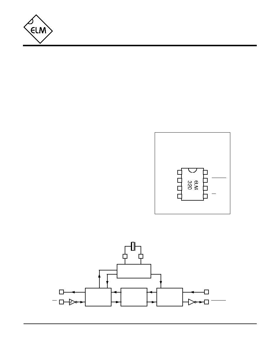
Connection Diagram
PDIP and SOIC
(top view)
V
DD
V
SS
OBD (PWM) to RS232 Interpreter
Since the 1996 model year, North American
automobiles have been required to provide an OBD,
or On Board Diagnostics, port for the connection of
test equipment. Data is transferred serially between
the vehicle and the external equipment using this
connection, in a manner specified by the Society of
Automotive Engineers (SAE) standards. In addition
to operating at different voltage levels, these ports
also use a data format that is not compatible with the
standard used for personal computers.
The ELM320 is an 8 pin integrated circuit that is
able to change the data rate and reformat the OBD
signals into easily recognized ASCII characters. This
allows virtually any personal computer to
communicate with an OBD equipped vehicle using
only a standard serial port and a terminal program.
By also enhancing it with an interface program,
hobbyists can create their own custom scan tool.
This integrated circuit was designed to provide a
cost-effective way for experimenters to work with an
OBD system, so a few features such as RS232
handshaking, variable baud rates, etc., have not
been implemented. In addition, this device is only
able to communicate using the 41.6KHz J1850 PWM
protocol that is commonly used in Ford Motor
Company vehicles.
∑ Low power CMOS design
∑ High current drive outputs - up to 25 mA
∑ Crystal controlled for accuracy
∑ Fully configurable using AT commands
∑ Standard ASCII character output
∑ High speed RS232 communications
∑ 41.6KHz J1850 PWM protocol
∑ Diagnostic trouble code readers
∑ Automotive scan tools
OBDOut
Tx
Description
Applications
Block Diagram
1 of 16
Features
OBDIn
Rx
1
2
3
8
7
6
5
4
XT1
XT2
Tx
RS232
Interface
3.58MHz
2
3
XT1
XT2
Rx
5
6
Timing and
Control
Interpreter
OBD
Interface
OBDOut
4
7
OBDIn
ELM320DSC

ELM320
Elm Electronics ≠ Circuits for the Hobbyist
< http://www.elmelectronics.com/ >
Pin Descriptions
Ordering Information
These integrated circuits are available in either the 300 mil plastic DIP format, or in the 208 mil SOIC surface
mount type of package. To order, add the appropriate suffix to the part number:
300 mil Plastic DIP............................... ELM320P
208 mil SOIC..................................... ELM320SM
2 of 16
All rights reserved. Copyright 2001, 2002, 2003 Elm Electronics.
Every effort is made to verify the accuracy of information provided in this document, but no representation or warranty can be
given and no liability assumed by Elm Electronics with respect to the accuracy and/or use of any products or information
described in this document. Elm Electronics will not be responsible for any patent infringements arising from the use of these
products or information, and does not authorize or warrant the use of any Elm Electronics product in life support devices and/or
systems. Elm Electronics reserves the right to make changes to the device(s) described in this document in order to improve
reliability, function, or design.
V
DD
(pin 1)
This pin is the positive supply pin, and should
always be the most positive point in the circuit.
Internal circuitry connected to this pin is used to
provide power on reset of the microprocessor, so
an external reset signal is not required. Refer to
the Electrical Characteristics section for further
information.
XT1 (pin 2) and XT2 (pin 3)
A 3.579545 MHz NTSC television colourburst
crystal is connected between these two pins.
Crystal loading capacitors (typically 27pF) will
also normally be connected between each of the
pins and the circuit common (Vss).
OBDIn (pin 4)
The OBD data is input to this pin, with a high
logic level representing the active state (and a
low, the passive). No Schmitt trigger input is
provided, so the OBD signal should be buffered
to minimize transition times for the internal
CMOS circuitry. The external level shifting
circuitry is usually sufficient to accomplish this ≠
see the Example Application section for a typical
circuit.
Rx (pin 5)
The computer's RS232 transmit signal can be
directly connected to this pin from the RS232
line as long as a current limiting resistor
(typically about 47K
) is installed in series.
(Internal protection diodes will pass the input
currents safely to the supply connections,
protecting the ELM320.) Internal signal inversion
and Schmitt trigger waveshaping provide the
necessary signal conditioning.
Tx (pin 6)
The RS232 data output pin. The signal level is
compatible with most interface ICs, and there is
sufficient current drive to allow interfacing using
only a single PNP transistor, if desired.
OBDOut (pin 7)
This is the active low output signal which is used
to drive the OBD bus to its active state. Since the
J1850 PWM standard requires a differential bus
signal, the user must create the complement of
this signal to drive the other bus line. See the
Example Application section for more details.
V
SS
(pin 8)
Circuit common is connected to this pin. This is
the most negative point in the circuit.
ELM320DSC
Elm Electronics ≠ Circuits for the Hobbyist
< http://www.elmelectronics.com/ >
ELM320
Electrical Characteristics
Absolute Maximum Ratings
Storage Temperature....................... -65∞C to +150∞C
Ambient Temperature with
Power Applied....................................-40∞C to +85∞C
Voltage on V
DD
with respect to V
SS
............ 0 to +7.5V
Voltage on any other pin with
respect to V
SS
........................... -0.6V to (V
DD
+ 0.6V)
Note:
Stresses beyond those listed here will likely damage
the device. These values are given as a design
guideline only. The ability to operate to these levels
is neither inferred nor recommended.
3 of 16
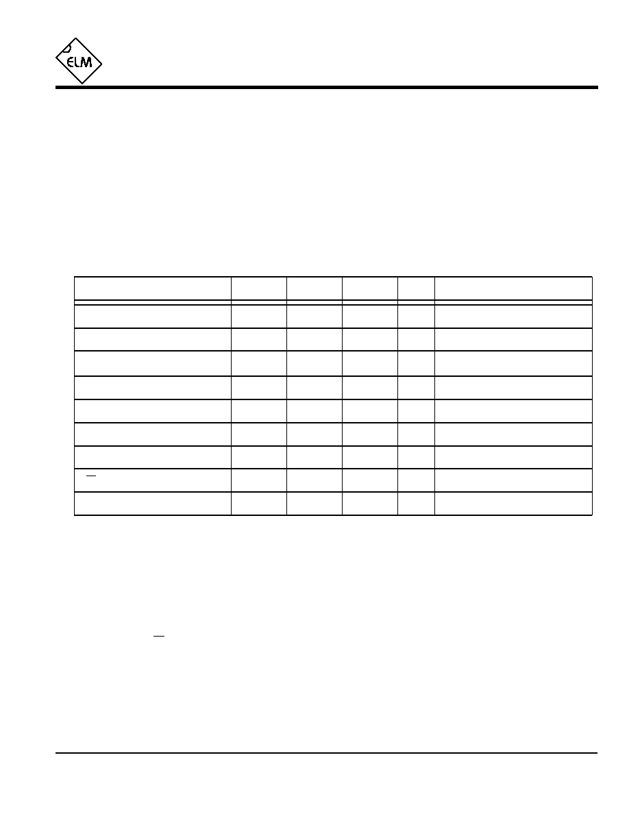
All values are for operation at 25∞C and a 5V supply, unless otherwise noted. For further information, refer to note 1 below.
Characteristic
Minimum
Typical
Maximum
Conditions
Units
Supply voltage, V
DD
4.5
5.0
5.5
V
V
DD
rate of rise
0.05
V/ms
Average supply current, I
DD
1.0
2.4
mA
Notes:
1. This integrated circuit is produced with a Microchip Technology Inc.'s PIC12C5XX as the core embedded
microcontroller. For further device specifications, and possibly clarification of those given, please refer to the
appropriate Microchip documentation (available at http://www.microchip.com/).
2. This spec must be met in order to ensure that a correct power on reset occurs. It is quite easily achieved
using most common types of supplies, but may be violated if one uses a slowly varying supply voltage, as
may be obtained through direct connection to solar cells, or some charge pump circuits.
3. Device only. Does not include any load currents.
4. This specification represents the current flowing through the protection diodes when applying large voltages
to the Rx input (pin 5) through a current limiting resistance. Currents quoted are the maximum that should be
allowed to flow continuously.
5. Nominal data transfer rate when a 3.58 MHz crystal is used as the frequency reference. Data is transferred
to and from the ELM320 with 8 data bits, no parity, and 1 stop bit (8 N 1).
Input low voltage
V
SS
0.15 V
DD
V
Input high voltage
V
DD
V
0.85 V
DD
Output low voltage
0.6
V
Output high voltage
V
V
DD
- 0.7
Current (sink) = 8.7mA
Current (source) = 5.4mA
see note 2
ELM320DSC
see note 3
Rx pin input current
mA
see note 4
-0.5
RS232 baud rate
baud
see note 5
9600
+0.5

4 of 16
ELM320
ELM320DSC
Elm Electronics ≠ Circuits for the Hobbyist
< http://www.elmelectronics.com/ >
Overview
The ELM320 relies on a standard RS232 type
serial connection to communicate with the user. The
data rate is fixed at 9600 baud, with 8 data bits, no
parity bit, 1 stop bit, and no handshaking (often
referred to as 9600 8N1). All responses from the IC
are terminated with a single carriage return character
and, by default, a line feed character as well. Make
sure your software is configured properly for the mode
you have chosen.
Properly connected and powered, the ELM320 will
initially display the message:
ELM320 v2.0
>
In addition to identifying the version of the IC,
receipt of this string is a convenient way to be sure
that the computer connections and the settings are
correct. However, at this point no communications
have taken place with the vehicle, so the state of that
connection is still unknown.
The `>' character displayed above is the ELM320's
prompt character. It indicates that the device is in its
idle state, ready to receive characters on the RS232
port. Characters sent from the computer can either be
intended for the ELM320's internal use, or for
reformatting and passing on to the vehicle's OBD bus.
Commands for the ELM320 are distinguished from
those to the vehicle by always beginning with the
characters `AT' (as is common with modems), while
commands for the OBD bus must contain only the
ASCII characters for hexadecimal digits (0 to 9 and A
to F). This allows the ELM320 to quickly determine
where the received characters are to be directed.
Whether an `AT' type internal command or a hex
string for the OBD bus, all messages to the ELM320
must be terminated with a carriage return character
(hex `0D') before it will be acted upon. The one
exception is when an incomplete string is sent and no
carriage return appears. In this case, an internal timer
will automatically abort the incomplete message after
about 10 seconds, and the ELM320 will print a single
question mark to show that the input was not
understood (and was ignored).
Messages that are misunderstood by the ELM320
(syntax errors) will always be signalled by a single
question mark (`?'). These include incomplete
messages, invalid hexadecimal digit strings, or
incorrect AT commands. It is not an indication of
whether or not the message was understood by the
vehicle. (The ELM320 is a protocol interpreter that
makes no attempt to assess OBD messages for
validity ≠ it only ensures that an even number of hex
digits were received, combined into bytes, and sent
out the OBD port, so it cannot determine if the
message sent to the vehicle is in error.)
Incomplete or misunderstood messages can also
occur if the controlling computer attempts to write to
the ELM320 before it is ready to accept the next
command (as there are no handshaking signals to
control the data flow). To avoid a data overrun, users
should always wait for the prompt character (`>')
before issuing the next command.
Finally, a few convenience items to note. The
ELM320 is not case-sensitive, so `ATZ' is equivalent to
`atz', and to `AtZ'. The device ignores space characters
as well as control characters (tab, linefeed, etc.) in the
input, so they can be inserted anywhere to improve
readability and, finally, issuing only a single carriage
return character will repeat the last command (making
it easier to request updates on dynamic data such as
engine rpm).
Communicating with the ELM320
The following describes how to use the ELM320 to
obtain a great deal of information from your vehicle. To
many, the quantity of information will be overwhelming,
and to others it is not nearly enough.
We begin by discussing just how to talk to the IC,
then how to adjust some options through the use of
`AT' commands, and finally go on to actually talk to the
vehicle, obtaining trouble codes and resetting them.
For the more advanced experimenters, there are also
sections on how to use some of the programmable
features of this product as well.
It is not as daunting as it first appears. Many users
will never need to issue an `AT' command, adjust
timeouts or change the headers. For most, all that is
required is a PC or a PDA with a terminal program
(such as HyperTerminal or ZTerm), and knowledge of
one or two OBD commands, which we provide in the
following...

5 of 16
ELM320
ELM320DSC
Elm Electronics ≠ Circuits for the Hobbyist
< http://www.elmelectronics.com/ >
AT Commands
Several parameters within the ELM320 can be
adjusted in order to modify its behaviour. These do not
normally have to be changed before attempting to talk
to the vehicle, but occasionally the user may wish to
customize the settings, for example by turning the
character echo off, adjusting the timeout value, or
changing the header addresses. In order to do this,
internal `AT' commands must be issued.
Those familiar with PC modems will immediately
recognize AT commands as a standard way in which
modems are internally configured. The ELM320 uses
essentially the same method, always watching the
data sent by the PC, looking for messages that begin
with the character `A' followed by the character `T'. If
found, the next characters will be interpreted as
internal configuration or `AT' commands, and will be
executed upon receipt of a terminating carriage return
character. The ELM320 will reply with the characters
`OK' on the successful completion of a command, so
the user knows that it has been executed.
Some of the following commands allow passing
numbers as arguments in order to set the internal
values. These will always be hexadecimal numbers
which must be provided in pairs. The hexadecimal
conversion chart in the next section may prove useful
if you wish to interpret the values. Also, one should be
aware that for the on/off types of commands, the
second character is a number (1 or 0), the universal
terms for on and off, respectively.
The following is a summary of all of the AT
commands that are recognized by the current version
of the ELM320, sorted alphabetically. Users of
previous versions of this product (v1.x) should note
that their ICs will only support the E, H and Z options.
AR
[ Automatically set the Receive address ]
Responses from the vehicle will be acknowledged
and displayed by the ELM320, if its internally stored
receive address matches the address that the
message is being sent to. With the auto receive
mode in effect, the value used for the receive
address will be chosen based on the current header
bytes, and will automatically be updated whenever
the header bytes are changed.
The value that is used for the receive address is
determined based on the contents of the first header
byte. If it shows that the message uses physical
addressing, the third header byte of the header is
used for the receive address, otherwise (for
functional addressing) the second header byte,
increased in value by 1, will be used. Auto Receive
is turned on by default.
D
[ set all to Defaults ]
This command is used to set the E, H, L, and R
options to their default (or factory) settings, as when
power is first applied. Additionally, the Auto Receive
mode (AR) will be selected, data will be transmitted
in the standard formatted way (as if chosen by FD),
the `NO DATA' timeout will be set to its default value,
and the header bytes will be set to the proper values
for the OBDII operation.
E0 and E1
[ Echo off (0) or on(1) ]
These commands control whether or not characters
received on the RS232 port are retransmitted (or
echoed) back to the host computer. To reduce traffic
on the RS232 bus, users may wish to turn echoing
off by issuing ATE0. The default is E1 (echo on).
FD
[ send Formatted Data ]
This command requests that all responses be
returned as standard ASCII characters which are
readable on virtually any standard terminal program.
Hex digits are shown as two ASCII characters, and
spaces are provided between each byte as a
separator. Also, every line will end with a carriage
return character and (optionally) a linefeed
character, ensuring that every response appears on
a new line. This is the default mode.
H0 and H1
[ Headers off (0) or on(1) ]
These commands control whether or not the header
information is shown in the responses. All OBD
messages have an initial (header) string of three
bytes and a trailing check digit which are normally
not displayed by the ELM320. To see this extra
information, users can turn the headers on by
issuing an ATH1. The default is H0 (headers off).