 | –≠–ª–µ–∫—Ç—Ä–æ–Ω–Ω—ã–π –∫–æ–º–ø–æ–Ω–µ–Ω—Ç: ELM331P | –°–∫–∞—á–∞—Ç—å:  PDF PDF  ZIP ZIP |
ELM331
Elm Electronics ≠ Circuits for the Hobbyist
< http://www.elmelectronics.com/ >
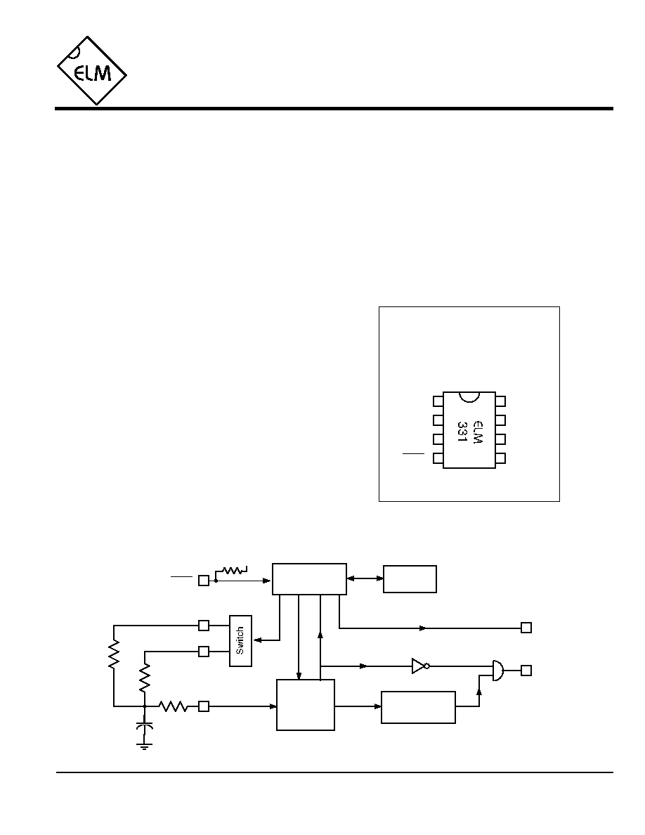
Connection Diagram
PDIP and SOIC
(top view)
V
DD
V
SS
1
2
3
4
8
7
6
5
Solid State Thermostat
The ELM331 is a complete temperature
measurement and control system in an 8 pin
package.
This integrated circuit is designed to compare
two resistances and drive an output pin depending
on the relative value of each. Typically, one of the
resistors will be an NTC thermistor, and the other
one will be a temperature independent resistor
(whether fixed or variable). When the magnitude of
the resistance connected to pin 2 exceeds the value
of the resistance connected to pin 3, the output pin
will be driven to a high state. Hysteresis maintains
the output in that state until the relative values differ
by approximately 8% (or typically 2∞C for a 10K
thermistor).
To reduce the possibility of sporadic outputs, a
condition must exist for three successive cycles, or 6
seconds, before the output pin can change state.
∑ Low power CMOS design - typically 1mA at 5V
∑ Wide supply range - 3.0 to 5.5 volt operation
∑ Built-in proportional hysteresis
∑ Measurement in progress output
∑ Time delay on operate improves noise immunity
∑ Internal pullup resistor on the reset input
∑ High current drive outputs - up to 25 mA
∑ Primary thermostat in temperature control
systems
∑ Staging control for auxiliary heating or cooling
installations
∑ Under or over temperature alarms
2
3
4
6
7
R
1
R
2
Analog to
Digital
Converter
5
Control
Watchdog
Timer
Cap
MIP
Out
R
1
R
2
reset
3 Consecutive
Measurements
Measurement in Progress (busy)
Overrange
V
DD
Out
MIP
R
1
> R
2
reset
Description
Applications
Block Diagram
1 of 4
Features
ELM331DSB

ELM331
Elm Electronics ≠ Circuits for the Hobbyist
< http://www.elmelectronics.com/ >
Pin Descriptions
Ordering Information
These integrated circuits are available in either the 300 mil plastic DIP format, or in the 200 mil SOIC surface
mount type of package. To order, add the appropriate suffix to the part number:
300 mil Plastic DIP............................... ELM331P
200 mil SOIC..................................... ELM331SM
2 of 4
All rights reserved. Copyright ©1999 Elm Electronics.
Every effort is made to verify the accuracy of information provided in this document, but no representation or warranty can be
given and no liability assumed by Elm Electronics with respect to the accuracy and/or use of any products or information
described in this document. Elm Electronics will not be responsible for any patent infringements arising from the use of these
products or information, and does not authorize or warrant the use of any Elm Electronics product in life support devices and/or
systems. Elm Electronics reserves the right to make changes to the device(s) described in this document in order to improve
reliability, function, or design.
V
DD
(pin 1)
This pin is the positive supply pin, and should
always be the most positive point in the circuit.
Internal circuitry connected to this pin is used to
provide power on reset of the microprocessor, so
an external reset signal is normally not required.
Refer to the Electrical Characteristics section for
further information.
R
1
(pin 2)
One of the two resistance input pins. A
temperature dependent resistance is usually
connected to this input for heating or under-
temperature alarm type applications. When the
value of this resistor is greater than the value of
the resistance connected to pin 3 (for three
successive measurements) the output will be
driven high.
R
2
(pin 3)
The reference resistance is connected to this pin
for heating applications, and the temperature
dependent resistance is connected here for
cooling applications. The other end of this resistor
is connected to the integrating capacitor.
reset (pin 4)
The active low reset input. An internal pullup
resistor is provided for convenience. If unused,
this pin may be connected to V
DD
or left open.
Cap (pin 5)
Temperature measurements are made by
determining the time to charge and discharge this
integrating capacitor. Pin 5 forces the capacitor to
a known voltage for these measurements though,
resulting in large current flows. To limit these
capacitor currents, and protect the ELM331, a
series resistor must be connected to this pin. The
value of the resistance, and of the capacitance, is
not critical to the measurements.
MIP (pin 6)
This pin provides a logic high level output while
the ELM331 is busy (measurements are in
progress). It is suitable for directly driving an LED
through a current limiting resistor. As a warning,
this output pulses rapidly if either resistor input is
found to be open circuited.
Out (pin 7)
The output pin assumes a logic high state once
the resistance of R
1
exceeds that of R
2
for three
successive measurement cycles. The output is
maintained until R
1
is less than R
2
by the
hysteresis amount for an additional three counts.
V
SS
(pin 8)
Circuit common is connected to this pin. This is
the most negative point in the circuit.
ELM331DSB
Elm Electronics ≠ Circuits for the Hobbyist
< http://www.elmelectronics.com/ >
ELM331
Electrical Characteristics
Absolute Maximum Ratings
Storage Temperature....................... -65∞C to +150∞C
Ambient Temperature with
Power Applied....................................-40∞C to +85∞C
Voltage on V
DD
with respect to V
SS
............ 0 to +7.5V
Voltage on any other pin with
respect to V
SS
........................... -0.6V to (V
DD
+ 0.6V)
Note:
Stresses beyond those listed here will likely damage
the device. These values are given as a design
guideline only. The ability to operate to these levels
is neither inferred nor recommended.
3 of 4
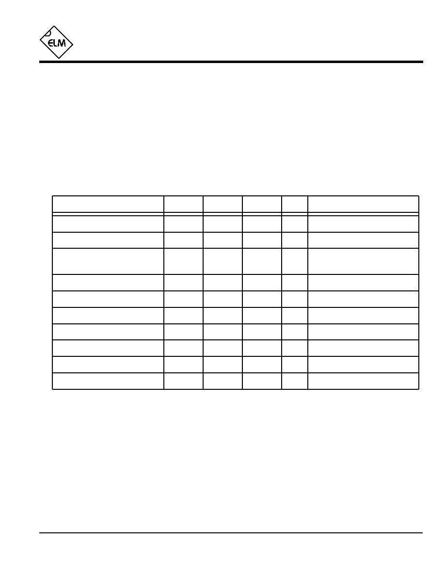
All values are for operation at 25∞C and a 5V supply, unless otherwise noted. For further information, refer to note 1 below.
Characteristic
Minimum
Typical
Maximum
Conditions
Units
Supply Voltage, V
DD
3.0
5.0
5.5
V
V
DD
rate of rise
0.05
V/ms
Average Supply Current, I
DD
1.0
2.4
mA
V
DD
= 5V, see note 3
V
DD
= 3V, see note 3
0.6
2.4
mA
Notes:
1. This integrated circuit is produced with a Microchip Technology Inc.'s PIC12C5XX as the core embedded
microcontroller. For further device specifications, and possibly clarification of those given, please refer to the
appropriate Microchip documentation.
2. This spec must be met in order to ensure that a correct power on reset occurs. It is quite easily achieved
using most common types of supplies, but may be violated if one uses a slowly varying supply voltage, as
may be obtained through direct connection to solar cells, or some charge pump circuits.
3. Device only. Does not include any LED or drive currents.
4. If a measured resistance is determined to be out of limits, the frequency of measurements is increased to
provide visual feedback as well as a faster recovery.
5. The value of the pullup resistance is supply and temperature dependent.
6. One should also maintain R
1
and
R
2
to not less than about 5K
. When C is chosen, select the pin 5 current
limiting resistance so that R
LIM
C is less than 1msec, and R
LIM
is greater than 1K
.
Frequency of measurements
2.0
sec
see note 4
Input low voltage - reset pin
V
SS
0.15 V
DD
V
Input high voltage - reset pin
V
DD
V
0.85 V
DD
Output low voltage
0.6
V
Output high voltage
V
V
DD
- 0.7
Current (sink) = 8.7mA
Current (source) = 5.4mA
Reset pin internal pullup resistance
300
470
600
K
see note 5
R
1
C
or
R
2
C time constant
500
500,000
µs
see note 6
see note 2
ELM331DSB
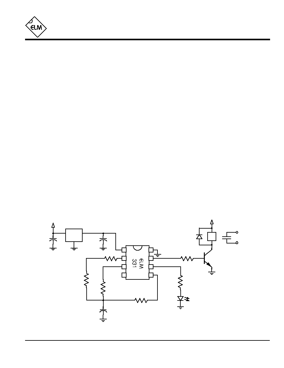
Example Application
4 of 4
Figure 1. Backup Heating Control Thermostat
Figure 1 shows the ELM331 in an example heating
control circuit. A closed contact output occurs
whenever the temperature measured by R
TEMP
falls to
a value less than that determined by R
SET
. It is
anticipated that this type of circuit could possibly be
used to control temperatures over the range of -40∞C
to +40∞C.
Power for the circuit is from a 12V supply, that is
reduced to 5V by the 78L05 regulator. This gives a
stable supply voltage for the ELM331, as well as
convenient voltage for use with a standard relay coil.
The type of relay is not important, as long as
consideration is given to its coil requirements, and the
capabilities of the ELM331. In this example, a relay
with a 400
coil resistance was chosen so that a
2N3904 could drive it directly.
Temperature measuring is performed by R
TEMP
,
which is a negative temperature coefficient type
thermistor. It has a resistance of 10K
at 25∞C, and
this value decreases with increasing temperature. This
value was chosen both because it is commonly
available, and because it limits the 0.1µF integrating
capacitor currents to less than 1mA over the typical
range of operation (keeping the thermistor self-heating
to a minimum).
If the thermistor is mounted any appreciable
distance from the ELM331, consideration must be
given to cabling effects such as capacitive and induced
currents. Generally the integrated circuit can be
adequately protected by mounting a small value (220
)
resistor physically close to the ELM331 as shown
below. Take into account it's value when determining
the setpoint, though.
For this design, R
SET
was selected to be equal to
the resistance of R
TEMP
at 10∞C, so that the relay
contact closes for any measured temperatures less
than 10∞C. The resistance value was determined from
specs given by the manufacturer, but could have been
determined experimentally as well.
An LED has been provided for visual feedback of
the circuit operation. It is connected to the
`measurement in progress' output, so that it is
energized each time a measurement is being made.
Typically, this would be for about 25mS every 2
seconds.
Variations on this circuit could easily be made...
Simply by reversing R
SET
and R
TEMP
, one obtains a
cooling control thermostat... Rather than a relay output,
the circuit could have been connected directly to other
logic circuits. The measurement in progress pin could
then be used either as an interrupt, or as a busy flag
that can clock in new results on it's falling edge...
Battery backup is another option that could be
added to this circuit, but then consideration should be
given to using the ELM341 Low Power Thermostat...
ELM331
ELM331DSB
Elm Electronics ≠ Circuits for the Hobbyist
< http://www.elmelectronics.com/ >
2.2K
560
10K
R
SET
R
TEMP
0.1µF
78L05
2N3904
LED
18K
10K
@25∞C
1N4001
To the
heating
control
0.1µF
+12V
+12V
0.1µF
1
2
3
4
8
7
6
5
12V Relay
see text