 | –≠–ª–µ–∫—Ç—Ä–æ–Ω–Ω—ã–π –∫–æ–º–ø–æ–Ω–µ–Ω—Ç: ELM337SM | –°–∫–∞—á–∞—Ç—å:  PDF PDF  ZIP ZIP |
ELM337
Elm Electronics ≠ Circuits for the Hobbyist
< http://www.elmelectronics.com/ >
Connection Diagram
PDIP and SOIC
(top view)
V
DD
V
SS
1
2
3
4
8
7
6
5
Light Switch
The ELM337 provides a convenient means to
interface standard photocells or light dependent
resistors (LDRs) to digital logic circuits. It provides
an input comparator with hysteresis, line frequency
filtering, digital delays, and high current output
drivers all within the one 8 pin package.
Three mode setting pins configure the ELM337
for pulse or continuous output and for a delay on
change of from 1 msec to 10 minutes. The transition
threshold is set with a single external resistor,
simplifying designs and minimizing costs.
Applications need not be limited to those
employing photocells, as the Example Applications
section shows. The Schmitt trigger input provides a
convenient way to interface to virtually any input
signal, whether from digital logic or from a slowly
varying analog source. The remainder of the
ELM337 can simply be thought of as a time delay on
pickup and dropout type circuit - very useful for
sequencing processes.
∑ Low power CMOS design - typically 1mA at 5V
∑ Operates from 3V to 5.5V
∑ No external timing elements required
∑ Low parts count
∑ Digitally selected delays of up to 10 minutes
∑ Pulsed or continuous outputs
∑ Internal line frequency filtering
∑ High current drive outputs - up to 25 mA
∑ Automatic lighting controls
∑ Security light beam monitoring
∑ Position sensing
∑ Light controlled counters
∑ Time delay circuits
LDR
Dark
Light
M2
Description
Applications
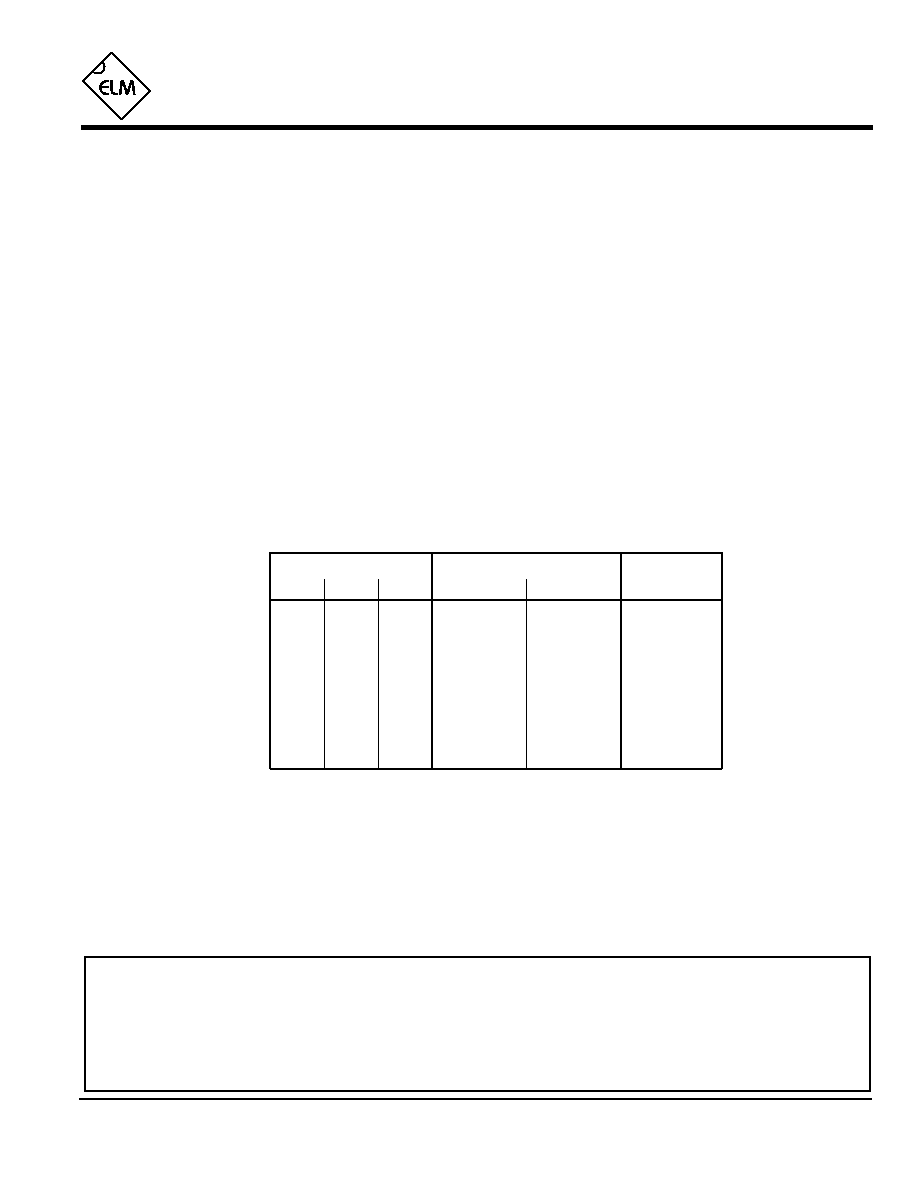
Block Diagram
1 of 4
Features
ELM337DSA
M0
M1
LDR
5
7
6
Programmable
Timer
Output
Logic
Light
Dark
4
M0
3
M1
2
M2
Line
Frequency
Detector
ELM337
Elm Electronics ≠ Circuits for the Hobbyist
< http://www.elmelectronics.com/ >
Pin Descriptions
Ordering Information
These integrated circuits are available in either the 300 mil plastic DIP format, or in the 200 mil SOIC surface
mount type of package. To order, add the appropriate suffix to the part number:
300 mil Plastic DIP............................... ELM337P
200 mil SOIC..................................... ELM337SM
2 of 4
All rights reserved. Copyright ©2000 Elm Electronics.
Every effort is made to verify the accuracy of information provided in this document, but no representation or warranty can be
given and no liability assumed by Elm Electronics with respect to the accuracy and/or use of any products or information
described in this document. Elm Electronics will not be responsible for any patent infringements arising from the use of these
products or information, and does not authorize or warrant the use of any Elm Electronics product in life support devices and/or
systems. Elm Electronics reserves the right to make changes to the device(s) described in this document in order to improve
reliability, function, or design.
V
DD
(pin 1)
This pin is the positive supply pin, and should
always be the most positive point in the circuit.
Internal circuitry connected to this pin is used to
provide power on reset of the microprocessor, so
an external reset signal is not required. Refer to the
Electrical Characteristics section for further
information.
M2 (pin 2), M1 (pin 3) and M0 (pin 4)
The digital levels at these pins determine the mode
of operation, as shown in Table 1 below. Levels are
read whenever the LDR input signal changes, so
that modes can be changed `on the fly'.
LDR (pin 5)
This is the voltage sensing input pin. It uses Schmitt
trigger circuitry, and a peak detecting circuit for line
frequency filtering so that slowly varying and
pulsating signals will not cause circuit instability. A
logic low level on this pin will be interpreted as the
presence of light, while a logic high results in a dark
input. See the Example Applications section for
typical connections.
Dark (pin 6) and Light (pin 7)
These are the two active high circuit outputs.
Depending on the mode selected, they will either
remain continually active, or provide a 50 msec
pulse output on change from light to dark (Dark
output) or dark to light (Light output).
V
SS
(pin 8)
Circuit common is connected to this pin. This is the
most negative point in the circuit.
ELM337DSA
Table 1. Modes of Operation
Mode Inputs
Delay on Transition to
M1
L
L
H
H
L
H
L
H
M2
L
L
L
L
H
H
H
H
Dark
50 msec
1 msec
50 msec
50 msec
10 sec
10 sec
10 min
10 min
M0
L
H
L
H
L
H
L
H
Type of
Output
Pulse
Continuous
Continuous
Continuous
Pulse
Continuous
Pulse
Continuous
Light
50 msec
1 msec
50 msec
50 msec
10 sec
10 sec
10 min
10 min

Elm Electronics ≠ Circuits for the Hobbyist
< http://www.elmelectronics.com/ >
ELM337
Electrical Characteristics
Absolute Maximum Ratings
Storage Temperature....................... -65∞C to +150∞C
Ambient Temperature with
Power Applied....................................-40∞C to +85∞C
Voltage on V
DD
with respect to V
SS
............ 0 to +7.5V
Voltage on any other pin with
respect to V
SS
........................... -0.6V to (V
DD
+ 0.6V)
Note:
Stresses beyond those listed here will likely damage
the device. These values are given as a design
guideline only. The ability to operate to these levels
is neither inferred nor recommended.
3 of 4
All values are for operation at 25∞C and a 5V supply, unless otherwise noted. For further information, refer to note 1 below.
Characteristic
Minimum
Typical
Maximum
Conditions
Units
Supply voltage, V
DD
3.0
5.0
5.5
V
V
DD
rate of rise
0.05
V/ms
Average supply current, I
DD
1.0
2.4
mA
Notes:
1. This integrated circuit is produced with a Microchip Technology Inc.'s PIC12C5XX as the core embedded
microcontroller. For further device specifications, and possibly clarification of those given, please refer to the
appropriate Microchip documentation.
2. This spec must be met in order to ensure that a correct power on reset occurs. It is quite easily achieved
using most common types of supplies, but may be violated if one uses a slowly varying supply voltage, as
may be obtained through direct connection to solar cells, or some charge pump circuits.
3. As with all of the delays, the Pulse timing is generated internally, and is affected by both temperature and
supply voltage. Variations are generally less than 5% of this value over the operating range.
Input low voltage
V
SS
0.15 V
DD
V
Input high voltage
V
DD
V
0.85 V
DD
Output low voltage
0.6
V
Output high voltage
V
V
DD
- 0.7
Current (sink) = 8.7mA
Current (source) = 5.4mA
see note 2
ELM337DSA
Output pulse width
50
msec
LDR input threshold
voltages
2.8
V
see note 3
4.25
V
1.3
to dark
to light
0.75
0.85 V
DD
Mode pins
Mode pins

Example Applications
4 of 4
Figure 1 at right shows the ELM337 installed in a
typical lighting control circuit. The mode has been set to
111 (or HHH), resulting in delays of 10 minutes when
recognizing a light or dark condition. In this case, only
the `Dark' output (pin 6) is used to enable (and disable) a
lighting circuit, but other variations on this theme might
use the Light output (pin 7), or possibly use mode 110 to
provide short (50 msec) output pulses to trigger other
circuits.
The threshold setting resistor (22k
in Figure 1) is
chosen depending on what resistance it is desired to
have the transitions to light or dark occur at. Using the
typical Schmitt voltage thresholds for a 5 volt supply, it
can be shown that the two resistances that switching will
occur at are 1.33R
T
(light to dark) and 0.37R
T
(dark to
light), where R
T
is the threshold setting resistance. For
the 22k
shown, these would be at about 30k
and
8k
, respectively. The values that you choose would
depend on the LDR used, and your application.
If the LDR (R
) is mounted more than a few feet
from the ELM337, the increased exposure could cause
problems due to induced voltages and currents. To
provide protection from these, a resistor (R
prot
) should be
added in series with pin 5 as shown at right. Typically
this resistor would be equal in value to the threshold
setting resistor.
ELM337
ELM337DSA
Elm Electronics ≠ Circuits for the Hobbyist
< http://www.elmelectronics.com/ >
Figure 1. Yard Lighting Controller
Figure 2. Time Delay Dropout Switch
The ELM337 is also capable of operating simply as
a delay circuit. By hard-wiring the mode pins for a
desired delay, and applying logic levels to the LDR pin,
symmetrical output delays of up to 10 minutes can be
obtained.
Asymmetrical delays can also be obtained as shown
in Figure 2. This circuit connects the ELM337 to provide
a 50msec delay on pickup and 10 second time delay on
dropout function.
Operation of the circuit can best be explained as
follows. When the `start' pushbutton is pressed, the M2
and M1 pins will both be at a logic low level, while M0 will
be high. The LDR input is also at a low level, simulating
an LDR that is just `seeing' light. Since the mode is 001
or LLH, then from Table 1 (on page 2) the Light output
will go to a high level after 50msec. This delay is
desirable as it ensures that the input is legitimate by
providing some degree of switch debouncing.
As soon as the pushbutton is released, the M2
mode pin returns to a high level, and what appears to be
a dark input will be on the LDR pin. From Table 1, with
mode 101, the output will turn off after 10 seconds.
Certainly several other variations are possible by
connecting the mode pins in different combinations. Why
not try your hand at some...
0.01µF
To the
controlled
circuit
1
2
3
4
8
7
6
5
start
337
+5V
+5V
22K
22K
1
2
3
4
8
7
6
5
+5V
0.01µF
To the
lighting
circuit
R
R
prot
(see text)
R
T