 | –≠–ª–µ–∫—Ç—Ä–æ–Ω–Ω—ã–π –∫–æ–º–ø–æ–Ω–µ–Ω—Ç: ELM339 | –°–∫–∞—á–∞—Ç—å:  PDF PDF  ZIP ZIP |
ELM339
Elm Electronics ≠ Circuits for the Hobbyist
< http://www.elmelectronics.com/ >
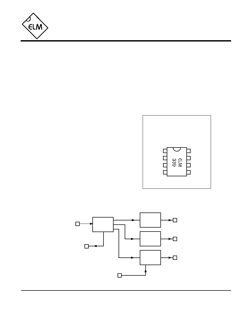
Connection Diagram
PDIP and SOIC
(top view)
V
DD
V
SS
1
2
3
4
8
7
6
5
Infrared Remote Control
The ELM339 is a complete remote control
decoder in an 8 pin package. With the addition of a
standard infrared receiver module, three individual
outputs can be simultaneously controlled using a
television remote control transmitter.
This circuit responds to SonyTM television control
codes, chosen because most universal remotes
default to them when initially powered up. The
ELM339 continuously monitors the stream of data
from an infrared receiver module looking for these
Sony type remote control codes. If an appropriate
three digit code is detected, the selected output
either turns on, turns off, or switches its state.
One of the outputs can be configured to provide
a 250msec pulse output, if desired. This could be
useful for interfacing to devices that expect a
momentary input, such as garage door controls,
alarm test buttons, and some appliances.
∑ Low power CMOS design - typically 1mA at 5V
∑ Three separate outputs
∑ Pulse output for momentary controls
∑ Signal received output for visual feedback
∑ Easy interface to standard receiver modules
∑ Works with universal TV remote transmitters
∑ High current drive outputs - up to 25 mA
∑ Basic home automation systems
∑ Remote smoke alarm test initiator
∑ Garage door controller
∑ Lamp controller
IRRx
LED
Out3
Out5
Description
Applications
Block Diagram
1 of 4
Features
ELM339DSA
Out7
Pulse7
2
3
4
6
7
Data
Decoder
5
Out7
Out5
Out3
Pulse7
Output
Driver
Output
Driver
Output
Driver
LED
IRRx

ELM339
Elm Electronics ≠ Circuits for the Hobbyist
< http://www.elmelectronics.com/ >
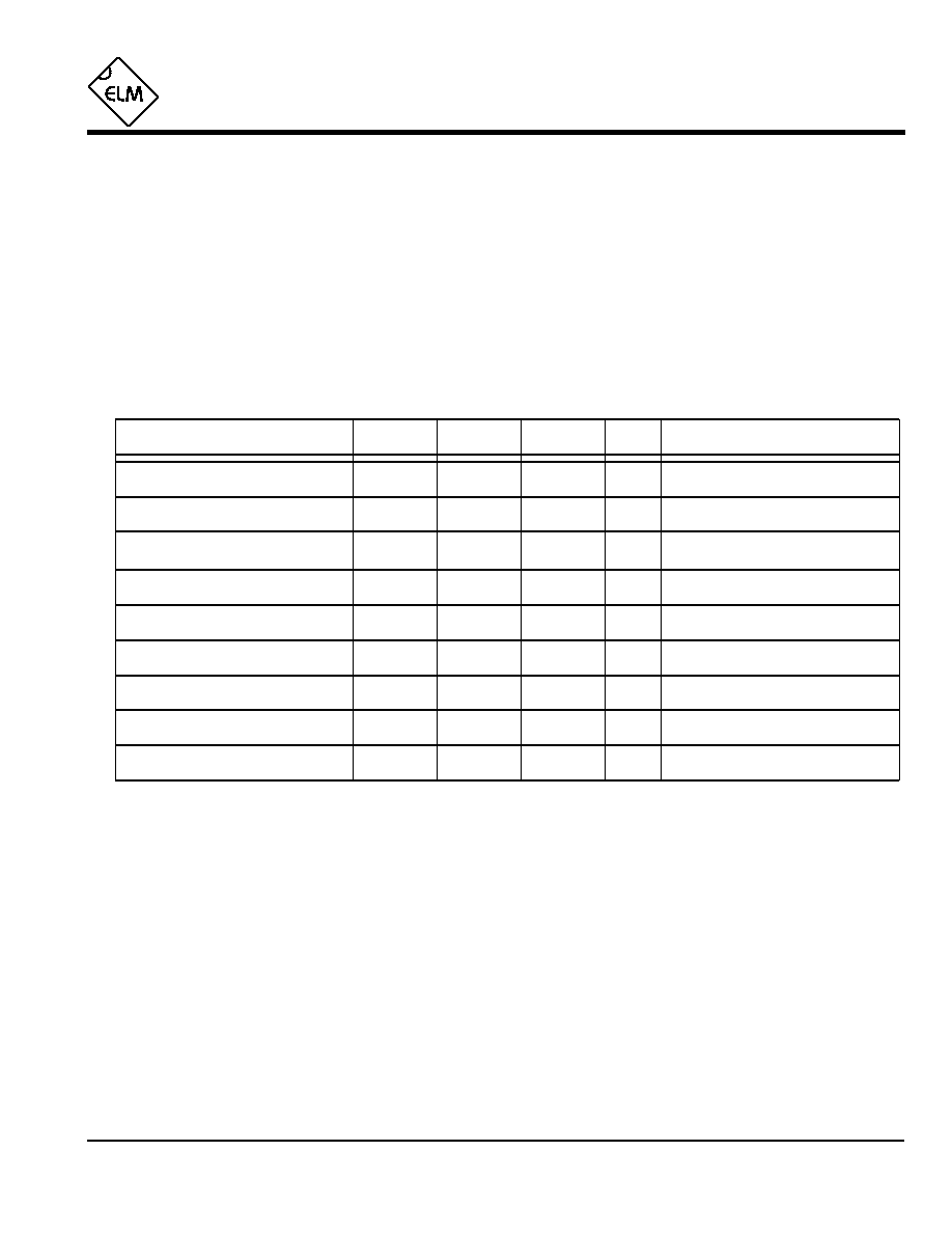
Pin Descriptions
Ordering Information
These integrated circuits are available in either the 300 mil plastic DIP format, or in the 200 mil SOIC surface
mount type of package. To order, add the appropriate suffix to the part number:
300 mil Plastic DIP............................... ELM339P
200 mil SOIC..................................... ELM339SM
2 of 4
All rights reserved. Copyright ©1998 Elm Electronics.
Every effort is made to verify the accuracy of information provided in this document, but no representation or warranty can be
given and no liability assumed by Elm Electronics with respect to the accuracy and/or use of any products or information
described in this document. Elm Electronics will not be responsible for any patent infringements arising from the use of these
products or information, and does not authorize or warrant the use of any Elm Electronics product in life support devices and/or
systems. Elm Electronics reserves the right to make changes to the device(s) described in this document in order to improve
reliability, function, or design.
V
DD
(pin 1)
This pin is the positive supply pin, and should
always be the most positive point in the circuit.
Internal circuitry connected to this pin is used to
provide power on reset of the microprocessor, so
an external reset signal is not required. Refer to
the Electrical Characteristics section for further
information.
Out5 (pin 2)
This output responds to all codes beginning with
the sequence 55. It can be forced to a high level
by issuing 551, to a low level with 550, and to
change state with the sequence 555. It powers up
to a logic low level.
Out7 (pin 3)
Out7 responds to all codes beginning with the
sequence 77. It can be forced to a high level by
issuing 771, to a low level with 770, and to
change state with the sequence 777, if the Pulse7
input is at a low level. If Pulse7 is at a high level,
a 250msec pulse will be output when any of the
three control codes are received.
Pulse7 (pin 4)
This input pin is used to modify the behavior of
Out7, as described above. A logic low level
applied to this pin results in unmodified behavior
of the output, while a logic high forces Out7 to the
pulse mode. Pulse width is nominally 250 msec.
IRRx (pin 5)
The output of a standard 40KHz infrared receiver
module is connected to this pin. The output of
such a module is normally at a high level, and
switches to a logic low when modulated carrier is
received. A series resistor of about 5K
must be
connected between this pin and the infrared
module output.
LED (pin 6)
This pin provides a logic high level output when a
valid code is being received by the ELM339. It is
suitable for driving an LED through a current
limiting resistor.
Out3 (pin 7)
This output responds to all codes beginning with
the sequence 33. It can be forced to a high level
by issuing 331, to a low level with 330, and to
change state with the sequence 333. It powers up
to a logic low level.
V
SS
(pin 8)
Circuit common is connected to this pin. This is
the most negative point in the circuit.
ELM339DSA
Elm Electronics ≠ Circuits for the Hobbyist
< http://www.elmelectronics.com/ >
ELM339
Electrical Characteristics
Absolute Maximum Ratings
Storage Temperature....................... -65∞C to +150∞C
Ambient Temperature with
Power Applied....................................-40∞C to +85∞C
Voltage on V
DD
with respect to V
SS
............ 0 to +7.5V
Voltage on any other pin with
respect to V
SS
........................... -0.6V to (V
DD
+ 0.6V)
Note:
Stresses beyond those listed here will likely damage
the device. These values are given as a design
guideline only. The ability to operate to these levels
is neither inferred nor recommended.
3 of 4
All values are for operation at 25∞C and a 5V supply, unless otherwise noted. For further information, refer to note 1 below.
Characteristic
Minimum
Typical
Maximum
Conditions
Units
Supply Voltage, V
DD
4.5
5.0
5.5
V
V
DD
rate of rise
0.05
V/ms
Average Supply Current, I
DD
1.0
2.4
mA
see note 3
Notes:
1. This integrated circuit is produced with a Microchip Technology Inc.'s PIC12C5XX as the core embedded
microcontroller. For further device specifications, and possibly clarification of those given, please refer to the
appropriate Microchip documentation.
2. This spec must be met in order to ensure that a correct power on reset occurs. It is quite easily achieved
using most common types of supplies, but may be violated if one uses a slowly varying supply voltage, as
may be obtained through direct connection to solar cells, or some charge pump circuits.
3. Device only. Does not include any LED or drive currents.
4. Pulse timing is affected by both temperature and supply voltage. Times shown are the widest variation that
can normally be expected.
5. The state of Pulse7 is determined after each valid 7 series code is sent. The level need not be set prior to
sending the codes.
Input low voltage
V
SS
0.15 V
DD
V
Input high voltage
V
DD
V
0.85 V
DD
Output low voltage
0.6
V
Output high voltage
V
V
DD
- 0.7
Current (sink) = 8.7mA
Current (source) = 5.4mA
see note 2
ELM339DSA
Out7 Pulse Width
260
msec
Pulse7 Setup Time
0
msec
see note 5
250
275
see note 4
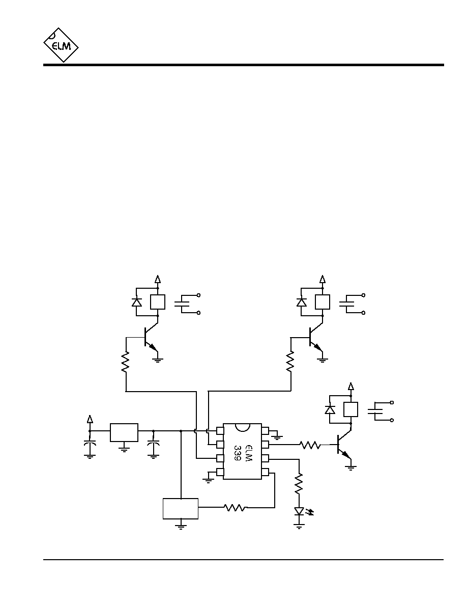
Example Application
4 of 4
Figure 1. Three Output Remote Control
Figure 1 shows a typical control circuit that uses the
ELM339. Relays are driven by each of the outputs,
providing isolation, and current carrying capability.
Transistor buffers are used to interface the circuit to the
12V relays.
All three of the outputs are used in the latching
mode, in this case. Converting Out7 (pin 3) to pulse
mode is easily accomplished by connecting pin 4 to 5V
rather than circuit common as shown. No other circuit
changes would be required.
Circuit operation is straight-forward. A serial data
stream is detected by the infrared module and passed
onto the ELM339 as a series of negative-going pulses.
The data is then decoded, and if found to contain the
correct SonyTM control code sequence, the state of the
selected output will be altered. The receiver modules
required are commonly available on the market, and are
manufactured by companies such as SharpTM or
LiteOnTM. A 40KHz module is required for a SonyTM
infrared remote, although 38KHz ones have been used
successfully.
In operation, ambient light can occasionally cause
an infrared receiver's bias level to drift towards V
SS
,
possibly tripping the ELM339's schmitt trigger input. As
the receiver output drifts high again, the Schmitt trigger
may not always reset, so that it might appear that there
is carrier present when it is not. This condition is
accounted for within the integrated circuit by
momentarily changing pin 5 to a high level output
before taking any measurements, thus reseting the
trigger. The series resistor must be used on pin 5 to
protect both circuits during this momentary high level
pulse. Typically a value of 4.7K
is sufficient.
Power supplies for this application are standard.
Regulated 5V is provided for the logic circuits, while
unregulated 12V is used for the relay coils.
ELM339
ELM339DSA
Elm Electronics ≠ Circuits for the Hobbyist
< http://www.elmelectronics.com/ >
560
4.7K
78L05
LED
+12V
0.1µF
1
2
3
4
8
7
6
5
+5V
0.1µF
2.2K
2N3904
1N4001
+12V
12V Relay
2N3904
1N4001
+12V
12V Relay
2.2K
2N3904
1N4001
Output "7"
+12V
12V Relay
Output "5"
Output "3"
40 KHz IR
Receiver
2.2K