 | –≠–ª–µ–∫—Ç—Ä–æ–Ω–Ω—ã–π –∫–æ–º–ø–æ–Ω–µ–Ω—Ç: ELM415P | –°–∫–∞—á–∞—Ç—å:  PDF PDF  ZIP ZIP |
ELM415
Elm Electronics ≠ Circuits for the Hobbyist
< http://www.elmelectronics.com/ >
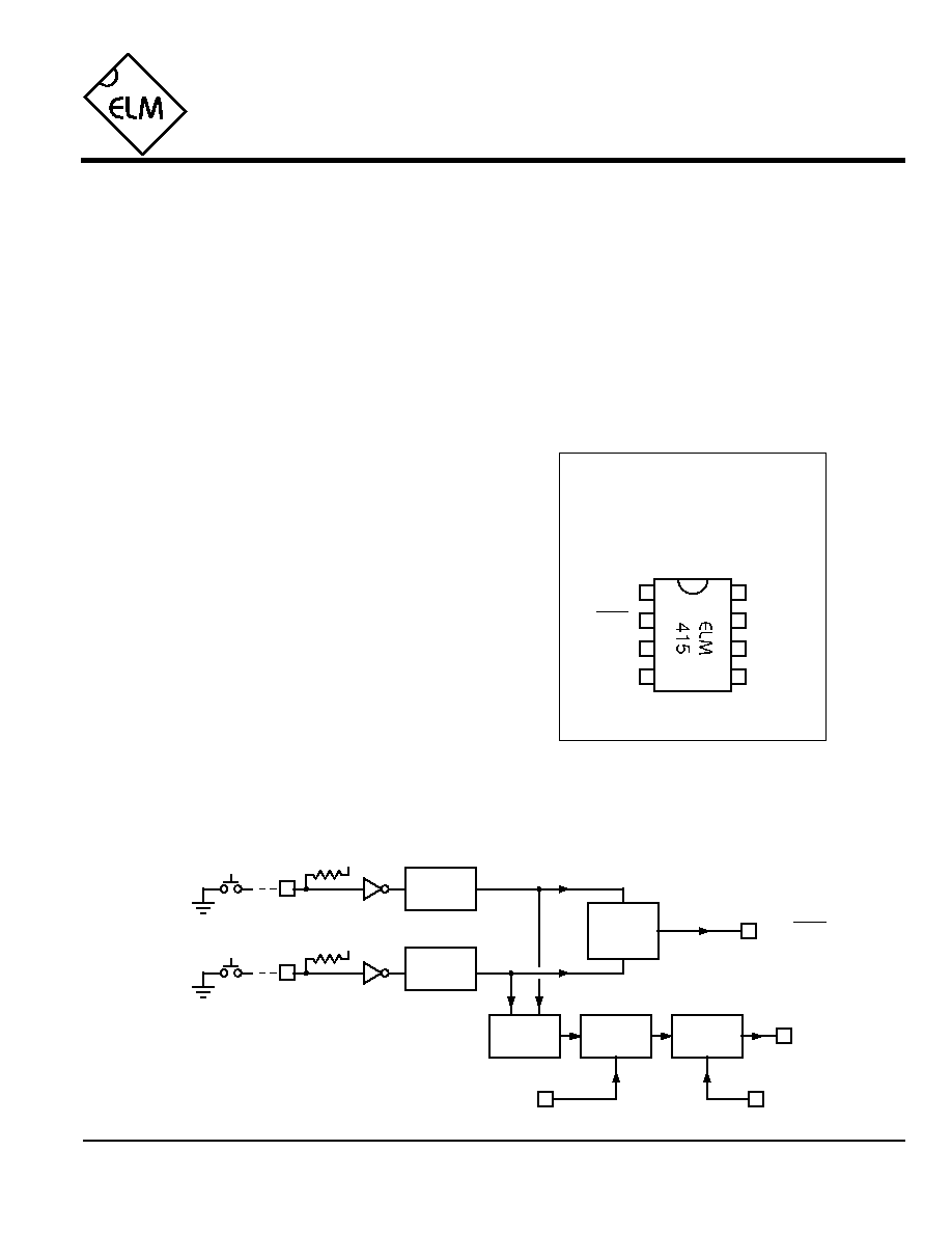
Connection Diagram
PDIP and SOIC
(top view)
V
DD
V
SS
1
2
3
4
8
7
6
5
Up/Down Interface
Many modern control circuits use the value from
a digital counter to directly determine a setting or
position. Manipulating this value under computer
control is not difficult, but when one has to interface
with a human operator, several other factors must be
considered. Human interfaces often require that the
circuit respond to changes in a setting ≠ up or down,
left or right, clockwise or counterclockwise. These
controls need a simple interface, which the ELM415
provides.
This 8 pin integrated circuit contains all the
timing and logic that is necessary to interface two
pushbuttons to most counter type interfaces. It reads
the position of the switches and translates that into
an appropriate signal for a counter to either
increment or decrement, which in turn controls the
output variable. Logic to filter out contact bounce, to
sense when both keys are pressed simultaneously,
to invert the count output, and to provide continuous
pulses if an input pushbutton stays pressed are all
included.
UpSw
Up/Down
Count
Description
∑ Digital audio potentiometer controls
∑ Variable voltage or temperature circuits
∑ Motor positioning controls
∑ Single-stepping control circuits
∑ Reset circuits
Applications
Block Diagram
1 of 5
∑ Low power CMOS design ≠ typically 1mA at 5V
∑ Wide supply range ≠ 3.0 to 5.5 volt operation
∑ Fully debounced switch inputs
∑ Internal pullup resistors provided
∑ Protection from simultaneous key presses
∑ High current drive outputs ≠ up to 25 mA
∑ User selectable automatic repeat function
∑ Selectable Count output polarity
Features
ELM415DSA
DownSw
Repeat
Invert
5
Count
Logic
4
Invert
UpSw
7
DownSw
Debounce
Circuit
2
Up/Down
6
3
Debounce
Circuit
V
DD
Latch
reset
set
Pulse
Generator
Output
Control
Repeat
V
DD

ELM415
Elm Electronics ≠ Circuits for the Hobbyist
< http://www.elmelectronics.com/ >
Pin Descriptions
Ordering Information
These integrated circuits are available in either the 300 mil plastic DIP format, or in the 200 mil SOIC surface
mount type of package. To order, add the appropriate suffix to the part number:
300 mil Plastic DIP............................... ELM415P
200 mil SOIC..................................... ELM415SM
2 of 5
All rights reserved. Copyright ©2002 Elm Electronics.
Every effort is made to verify the accuracy of information provided in this document, but no representation or warranty can be
given and no liability assumed by Elm Electronics with respect to the accuracy and/or use of any products or information
described in this document. Elm Electronics will not be responsible for any patent infringements arising from the use of these
products or information, and does not authorize or warrant the use of any Elm Electronics product in life support devices and/or
systems. Elm Electronics reserves the right to make changes to the device(s) described in this document in order to improve
reliability, function, or design.
V
DD
(pin 1)
This pin is the positive supply pin, and should always
be the most positive point in the circuit. Internal
circuitry connected to this pin is used to provide
power on reset of the microprocessor, so an external
reset signal is not required. Refer to the Electrical
Characteristics section for further information.
Up/Down (pin 2)
This is the count direction output, which changes
state depending on which pushbutton is being
pressed. If it is the Up pushbutton, this output will be
at a high level, while a Down results in it being at a
low level. The output remains at a level until the
alternate pushbutton is pressed. When it does
change, it does so approximately 1 msec prior to an
active pulse appearing on Count.
Count (pin 3)
This output provides a pulsing signal in response to
one of the two pushbuttons being pressed.
Simultaneous pressing of both switches is detected
and results in no output. The width of the output
pulse is fixed at approximately 1 msec, but the
polarity can be changed depending on the level at
the Invert input. This output is used to `clock' the
controlled counter circuit.
Invert (pin 4)
This input controls the quiescent level at pin 3 (the
Count output). If low, the level at pin 3 will also
normally be low, pulsing momentarily to a high level
when a button is pressed. Setting this pin high
causes pin 3 to rest at a high level, with the output
pulses momentarily going low.
Repeat (pin 5)
This input controls the circuit response should one of
the pushbuttons be continuously pressed. If this pin
is at a low level, there will only be a single Count
output generated, no matter how long the button
stays pressed. If this pin is at a high level, a single
pulse is output, then after a short delay, a continuous
stream of pulses are generated for as long as the
button is held.
UpSw (pin 6) and DownSw (pin 7)
The pushbuttons are connected to these pins.
Internal pullup resistors are provided to bias the
input when no button is pressed, simplifying the
circuitry required. These are standard CMOS inputs,
so the use of external delay components (capacitors,
etc.) is not recommended.
V
SS
(pin 8)
Circuit common is connected to this pin. This is the
most negative point in the circuit.
ELM415DSA
Elm Electronics ≠ Circuits for the Hobbyist
< http://www.elmelectronics.com/ >
ELM415
Electrical Characteristics
Absolute Maximum Ratings
Storage Temperature....................... -65∞C to +150∞C
Ambient Temperature with
Power Applied....................................-40∞C to +85∞C
Voltage on V
DD
with respect to V
SS
............ 0 to +7.5V
Voltage on any other pin with
respect to V
SS
........................... -0.6V to (V
DD
+ 0.6V)
Note:
Stresses beyond those listed here will likely damage
the device. These values are given as a design
guideline only. The ability to operate to these levels
is neither inferred nor recommended.
3 of 5
All values are for operation at 25∞C and a 5V supply, unless otherwise noted. For further information, refer to note 1 below.
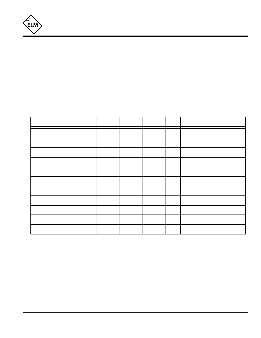
Characteristic
Minimum
Typical
Maximum
Conditions
Units
Supply voltage, V
DD
3.0
5.0
5.5
V
V
DD
rate of rise
0.05
V/ms
Average supply current, I
DD
1.0
2.4
mA
V
DD
= 5V, see note 3
Notes:
1. This integrated circuit is produced with a Microchip Technology Inc.'s PIC12C5XX as the core embedded
microcontroller. For further device specifications, and possibly clarification of those given, please refer to the
appropriate Microchip documentation.
2. This spec must be met in order to ensure that a correct power on reset occurs. It is quite easily achieved
using most common types of supplies, but may be violated if one uses a slowly varying supply voltage, as
may be obtained through direct connection to solar cells, or some charge pump circuits.
3. Pullup resistor currents are not included in this figure.
4. The value of the internal pullup resistance is both supply and temperature dependent.
5. The time for which the input must remain stable before it is considered valid by internal logic.
6. The Up/Down output will be stable for this time period before the output of a Count pulse.
Input low voltage
V
SS
0.15 V
DD
V
Input high voltage
V
DD
V
0.85 V
DD
Output low voltage
0.6
V
Output high voltage
V
V
DD
- 0.7
Current (sink) = 8.7mA
Current (source) = 5.4mA
Internal pullup resistance
see note 2
ELM415DSA
20
30
50
K
Pins 6 & 7, see note 4
Debounce period
msec
30
see note 5
Up/Down setup time
Count output pulse width
msec
1
msec
1
see note 6
Example Applications
4 of 5
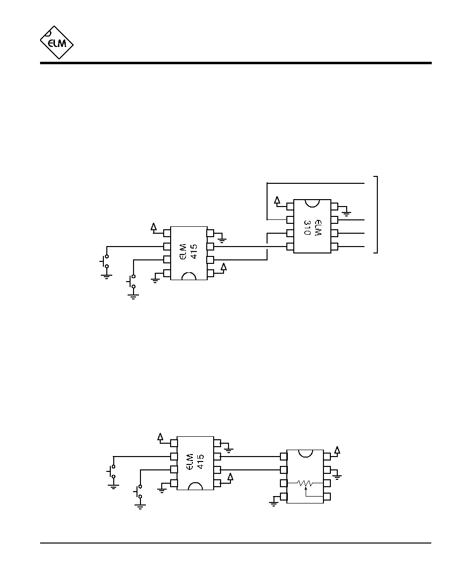
Figure 1. Controlling a stepper motor
Figure 1 shows the ELM415 used to interface two
pushbutton switches to an ELM310 stepper motor
controller, so that the motor position can be manually
controlled. For simplicity, the stepper motor and its
drive transistors are not shown in the diagram. Notice
that pin 5 has been tied to V
DD
in order to enable the
automatic repeat function, allowing the motor to move
`continuously' if a button is held down. Also, because
there are internal pullup resistors, the two pushbuttons
have been connected directly to the inputs without
further support circuitry.
Using the ELM310 to control a stepper motor has
many advantages ≠ low cost, low power, and ease of
use, for example. The disadvantage, however, is that
the integrated circuit is capable of responding very
quickly to input signals. This could result in multiple
steps of the motor, and perceived erratic motor
operation, if the input were not `debounced' by a circuit
such as the ELM415.
ELM415
ELM415DSA
Elm Electronics ≠ Circuits for the Hobbyist
< http://www.elmelectronics.com/ >
The circuit of Figure 2 is very similar to the one
above, but it uses an Analog Devices AD5220 Digital
Potentiometer as the controlled device. The up and
down buttons are used to `move' the wiper between
the two ends (pins 3 and 6). As shown, when stepped
in the Up direction, the AD5220 moves the wiper
towards the pin 3 end of the pot, while Down moves it
towards pin 6.
The AD5220 expects to have a Count signal that
is normally low, pulsing to a high level in order to
change the resistance, so pin 4 is connected to a low
(V
SS
) level, as shown. Some devices, such as the
Maxim MAX5160, require an inverted Count output,
which can be provided by simply tying pin 4 to V
DD
instead of V
SS
.
Figure 2. Controlling a digital potentiometer
2
3
4
7
6
5
V
DD
8
1
Down
Up
1
2
3
4
8
7
6
5
AD5220
V
DD
V
DD
2
3
4
7
6
5
1
2
3
4
8
7
6
5
+5V
8
1
A
B
C
D
To winding
drive circuits
Clockwise
+5V
Counter
clockwise
+5V

Example Applications (cont'd)
5 of 5
ELM415
ELM415DSA
Elm Electronics ≠ Circuits for the Hobbyist
< http://www.elmelectronics.com/ >
A variation of Figure 2 is shown in Figure 3. It uses
series resistors on the pushbutton inputs, and has also
had its autorepeat function modified slightly.
This circuit assumes that the pushbuttons are to
be mounted at a distance from the ELM415, which is
why the series resistors have been added. This is a
good practice to follow whenever working with CMOS
circuits that might be exposed to electrostatically
induced charges, as could be the case due to the extra
wiring for the switches. The resistors help to limit
induced currents which will flow through the IC's
internal protection diodes during a discharge, and in
doing so reduce the chance of latchup problems.
Generally, we recommend that protection resistors be
installed close to the IC whenever wiring is to extend
from the circuit by more than about twelve inches.
Figure 3. Controlling a digital potentiometer (with rapid down)
The other difference between the circuits of
Figures 2 and 3 is the connection between pins 5 and
6. This can best be explained by considering that in
Figure 3, due to the internal pullup resistor on pin 6,
pin 5 will normally be at V
DD
(enabling the repeat
function). When the Down button is pressed, the
autorepeat function will remain enabled, and multiple
pulses will be output. When the Up button is pressed,
however, it will pull both pins 5 and 6 low, disabling the
autorepeat and allowing only a single pulse to be
generated. This is useful if one wants the user to
explicitly press a button for each advance in one
direction, but will allow a rapid transition to a `safe'
position when the other button is pressed. This may be
a desireable feature if controlling the temperature in a
heater circuit, for example.
2
3
4
7
6
5
8
1
Down
Up
1
2
3
4
8
7
6
5
AD5220
V
DD
V
DD
1K
1K
Our final example shows how easily one can use
the ELM415 as a `one-shot' or monostable
multivibrator in a reset circuit. Often one has the need
to reset a circuit using a pushbutton, but multiple
2
3
4
7
6
5
8
1
Reset
V
DD
Reset
Output
Figure 4. Manual reset circuit
resets due to bouncing switches would be an
annoyance. Using the circuit of Figure 4, one can
generate a single clean reset pulse whenever the
pushbutton is pressed. If the circuit needs a negative-
going pulse, simply connect pin 4 to V
DD
rather than
V
SS
.
Hopefully this has provided you with several ideas
for using the ELM415 in your next project. Have you
considered using it to reset a timer whenever a contact
closes, or to count switch closures, or to determine an
object's direction based on the order in which the two
switches operated...