 | –≠–ª–µ–∫—Ç—Ä–æ–Ω–Ω—ã–π –∫–æ–º–ø–æ–Ω–µ–Ω—Ç: ELM446P | –°–∫–∞—á–∞—Ç—å:  PDF PDF  ZIP ZIP |
ELM446
Elm Electronics ≠ Circuits for the Hobbyist
< http://www.elmelectronics.com/ >
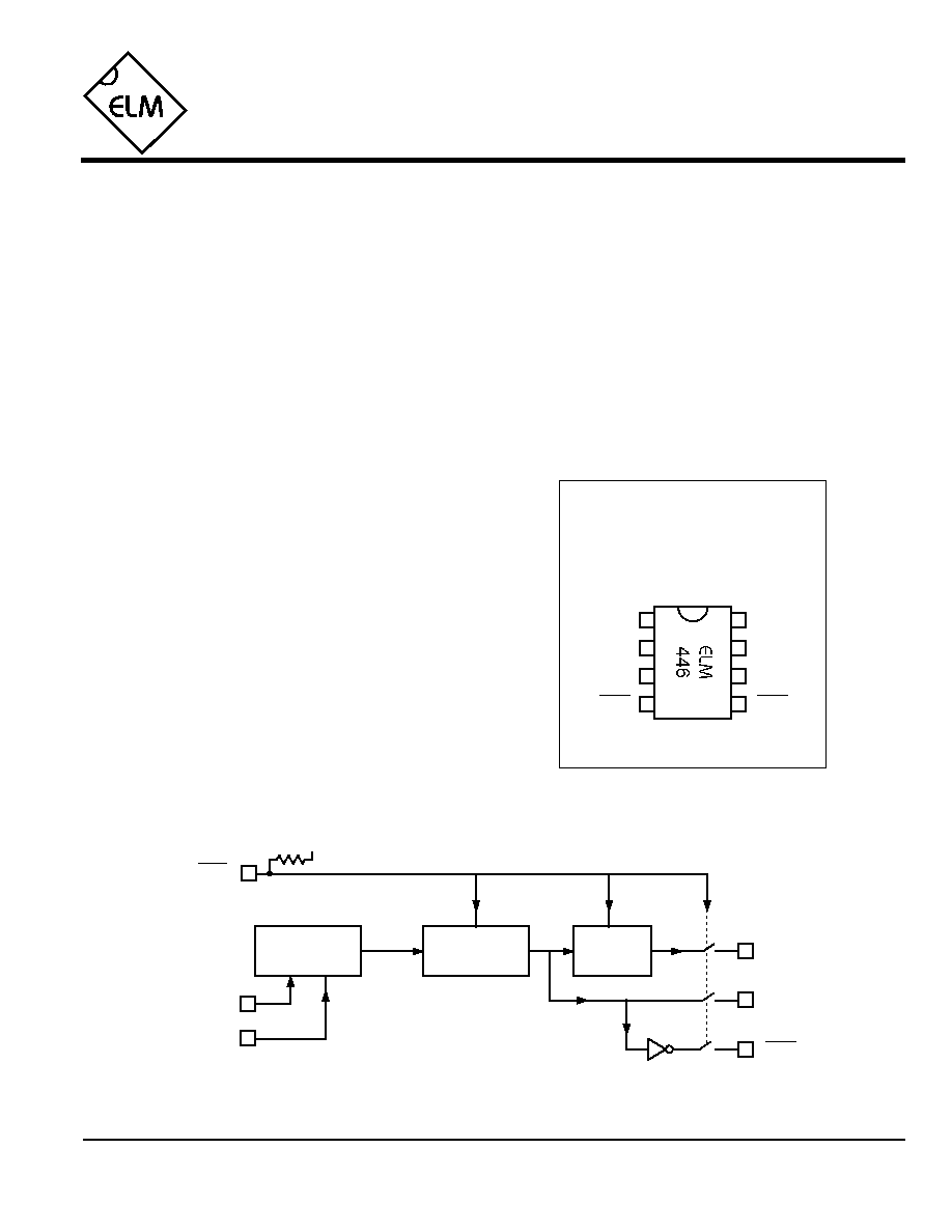
Connection Diagram
PDIP and SOIC
(top view)
V
DD
V
SS
1
2
3
4
8
7
6
5
50Hz Generator
The ELM446 is an 8 pin digital divider integrated
circuit, that provides both 50Hz and 1Hz outputs
from a common 3.58MHz NTSC colourburst crystal.
Externally, the designer need only provide the
crystal and two appropriate loading capacitors, as
well as a suitably bypassed power supply. Internal
oscillator circuits then use this reference frequency
to precisely derive a stable 50Hz signal. For
convenience, a complementary 50Hz signal is also
provided. This signal is then further divided to
provide a 1Hz signal output.
A reset input is provided to restart the internal
counters, if desired. An active low signal on this pin
will also force all of the outputs to an open or tristate
condition.
XT1
XT2
Description
∑ Stable 50Hz reference
∑ Master oscillator for clock / timekeeping functions
∑ Decimal based time reference for easier period
calculations
Applications
Block Diagram
1 of 3
∑ Low power CMOS design
∑ Wide supply range - 3.0 to 5.5 volt operation
∑ 3.58MHz crystal controlled operation
∑ Generates both 50Hz and 1Hz references
∑ Low parts count
∑ Complementary 50Hz outputs
∑ High current drive outputs - up to 25 mA
Features
ELM446DSB
1Hz
50Hz
reset
50Hz
2
3
XT1
XT2
5
50Hz
50Hz
Master
Oscillator
Divider
˜ 50
7
6
4
V
DD
reset
1Hz

ELM446
Elm Electronics ≠ Circuits for the Hobbyist
< http://www.elmelectronics.com/ >
Pin Descriptions
Ordering Information
These integrated circuits are available in either the 300 mil plastic DIP format, or in the 200 mil SOIC surface
mount type of package. To order, add the appropriate suffix to the part number:
300 mil Plastic DIP............................... ELM446P
200 mil SOIC..................................... ELM446SM
2 of 3
Absolute Maximum Ratings
Storage Temperature....................... -65∞C to +150∞C
Ambient Temperature with
Power Applied....................................-40∞C to +85∞C
Voltage on V
DD
with respect to V
SS
............ 0 to +7.5V
Voltage on any other pin with
respect to V
SS
........................... -0.6V to (V
DD
+ 0.6V)
Note:
Stresses beyond those listed here will likely damage
the device. These values are given as a design
guideline only. The ability to operate to these levels
is neither inferred nor recommended.
All rights reserved. Copyright ©1999 Elm Electronics.
Every effort is made to verify the accuracy of information provided in this document, but no representation or warranty can be
given and no liability assumed by Elm Electronics with respect to the accuracy and/or use of any products or information
described in this document. Elm Electronics will not be responsible for any patent infringements arising from the use of these
products or information, and does not authorize or warrant the use of any Elm Electronics product in life support devices and/or
systems. Elm Electronics reserves the right to make changes to the device(s) described in this document in order to improve
reliability, function, or design.
V
DD
(pin 1)
This pin is the positive supply pin, and should
always be the most positive point in the circuit.
Internal circuitry connected to this pin is used to
provide power on reset of the microprocessor, so
an external reset signal is not required. Refer to
the Electrical Characteristics section for further
information.
XT1 (pin 2) and XT2 (pin 3)
A 3.579545MHz NTSC television colourburst
crystal is connected between these two pins.
Crystal loading capacitors (typically 27pF) will
also normally be connected between each of the
pins and V
SS
.
reset (pin 4)
This pin can optionally be used to reset the
circuit by applying a logic low level to it. While
held low, all outputs are placed in an open or
tristate condition. If unused, this pin should be
left open (as a pullup resistor is provided) or
connected to V
DD
.
50Hz (pin 6) and 50Hz (pin 5)
These pins provide complementary 50Hz
outputs. Each has a nominal 50% duty cycle.
1Hz (pin 7)
The output on this pin is a 1Hz 50% duty cycle
signal.
V
SS
(pin 8)
Circuit common is connected to this pin. This is
the most negative point in the circuit.
ELM446DSB
Elm Electronics ≠ Circuits for the Hobbyist
< http://www.elmelectronics.com/ >
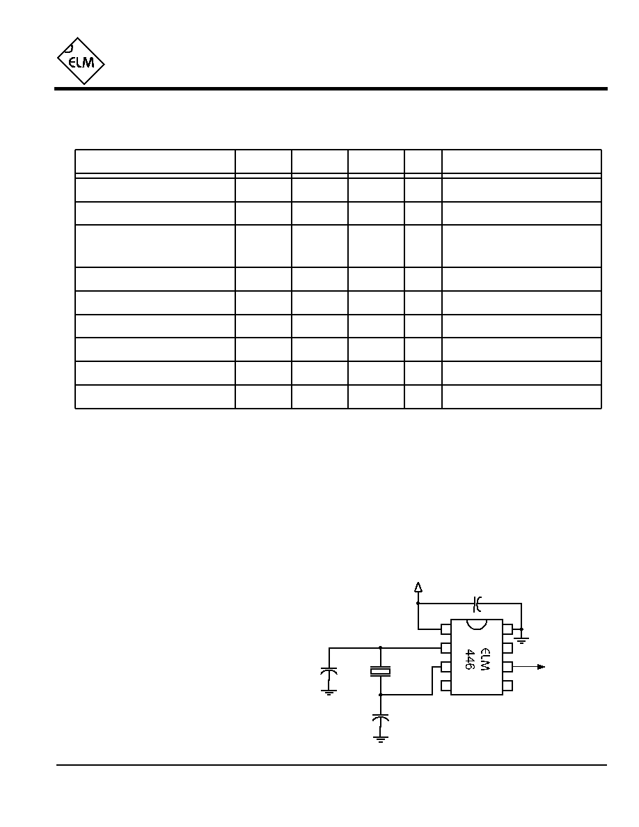
Example Application
ELM446
Electrical Characteristics
3 of 3
All values are for operation at 25∞C and a 5V supply, unless otherwise noted. For further information, refer to note 1 below.
Characteristic
Minimum
Typical
Maximum
Conditions
Units
Supply Voltage, V
DD
3.0
5.0
5.5
V
V
DD
rate of rise
0.05
V/ms
Average Supply Current, I
DD
0.60
2.4
mA
Notes:
1. This integrated circuit is produced with a Microchip Technology Inc.'s PIC12C5XX as the core embedded
microcontroller. For further device specifications, and possibly clarification of those given, please refer to the
appropriate Microchip documentation.
2. This spec must be met in order to ensure that a correct power on reset occurs. It is quite easily achieved
using most common types of supplies, but may be violated if one uses a slowly varying supply voltage, as
may be obtained through direct connection to solar cells, or some charge pump circuits.
3. The value of the pullup resistance is supply and temperature dependent.
Input low voltage
V
SS
0.15 V
DD
V
Input high voltage
V
DD
V
0.85 V
DD
Output low voltage
0.6
V
Output high voltage
V
V
DD
- 0.7
Current (sink) = 8.7mA
Current (source) = 5.4mA
see note 2
ELM446DSB
Output Duty Cycle
%
50
any output
0.1µF
+5V
1
2
3
4
8
7
6
5
50Hz Out
27pF
3.58MHz
Operation of the ELM446 is straightforward,
requiring little explanation. Typically it is
connected in a circuit as shown at the right.
Optionally, one might replace one of the fixed
value capacitors with a variable one, in order to
be able to trim the oscillator frequency for
greater accuracy. As usual, it is also good
practice to place a bypass capacitor across the
power supply as well.
0.35
2.4
mA
see note 3
Reset pin internal pullup resistance
V
DD
= 5V
V
DD
= 3V
K
470
300
600
27pF