 | –≠–ª–µ–∫—Ç—Ä–æ–Ω–Ω—ã–π –∫–æ–º–ø–æ–Ω–µ–Ω—Ç: ELM621 | –°–∫–∞—á–∞—Ç—å:  PDF PDF  ZIP ZIP |
ELM621
Elm Electronics ≠ Circuits for the Hobbyist
< http://www.elmelectronics.com/ >
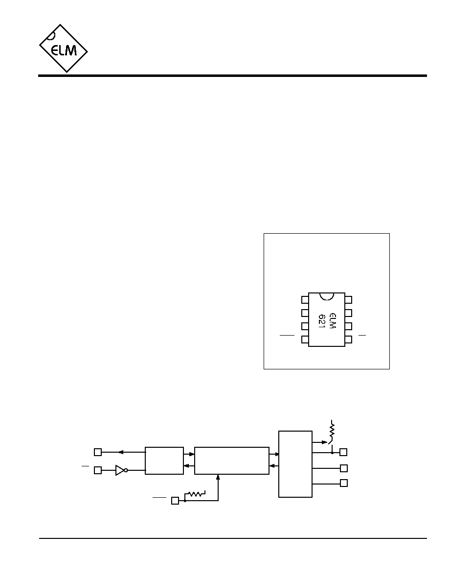
Connection Diagram
PDIP and SOIC
(top view)
V
DD
V
SS
Serial Three Bit Port
The ELM621 is a serially controlled, three bit
parallel I/O port in an 8 pin package. The high level
of integration employed means that very few
external components are required in order to
construct a fully functional circuit with this IC.
The ELM621 offers several convenient features
that many users will appreciate. The provision of a
16 byte buffer allows commands to be chained and
executed sequentially with one key stroke. The
controllable pullup resistor on the bit 3 port pin is
particularly helpful when interfacing to mechanical
switches, while the ability to control character echo
reduces overhead while operating under computer
control. Naturally, individual as well as simultaneous
read, set, clear and toggle commands are also
supported.
All communications with this device are via a
standard 9600 baud RS232 connection, using AT
style commands. No special characters are required,
so that virtually any terminal program can be used
with the ELM621. More advanced users will be
interested in operating this device under computer
program control ≠ simply a matter of writing to and
reading from the device.
∑ Low power CMOS design - typically 1mA
∑ High speed (9600 baud) RS232 communications
∑ Standard ASCII commands and responses
∑ 16 byte receive buffer
∑ Switchable pullup resistance
∑ Minimum of external components required
∑ External reset input
∑ High current drive outputs - up to 25 mA
∑ Home automation monitoring and control
∑ Robotics
∑ Security monitoring
∑ IC programmers
B3
Tx
Description
Applications
Block Diagram
1 of 6
Features
ELM621DSA
reset
Rx
1
2
3
8
7
6
5
4
B2
B1
Tx
RS232
Interface
Command
Interpreter
5
B1
B2
V
DD
reset
4
6
7
V
DD
Rx
B3
2
3
Port
Control

ELM621
Elm Electronics ≠ Circuits for the Hobbyist
< http://www.elmelectronics.com/ >
Pin Descriptions
Ordering Information
These integrated circuits are available in either the 300 mil plastic DIP format, or in the 200 mil SOIC surface
mount type of package. To order, add the appropriate suffix to the part number:
300 mil Plastic DIP............................... ELM621P
200 mil SOIC..................................... ELM621SM
2 of 6
All rights reserved. Copyright ©1999 Elm Electronics.
Every effort is made to verify the accuracy of information provided in this document, but no representation or warranty can be
given and no liability assumed by Elm Electronics with respect to the accuracy and/or use of any products or information
described in this document. Elm Electronics will not be responsible for any patent infringements arising from the use of these
products or information, and does not authorize or warrant the use of any Elm Electronics product in life support devices and/or
systems. Elm Electronics reserves the right to make changes to the device(s) described in this document in order to improve
reliability, function, or design.
V
DD
(pin 1)
This pin is the positive supply pin, and should
always be the most positive point in the circuit.
Internal circuitry connected to this pin is used to
provide power on reset of the microprocessor, so
an external reset signal is not required. Refer to
the Electrical Characteristics section for further
information.
B1 (pin 3), B2 (pin 2) and B3 (pin 7)
These are the three port pins that are software
configurable. At power-up, and after resetting,
these pins are inputs but can be individually set
as either input or output. The B3 pin has an
internal (nominally 30K
) pullup resistor that can
be enabled or disabled as required.
reset (pin 4)
This pin can be used to reset the circuit by
applying a momentary logic low level to it. If
unused, this pin should be left open (as a pullup
resistor is provided) or connected to V
DD
.
Rx (pin 5)
This is the RS232 receive input. Internal inversion
of the logic level allows the pin to be directly
connected to the DTE's TxD line through a single
current limiting resistor (typically about 47K
).
Precautions should be taken in the circuit design
to allow for the possibility that this input may be
left floating, due to a disconnected serial cable.
Typically, this only requires a large-valued
resistor between the RS232 TxD pin and Vss.
Tx (pin 6)
The RS232 data output pin. Signal level is
compatible with most inverting interface ICs, and
drive is sufficient to allow interfacing using only a
single PNP transistor. See the Example
Application section for more details.
V
SS
(pin 8)
Circuit common is connected to this pin. This is
the most negative point in the circuit.
ELM621DSA
Elm Electronics ≠ Circuits for the Hobbyist
< http://www.elmelectronics.com/ >
ELM621
Electrical Characteristics
Absolute Maximum Ratings
Storage Temperature....................... -65∞C to +150∞C
Ambient Temperature with
Power Applied....................................-40∞C to +85∞C
Voltage on V
DD
with respect to V
SS
............ 0 to +7.5V
Voltage on any other pin with
respect to V
SS
........................... -0.6V to (V
DD
+ 0.6V)
Note:
Stresses beyond those listed here will likely damage
the device. These values are given as a design
guideline only. The ability to operate to these levels
is neither inferred nor recommended.
3 of 6
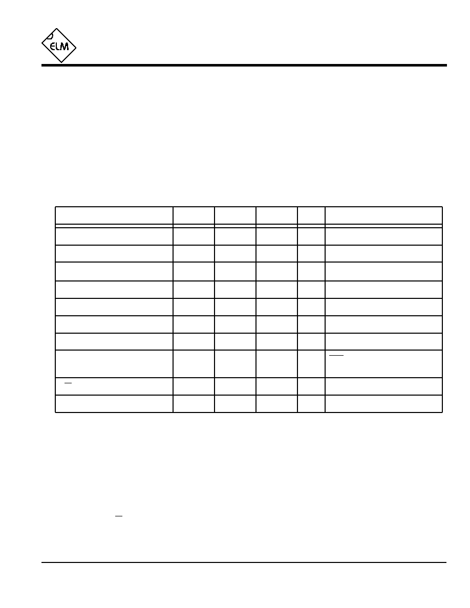
All values are for operation at 25∞C and a 5V supply, unless otherwise noted. For further information, refer to note 1 below.
Characteristic
Minimum
Typical
Maximum
Conditions
Units
Supply Voltage, V
DD
4.5
5.0
5.5
V
V
DD
rate of rise
0.05
V/ms
Average Supply Current, I
DD
1.0
2.4
mA
Notes:
1. This integrated circuit is produced with a Microchip Technology Inc.'s PIC12C5XX as the core embedded
microcontroller. For further device specifications, and possibly clarification of those given, please refer to the
appropriate Microchip documentation.
2. This spec must be met in order to ensure that a correct power on reset occurs. It is quite easily achieved
using most common types of supplies, but may be violated if one uses a slowly varying supply voltage, as
may be obtained through direct connection to solar cells, or some charge pump circuits.
3. The value of the internal pullup resistance is both supply and temperature dependent.
4. This specification represents the current flowing through the protection diodes when applying large voltages
to the Rx (pin 5) input through a current limiting resistance. Currents quoted are the maximum continuous.
5. The RS232 baud rate is derived from an internal oscillator that can typically vary by about ±3% over the full
temperature range with V
DD
= 5V. Data is transferred to and from the ELM621 with 8 data bits, no parity,
and 1 stop bit (8 N 1).
Logical low input voltage
V
SS
0.15 V
DD
V
V
DD
V
0.85 V
DD
Output low voltage
0.6
V
Output high voltage
V
V
DD
- 0.7
Current (sink) = 8.7mA
Current (source) = 5.4mA
see note 2
ELM621DSA
Internal pullup resistances
(see note 3)
500
K
300
600
reset (Pin 4)
Rx pin input current
mA
see note 4
-0.5
B3 (Pin 7) when enabled
K
30
20
50
RS232 Baud Rate
baud
see note 5
9600
+0.5
Logical high input voltage

The Command Line Interpreter
4 of 6
ELM621
ELM621DSA
Elm Electronics ≠ Circuits for the Hobbyist
< http://www.elmelectronics.com/ >
Design Considerations
The ELM621 makes it easy to quickly construct
a control circuit, but may be frustrating if you don't
keep a few things in mind. Here are some pointers to
consider...
When two power supplies are involved, always
try to have the ELM621 powered at either the same
time, or before applying power to the other circuitry.
Failing to do so may allow backfeed through the
(inherent) port pin protection diode, causing
unexplained and possibly erratic operation.
Keep in mind that this is a CMOS integrated
circuit, and that `latch-up' of the chip can thus occur.
To reduce the possibility, keep connecting cables as
short as possible, and consider placing a small value
resistor (100
to 220
) in series with the port pins.
The RS232 interface is not complicated, but
consideration must be given to the fact that the
receive signal is inverted from what would normally
be expected. This simplifies the RS232 interface
circuitry, but may result in some confusion. Refer to
the Example Application section for a typical method
of connection.
Under high-speed computer control, problems
may result due to the fact that there are no hand-
shaking signals provided. This is generally not a
problem if controlled by keyboard entry, as the
ELM621 is considerably faster than a human typist,
but under software control, one should always wait
for the prompt (`>') character before issuing another
command.
As a final note, it should be realized that linefeed
characters are not sent by the ELM621 with the
carriage returns. If viewing the output on a terminal,
many users may wish to have their terminal program
add the linefeeds in order to improve readability.
All commands are transmitted to the ELM621
one line at a time. A line consists of the character `A'
followed immediately by the letter `T', then up to 16
control characters, and a terminating carriage return
character (0x0D). The carriage return serves as an
execute command, the line not being translated and
executed until this character is received.
The 16 byte command buffer is implemented as
a `first-in first-out' (FIFO) type, retaining only the
most recent 16 characters since the last AT. Any
other characters are lost (there is no scroll-back
capability). The buffer is not cleared immediately
after executing a command line. This allows for a
`command line repeat' mode if a carriage return is
received immediately after executing a line. Receipt
of any other character will clear the buffer. This
feature is particularly useful when simply toggling a
bit on and off, or stringing two toggles together to
form a pulse in order to trigger another circuit.
A command line may contain spaces or commas
between the individual commands, as these do not
affect operation. Often when using a terminal, it is
convenient to separate commands with one of these
characters in order to improve readability, but keep
in mind that all two-character commands must not
have a comma or space between the two
characters.
One other feature of the interpreter is that it is
not case-sensitive. That is that it is able to accept
either upper or lower case characters in the input,
and they are treated equally (an `A' is treated the
same as `a', `T' is the same as `t', etc.)
Error reporting by the ELM621 is quite minimal.
Checking of a line for errors does not occur until
after the carriage return is received, and any error in
the input is reported with a simple question mark. If
there is any error detected in the syntax of a line,
none of the line is executed.
Occasionally there may be delays in the
transmission from the controlling device to the
ELM621, either due to the operator pausing, or to a
break in the communications channel. When a
pause of greater than 20 seconds occurs, the
ELM621 will time out and automatically return to its
`waiting for AT' state.

5 of 6
ELM621
ELM621DSA
Elm Electronics ≠ Circuits for the Hobbyist
< http://www.elmelectronics.com/ >
The following lists the commands that the
ELM621 recognizes. These are collectively referred
to as `AT' commands due to the fact that each line
must be preceeded by the letters `A' and `T'.
All commands except reset (`Z') require two
characters to be complete. The first is a descriptive
letter, while the second is chosen from one of the
options shown within the square brackets, adjacent
to the letter.
As an example, the R or read command can be
followed by either a 1, 2, 3, or an A, so to read the
state of bit 2, the command `AT R2' would be issued,
and AT RA will read all bits.
AT Commands
Device Control
E [ 1 | N ] - terminal echo on
Selecting either E1 or EN will cause all characters
sent to the ELM621 to be retransmitted (or echoed)
back to the controlling device.
E [ 0 | F ] - terminal echo off
Selecting either E0 or EF will stop the echoing of
characters back to the controlling device.
ID - show the device identification string
This command is used to display the type of device
connected and the ROM version.
Z - reset
This command is used to reset the ELM621 to the
power on state. All three port pins will be configured
as inputs, the pullup resistor will be off, the output
latches will be cleared, and terminal echo will be
on.
Port Control
I [ 1 | 2 | 3 | A ] - set port bit to input
Individually selects one, or simultaneously selects
all pins to be inputs, turning off the respective
output driver if it were on.
O [ 1 | 2 | 3 | A ] - set port bit to output
Selects one or all pins to be outputs, enabling the
respective output drivers. If the pullup were on, and
O3 or OA were issued, then the pullup would be
temporarily disabled. Returning B3 to the input
state would restore the pullup resistance.
P [ 1 | N ] - turn the B3 pullup resistance on
Selecting either P1 or PN will enable the internal
30K
resistor from pin 7 to V
DD
.
P [ 0 | F ] - turn the B3 pullup resistance off
Selecting either P0 or PF will disable the internal
30K
resistor from pin 7 to V
DD
.
Bit Control
C [ 1 | 2 | 3 | A ] - clear the output bit
Individually clears (to logic 0 or V
SS
) either one or all
of the port bits. If the pin(s) are also selected to be
outputs, then the logic level will appear immediately
on the output.
S [ 1 | 2 | 3 | A ] - set the output bit
Individually sets (to logic 1 or V
DD
) either one or all
of the port bits. If the pin(s) are also selected to be
outputs, then the logic level will appear immediately
on the output.
T [ 1 | 2 | 3 | A ] - toggle the state of the output bit
Reverses (or toggles) the logic level of the selected
pin(s). As with C or S, the pin(s) must also be
selected as outputs for an external change to occur.
The toggle command is convenient for creating
pulses, or strobes, on pins. For example, if bit 3 is
configured as an output, and is at a low level,
issuing the command AT T3 T3 will cause pin 7
(B3) to momentarily go to a high level, then return
low. As the ELM621 is interpreter driven, the width
of the pulse will be related to the number of
characters that need be translated. Minimum width
(~60µsec) is obtained with ATT3T3.
R [ 1 | 2 | 3 | A ] - read the level of the port pin
Reads the voltage level at the selected pin(s) and
reports the measured logic level. For example, if pin
2 is at V
DD
(logic 1), then issuing AT R2 will result
in a response of B2=1.