 | –≠–ª–µ–∫—Ç—Ä–æ–Ω–Ω—ã–π –∫–æ–º–ø–æ–Ω–µ–Ω—Ç: V6300 | –°–∫–∞—á–∞—Ç—å:  PDF PDF  ZIP ZIP |

R
V6300
V6301
Copyright © 2006, EM Microelectronic-Marin SA
1
www.emmicroelectronic.com
Ultra Low Power 3-Pin Power-On Reset IC
Description
The V6300 and V6301 are CMOS devices which monitor
the supply voltage of any electronic system, and generate
the appropriate Reset signal. The threshold defines the
minimum allowed voltage which guarantees the good
functionality of the system. As long as V
DD
stays upside this
voltage level, the output stays inactive. If V
DD
drops below
V
TH
, the output gets active. When V
DD
rises above V
TH
, the
output remains active for an additional 290 ms (V6301) or
50 ms (V6300). This allows the system to stabilize before
getting fully active. The threshold voltage may be obtained
in different versions: 2.0V, 2.4V, 2.8V, 3.5V, 4.0V, 4.5V.
Applications
All microprocessor applications where an automatic restart
is required:
Computer electronics
White / Brown goods
Automotive electronics
Industrial electronics
Telecom systems
Hand-held systems
Features
Clear microprocessor restart after power up
Processor reset at power down
Reset output guaranteed down to V
DD
= 1V
Low power consumption: typ. 3µA at V
DD
= 5V
-40 to +85∞C temperature range
Power-on reset time:
V6300: 50 ms (typ)
V6301: 290 ms (typ)
On-chip oscillator
No external components required
Push-pull or open drain active low Reset output
SOT-23 5L package
Typical Operating Configuration
V6300/01
Micro-
processor
V
DD
V
DD
V
SS
V
SS
RES
or
RES
RES
or
RES
V
DD
GND
For open drain version:
Fig. 1
Pin Assignment
V6300/01
2
3
1
5
4
V
SS
RES or
RES
V
DD
NC
NC
SOT23-5L
Fig. 2
EM MICROELECTRONIC -
MARIN SA

R
V6300
V6301
Copyright © 2006, EM Microelectronic-Marin SA
2
www.emmicroelectronic.com
Absolute Maximum Ratings
Parameter Symbol
Conditions
Voltage at V
DD
to V
SS
V
DD
-0.3V to +10V
Minimum voltage at RES or
RES
V
min
V
SS
≠ 0.3V
Maximum voltage at RES or
RES
V
max
V
DD
+ 0.3V
Storage Temperature Range
T
STO
-65∞C to +150∞C
Table 1
Stresses above these listed maximum ratings may cause
permanent damages to the device. Exposure beyond
specified operating conditions may affect device reliability or
cause malfunction.
Handling Procedures
This device has built-in protection against high static
voltages or electric fields; however, it is advised that normal
precautions be taken as for any other CMOS component.
Unless otherwise specified, proper operation can only occur
when all terminal voltages are kept within the voltage range.
Operating Conditions
Parameter Symbol
Min
Max
Unit
Operating Temperature
1)
T
A
-40
+125 ∞C
Positive Supply Voltage
V
DD
1 8 V
Table 2
1)
The maximum operating temperature is confirmed by
sampling at initial device qualification.
Electrical Characteristics
T
A
= -40 to +85∞C, unless otherwise specified
Parameter Symbol
Test
Conditions
Min.
Min @
25∞C
Typ.
Max. @
25∞C
Max. Unit
Supply current
1)
I
DD
V
DD
= 2V
3)
1.5
2.1
3.1
µA
I
DD
V
DD
= 5V
3.0
3.9
5.7
µA
I
DD
V
DD
= 8V
5.2
6.8
10.0
µA
Threshold voltage
V
TH
Version:
A,G,M
1.77 1.84 1.95 2.04 2.17 V
V
TH
Version:
B,H,N
2.09 2.18 2.32 2.41 2.55 V
V
TH
Version:
C,I,O
2.48 2.59 2.73 2.86 3.03 V
V
TH
Version:
D,J,P
3.11 3.23 3.42 3.59 3.80 V
V
TH
Version:
E,K,Q
3.55 3.70 3.88 4.08 4.32 V
V
TH
Version:
F,L,R
4.05 4.22 4.42 4.67 4.95 V
Threshold hysteresis
V
HYS
25
mV
RES Output Low Level
V
OL
V
DD
= 5V, I
OL
= 8mA
175
400
mV
V
OL
V
DD
= 3V, I
OL
= 4mA
140
300
mV
V
OL
V
DD
= 1V, I
OL
= 50µA
20
90
mV
RES Output High Level
V
OH
V
DD
= 5V, I
OH
= -8mA
4.3
4.5
V
V
OH
V
DD
= 3V, I
OH
= -4mA
2.3
2.6
V
V
OH
V
DD
= 1V, I
OH
=
-100µA
850 950
mV
Output leakage current
2)
I
LEAK
V
DD
= 8V
0.05
1
µA
Table 3
1)
RES
or
RES
open
2)
Only for Open drain versions
3)
Versions A, G and M are tested at V
DD
= 1.8V
Timing Characteristics
V
DD
= 5.0V, T
A
= -40 to +85∞C, unless otherwise specified
Parameter Symbol
Test
Conditions
Min.
Typ.
Max.
Units
Power on reset time:
V6300
V6301
t
POR
V6300
V6301
25
140
50
290
75
560
ms
ms
Sensitivity
4)
t
SEN
for
V
DD
= 5V to 3V in 5µs
20
0.8 t
R
µs
Reaction time
4)
t
R
for
V
DD
= 5V to 3V in 5µs
22 75 150
µs
Table 4
4)
Tested on versions with V
TH
higher than 3V

R
V6300
V6301
Copyright © 2006, EM Microelectronic-Marin SA
3
www.emmicroelectronic.com
Timing Waveforms
Fig. 3
Block Diagram
Fig. 4

R
V6300
V6301
Copyright © 2006, EM Microelectronic-Marin SA
4
www.emmicroelectronic.com
Pin Description
TO-92
Pin Name
Function
1 V
DD
Positive
supply
2
RES or RES
Reset output
3 V
SS
Supply
ground
Table 5
SOT23-5L
Pin Name
Function
1 NC
No
connection
2 V
SS
Supply
ground
3 NC
No
connection
4
RES or RES
Reset output
5 V
DD
Positive
supply
Table 6
Pin Assignment
TO-92
(ammopack)
V6300
2
3
1
5
4
V
SS
RES or
RES
V
DD
NC
NC
SOT23-5L
V
DD
V
SS
RES
or
RES
V6300
1
2
3
Fig.
7
Packaging and Ordering Information
Dimensions of SOT23-5L Package
Fig. 5
Dimensions of TO-92 Package (ammopack)
Dimensions in mm
Min Nom Max
A 4.32 4.95
D 4.45 4.95
F1/F2 2.44 2.54 2.94
H 18.00 18.00 20.00
H0 15.50 16.00 16.50
F1
F2
H
H
0
1
2
3
D
A
Fig. 6
R
V6300
V6301
Copyright © 2006, EM Microelectronic-Marin SA
5
www.emmicroelectronic.com
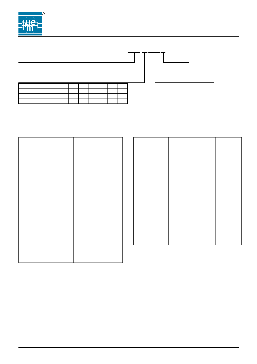
Ordering Information
Part Number:
V6300
SP5B +
Part Root
RoHS
V6300: t
POR
= 50 ms (typ)
+ = lead-free & green mold
V6301: t
POR
= 290 ms (typ)
[blank] = leaded
Threshold Voltage and Output Type
Package and Delivery Form
2.0V 2.4V 2.8V 3.5V 4.0V 4.5V
SP5B = SOT23-5, Tape & Reel, 3000 pcs
Push-pull, Reset active low
A
B
C
D
E
F
TO3E = TO92, Ammopack (not for new design)
Push-pull, Reset active high
G
H
I
J
K
L
Open drain, Reset active low
M
N
O
P
Q
R
Table 7
F
Subject to minimum order quantity and availability. Please contact EM Microelectronic for availability.
When ordering, please specify the complete Part Number without space between letters: eg. V6300FSP5B, V6301RSP5B, etc.
Package Marking for SOT23-5L
Part Number
Top
Marking
3)
Top Marking
1)
with 4
Characters
Top Marking
2)
with 3
Characters
V6300ASP5B ABAA BA#
V6300ASP5B+ E0## BBAA
V6300BSP5B ABAB BB#
V6300CSP5B PB## ABAC BC#
V6300CSP5B+ E7## BBAC
V6300DSP5B ABAD BD#
V6300ESP5B PA## ABAE BE#
V6300ESP5B+ E4## BBAE
V6300FSP5B P8## ABAF BF#
V6300FSP5B+ E2## BBAF
V6300GSP5B ABAG BG#
V6300HSP5B ABAH BH#
V6300ISP5B ABAI BI#
V6300JSP5B ABAJ BJ#
V6300KSP5B ABAK BK#
V6300LSP5B ABAL BL#
V6300LSP5B+ EM# BBAL
V6300MSP5B ABAM BM#
V6300NSP5B ABAN BN#
V6300OSP5B ABAO BO#
V6300OSP5B+ EE##
BBAL
V6300PSP5B ABAP BP#
V6300QSP5B ABAQ BQ#
V6300OSP5B ABAR BR#
V6300RSP5B+ EH## BBAR
Part Number
Top
Marking
3
Top Marking
1)
with 4
characters
Top Marking
2)
with 3
characters
V6301ASP5B ACAA
CA#
V6301ASP5B+ EN## BCAA
V6301BSP5B ACAB
CB#
V6301CSP5B ACAC
CC#
V6301DSP5B ACAD
CD#
V6301ESP5B ACAE
CE#
V6301FSP5B
ACAF
CF#
V6301FSP5B+ EP## BCAF
V6301GSP5B ACAG
CG#
V6301HSP5B ACAH
CH#
V6301ISP5B
ACAI
CI#
V6301JSP5B
ACAJ
CJ#
V6301KSP5B ACAK
CK#
V6301LSP5B
ACAL
CL#
V6301MSP5B ACAM
CM#
V6301NSP5B ACAN
CN#
V6301OSP5B ACAO
CO#
V6301OSP5B+ EL## BCAO
V6301PSP5B ACAP
CP#
V6301QSP5B ACAQ
CQ#
V6301RSP5B ACAR
CR#
Table
9
1)
Top marking with 4 characters is standard from 2003. For lead-free/green mold (RoHS) parts, the first letter of top marking
with 4 characters begins with letter "B" instead of letter "A". Bottom marking indicates the lot number.
2)
Top marking with 3 characters is kept as information since it was used until 2002.
Where # refers to the lot number (EM internal reference only)
3)
Top marking is the standard from 2006. No bottom marking exists. Where ## refers to the lot number (EM internal reference
only)
Traceability for small packages
Due to the limited space on the package surface, the bottom marking contains a limited number of characters that provide only
partial information for lot traceability. Full information for complete traceability is however provided on the packing labels of the
product at delivery from EM: It is highly recommended that the customer insures full lot traceability of EM product in his final
product.