
PhaseCap HD Capacitors for Power Factor Correction
MKK-Series
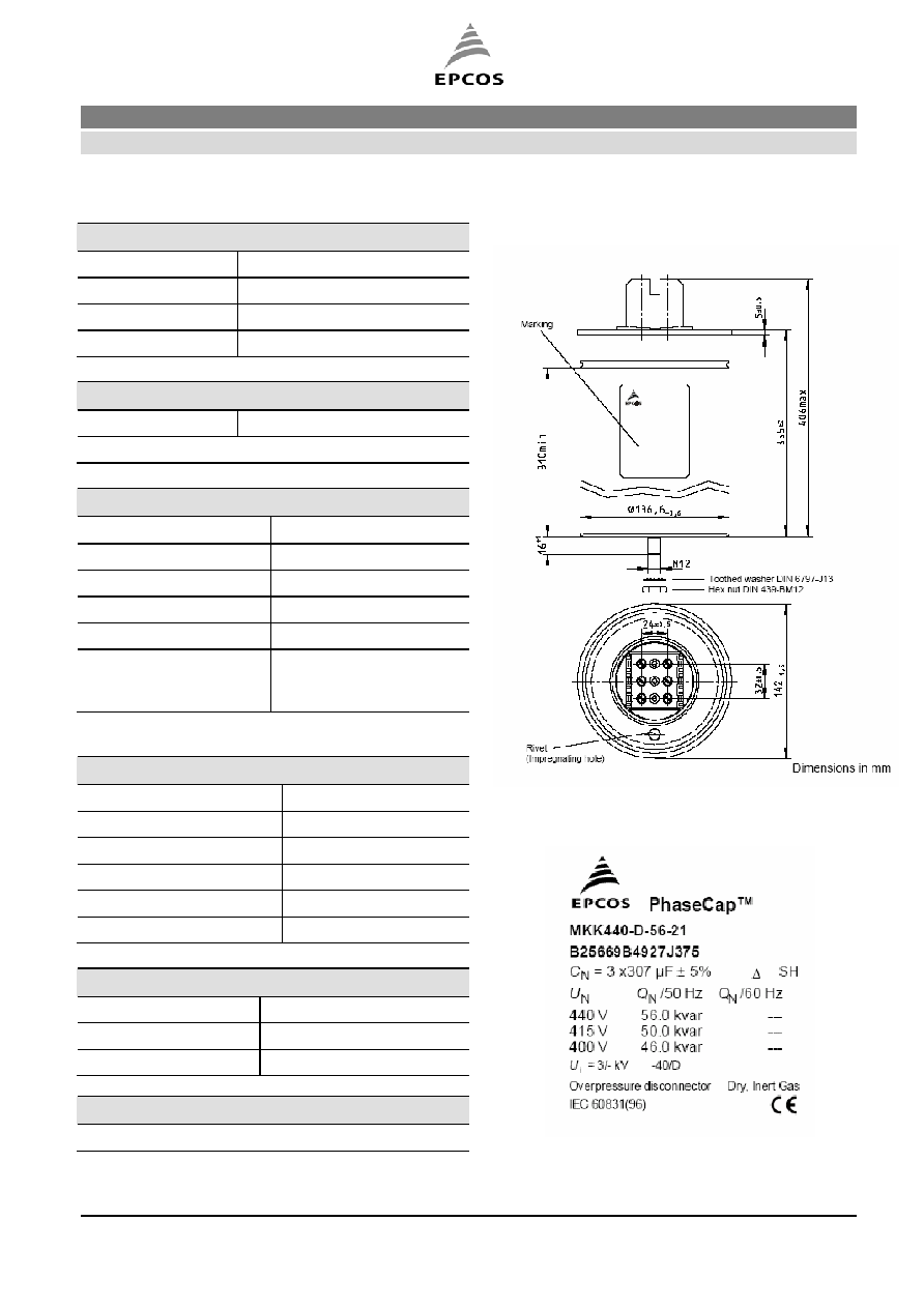
Series/Type: MKK440-D-56-21
Ordering code: B25669B4927J375
Date: 2005-12-14
Version: 3
Content of inside pages of data sheet. Data will be automatically entered into frontpage
headlines, headers and footers. Please fill in the table and then change the colour to "White".
This ensures that the table disappears for the customer PDF.
Identification/Classification 1:
(header 1)
PhaseCap HD Capacitors for Power Factor Correction
Identification/Classification 2:
(header 2)
MKK-Series
Ordering code:
B25669B4927J375
Series/Type: MKK440-D-56-21
Preliminary data (optional):
(if necessary)
Department:
FK PFC R&D
Date: 2005-12-03
© EPCOS AG 2005. Reproduction, publication and dissemination of this data sheet, enclosures hereto and the information
contained therein without EPCOS' prior express consent is prohibited.
PhaseCap HD Capacitors for Power Factor Correction
B25669B4927J375
MKK-Series
MKK440-D-56-21
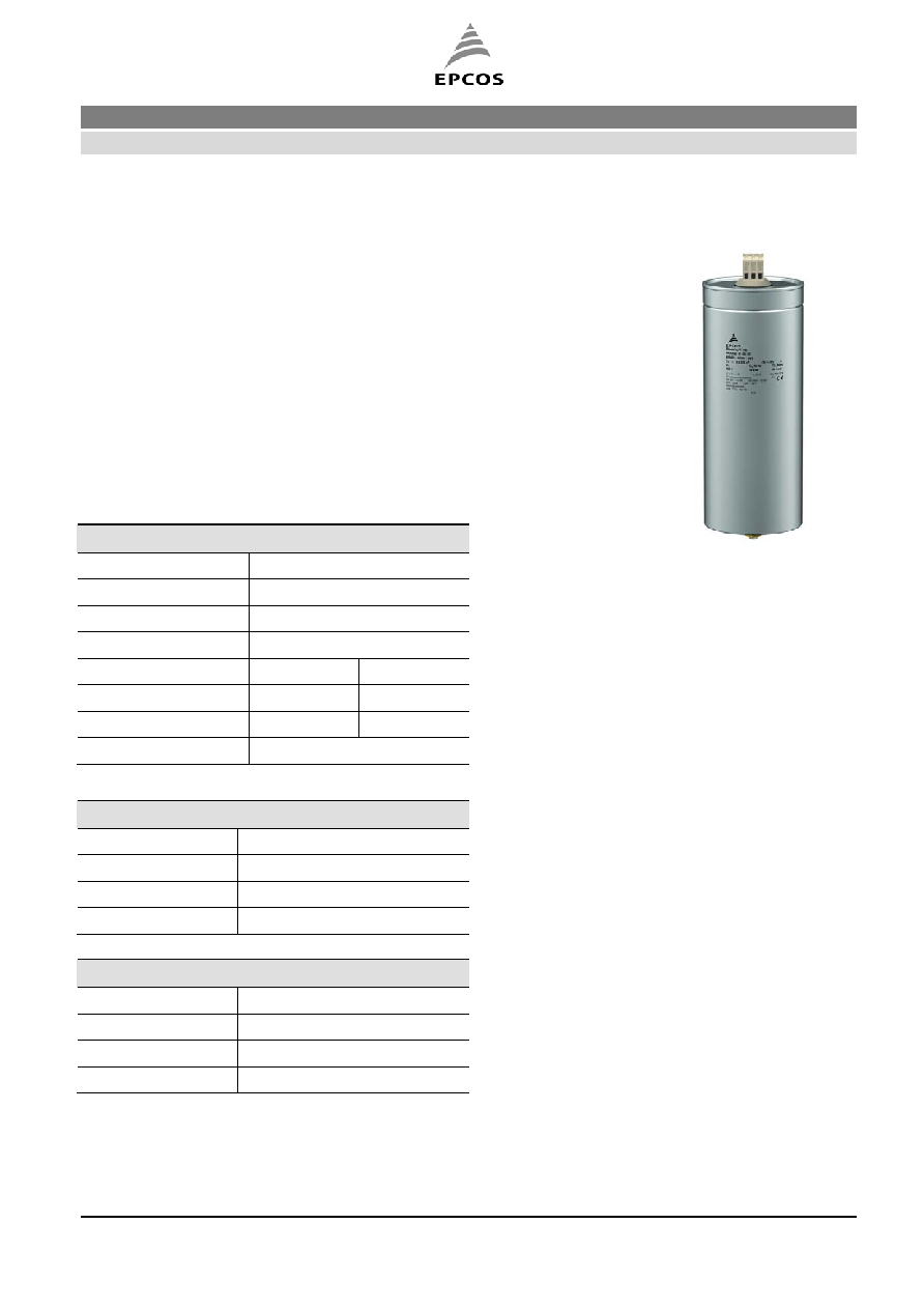
Construction
Dielectric: Polypropylene film
Gas-impregnated / dry type
Wave cut
Extruded round aluminum can with stud
Triple safety system
Features
Three phase, delta connected
Self-healing technology
Naturally air cooled (or forced air cooling)
Indoor mounting
Technical data and specifications
Characteristics
Rated capacitance C
R
3 x 307 µF
Tolerance
-5 / +10%
Connection D
(Delta)
Rated voltage V
R
440 VAC
Rated frequency
f
R
50 Hz
60 Hz
Output
56 kvar
----
Rated current I
R
74 A
----
tan (dielectric)
0.2 W / kvar
Maximum ratings
V
max
(up to 8 h daily) 480 VAC
V
max
(up to 1 min)
570 VAC
I
max
1.3 x I
R
(A)
I
S
200 x I
R
(A)
Test data
V
TT
950 VAC / 50 Hz during 10 s
V
TC
3000 VAC / 50 Hz during 10 s
tan (50 Hz)
0.45 W / kvar
FK PFC R&D
2005-12-03
Please read the important notes on page 7
Page 2 of 7
and the cautions and warnings.
PhaseCap HD Capacitors for Power Factor Correction
B25669B4927J375
MKK-Series
MKK440-D-56-21
Climatic category / -40/D
T
min
(-)
40 ∫C
T
max
(+)
55 ∫C
Humidity
av. rel. < 95%
Maximum altitude
4000 m
Mean life expectancy
t
LD
Up to 130000 hours
Max. 5000 switching per year acc. to IEC 60831
Design data
Dimensions (
x l)
142 x 355 mm
Weight approx
4.7 kg
Impregnation
Dry, inert gas
Fixing
Threaded bolt M12
Max. torque (Al can stud) 10 Nm
Mounting position
Upright. See "Maintenance
and Installation Manual"
for further details.
Terminals
Degree of protection
Isolated terminals IP20
Max. torque
2.5 Nm
Terminal cross section
35 mm
2
Maximum terminal current 100 A
Creepage distance
15 mm
Clearance
12 mm
Safety
Mechanical safety
Overpressure disconnector
Max. short circuit current (AFC: 10 kA)
Discharge resistor time 1 min (75 V)
Reference standards
IEC 60831-1/2. UL 810-5
th
edition
Dimensional drawing
Label design
FK PFC R&D
2005-12-03
Please read the important notes on page 7
Page 3 of 7
and the cautions and warnings.
PhaseCap HD Capacitors for Power Factor Correction
B25669B4927J375
MKK-Series
MKK440-D-56-21
Cautions and Warnings
In case of dents of more than 2 mm depth or any other mechanical damage, capacitors must not
be used at all.
To ensure the full functionality of the overpressure disconnector, elastic elements must not be
hindered and a minimum space of 5 cm has to be kept above each capacitor.
Do not handle the capacitor before it is discharged to max. 10% of rated voltage.
Resonance cases must be avoided by appropriate application design in any case.
Handle capacitors carefully, because they may still be charged even after disconnection due to
faulty discharging devices.
Protect the capacitor properly against over current and short circuit.
Failure to follow cautions may result, worst case, in premature failures, bursting and fire.
Discharging
Capacitors must be discharged to a maximum of 10% of rated voltage before they are switched in
again. This prevents an electric impulse discharge in the application, influences the capacitor's
service life and protects against electric shock. The capacitor must be discharged to 75 V or less
within 3 minutes. There must be not any switch, fuse or any other disconnecting device in the circuit
between the power capacitor and the discharging device. Discharge resistors are included in the
extend of delivery; alternatively discharge reactors are available from EPCOS. Discharge and short
circuit capacitor before handling!
Service life expectancy
Electrical components do not have an unlimited service life expectancy; this applies to self-healing
capacitors too. The maximum service life expectancy may vary depending on the application the
capacitor is used in.
Safety
Ensure good, effective grounding for capacitor enclosures.
Provide means of disconnecting and insulating a faulty component/bank.
Handle capacitors carefully, because they may still be charged even after disconnection due to
faulty discharging devices.
The terminals of capacitors, connected bus bars and cables as well as other devices may also be
energized.
Follow good engineering practice.
Overcurrent and short circuit protection
Use HRC fuses or MCCBs for short circuit protection. Short circuit protection and connecting
cables should be selected so that 1.5 times the rated capacitor current can be permanently
handled.
HRC fuses do not protect a capacitor against overload
- they are only for short circuit protection.
The HRC fuse rating should be 1.6 to 1.8 times rated capacitor current.
Do not use HRC fuses to switch capacitors (risk of arcing).
Use thermal magnetic overcurrent relays for overload protection.
FK PFC R&D
2005-12-03
Please read the important notes on page 7
Page 4 of 7
and the cautions and warnings.
PhaseCap HD Capacitors for Power Factor Correction
B25669B4927J375
MKK-Series
MKK440-D-56-21
Resonance cases
Resonance cases must be avoided by appropriate application design in any case. Maximum total
RMS capacitor current (incl. fundamental harmonic current) specified in technical data must not be
exceeded.
Overtemperature
Exceeding maximum allowed temperature may set the safety device out of operation.
Overpressure Disconnector
To ensure full functionality of an overpressure disconnector, the following must be observed:
1. The elastic elements must not be hindered, i.e.
- connecting lines must be flexible leads (cables),
- there must be sufficient space (min. 5 cm) for expansion above the connections (see
"Clearing distance for overpressure disconnector").
- folding beads must not be retained by clamps.
2. Maximum allowed fault current of 10000 A in accordance with UL 810 standard must be assured by
the application.
3. Stress parameters of the capacitor must be within the IEC60831 specification.
Re-switching vs. phase-opposition
In case of voltage interruption, a sufficient discharge time has to be ensured to avoid phase-
opposition and resulting high inrush currents
.
Vibration resistance
The resistance to vibration of capacitors corresponds to IEC 68, part 2≠6.
Max. test conditions:
Test duration
2 h
Frequency range 1
0 ... 55 Hz corresponding
to max. 0.7 g
Displacement amplitude
0.75 mm
These figures apply to the capacitor alone. Because the fixing and the terminals may influence the
vibration properties, it is necessary to check stability when a capacitor is built in and exposed to
vibration. Irrespective of this, you are advised not to locate capacitors where vibration amplitude
reaches the maximum in strongly vibrating equipment.
Mechanical protection
The capacitor has to be installed in a way that mechanical damages and dents in the aluminum can
are avoided.
FK PFC R&D
2005-12-03
Please read the important notes on page 7
Page 5 of 7
and the cautions and warnings.