
Film Capacitors
Metallized Polyester Film Capacitors (MKT)
Series/Type:
B32572, B32573
Date:
August 2004
© EPCOS AG 2004. Reproduction, publication and dissemination of this data sheet, enclosures hereto and the
information contained therein without EPCOS' prior express consent is prohibited.
Purchase orders are subject to the General Conditions for the Supply of Products and Services of the Electrical
and Electronics Industry recommended by the ZVEI (German Electrical and Electronic Manufacturers' Associ-
ation), unless otherwise agreed.
Typical applications
Ignition for
gas, engines, generators
Energy storage
Climatic
Max. operating temperature: 125
∞
C
Climatic category (IEC 60068-1): 55/125/56
Features
Special dimensions available on request
High pulse strength
Construction
Dielectric: polyethylene terephthalate
(polyester, PET)
Stacked-film technology
Uncoated
Terminals
Parallel wire leads, lead-free tinned
Marking
Rated capacitance (coded),
rated DC voltage
Delivery mode
Bulk (untaped)
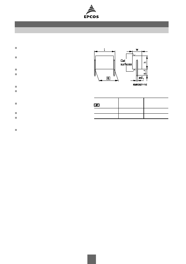
Dimensional drawing
Dimensions in mm
Lead spacing
±
0.4
Lead diameter
d
1
Type
15.0
0.8
B32572
22.5
0.8
B32573
Notes on mounting
When mounting these capacitors, take into account creepage distances and clearances to
adjacent live parts. The insulating strength of the cut surfaces to other live parts of the circuit is
1.5 times the capacitors rated DC voltage, but is always at least 300 VDC.
Metallized polyester film capacitors (MKT)
B32572, B32573
Ignition (stacked) SilverCap
TM
2

Overview of available types
Lead spacing 15.0 mm
22.5 mm
Type
B32572
B32573
Page
4
5
V
R
(VDC)
250
250
V
rms
(VAC)
160
160
C
R
(
µ
F)
0.68
1.0
1.5
2.2
B32572, B32573
Ignition (stacked) SilverCap
TM
3
Ordering codes and packing units (lead spacing 15 mm)
V
R
VDC
V
rms
f
60 Hz
VAC
C
R
µ
F
Max. dimensions
w
◊
h
◊
l
mm
Ordering code
(composition see
below)
Untaped
pcs./unit
Further E series and intermediate capacitance values on request.
Special dimensions available on request.
For
corresponding
design
rules,
refer
to
chapter
"General
technical
infor
mation".
Composition of ordering code
+ =
Capacitance tolerance code:
M =
±
20%
K =
±
10%
J =
±
5%
250
160
0.68
7.0
◊
11.0
◊
16.5
B32572A3684+000
450
1.0
9.1
◊
11.7
◊
16.5
B32572A3105+000
300
1.5
11.5
◊
13.5
◊
16.5
B32572A3155+000
200
2.2
11.5
◊
19.8
◊
16.5
B32572A3225+000
150
B32572
Ignition (stacked) SilverCap
TM
4
Ordering codes and packing units (lead spacing 22.5 mm)
V
R
VDC
V
rms
f
60 Hz
VAC
C
R
µ
F
Max. dimensions
w
◊
h
◊
l
mm
Ordering code
(composition see
below)
Untaped
pcs./unit
Further E series and intermediate capacitance values on request.
Special dimensions available on request.
For
corresponding
design
rules,
refer
to
chapter
"General
technical
infor
mation".
Composition of ordering code
+ =
Capacitance tolerance code:
M =
±
20%
K =
±
10%
J =
±
5%
250
160
0.68
5.6
◊
9.2
◊
24.0
B32573A3684+000
1180
1.0
6.4
◊
11.8
◊
24.0
B32573A3105+000
1050
1.5
7.6
◊
14.3
◊
24.0
B32573A3155+000
930
2.2
8.9
◊
17.4
◊
24.0
B32573A3225+000
560
B32573
Ignition (stacked) SilverCap
TM
5
1) Test criteria must be met after exposure to damp heat for 21 days
Technical data
Operating temperature range
Max. operating temperature T
op,max
+125
∞
C
Upper category temperature T
max
+125
∞
C
Lower category temperature T
min
55
∞
C
Rated temperature T
R
+85
∞
C
Dissipation factor tan
(in 10
-3
) at
C
R
1
µ
F
C
R
> 1
µ
F
at 20
∞
C
1 kHz
8
10
(upper limit values)
10 kHz
15
Time constant
= C
R
R
ins
2500 s
at 20
∞
C, rel. humidity
65%
(minimum as-delivered values)
DC test voltage
1.6
V
R
, 2 s
Category voltage V
C
T
A
(
∞
C)
DC voltage derating
AC voltage derating
(continuous operation with V
DC
T
A
85
V
C
= V
R
V
C,rms
= V
rms
or V
AC
at f
60 Hz)
85<T
A
125
V
C
= V
R
(165 T
A
)/80
V
C,rms
=V
rms
(165 T
A
)/80
Max. charging voltage C
ch
1.2
V
R
for
1 s
Damp heat test
56 days
1)
/40
∞
C/93% relative humidity
Limit values after damp
Capacitance change
C/C
5%
heat test
Dissipation factor change
tan
3
10
-3
(at 1 kHz)
5
10
-3
(at 10 kHz)
Time constant
= C
R
R
ins
50% of minimum
as-delivered values
Reliability:
Failure rate
2 fit (
2
10
-9
/h) at 0.5
V
R
, 40
∞
C
Service life t
SL
200 000 h at 1.0
V
R
, 40
∞
C
For conversion to other operating conditions and temperatures,
refer to chapter "Quality assurance", page .
Failure criteria:
Total failure
Short circuit or open circuit
Failure due to variation
Capacitance change
C/C
> 10%
of parameters
Dissipation factor tan
> 2
upper limit value
Time constant
= C
R
R
ins
< 50 s
B32572, B32573
Ignition (stacked) SilverCap
TM
6
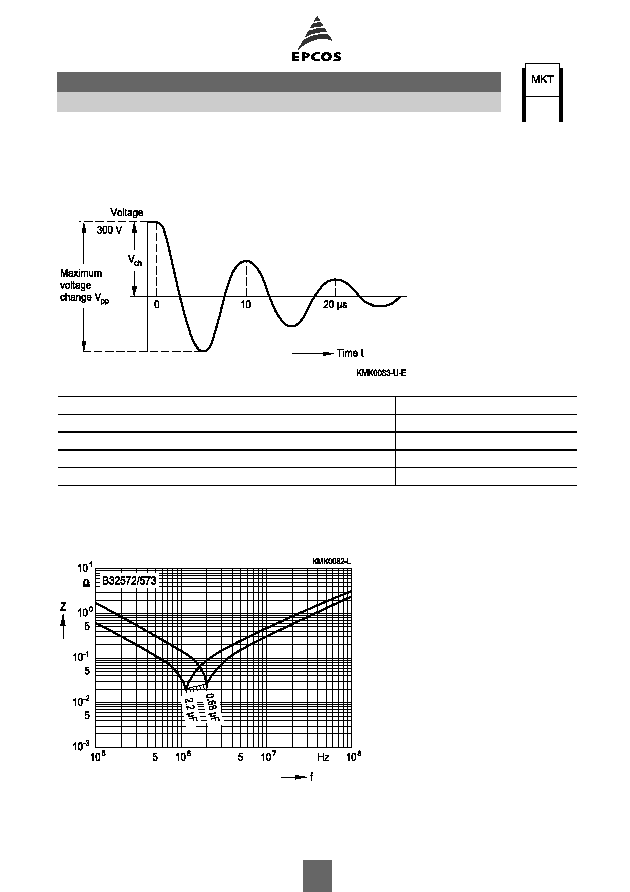
Pulse handling capability
The capacitors are especially manufactured and tested to suit their intended applications.
Typical permissible loads:
Lead spacing
15 and 22.5 mm
Max. rate of voltage rise V
pp
/
(at V
pp
= 500 V)
200 V/
µ
s
Pulse characteristic k
0
(at V
pp
500 V)
200 000 V
2
/
µ
s
Max. charging voltage V
ch
(
1 s)
300 VDC
Max. voltage change V
pp
( at f = 100 kHz)
500 V
Unlimited number of pulses permitted.
Impedance Z versus frequency f
(typical values)
B32572, B32573
Ignition (stacked) SilverCap
TM
7

Permissible AC voltage V
rms
versus frequency f (for sinusoidal waveforms, T
A
55
∞
C)
For T
A
>55
∞
C, please refer to "General technical information", section 3.2.3.
Lead spacing 15 mm
250 VDV/160 VAC
Lead spacing 22.5 mm
250 VDC/160 VAC
B32572, B32573
Ignition (stacked) SilverCap
TM
8