
Film Capacitors
Metallized Polypropylene Film Capacitors (MKP)
Series/Type:
B32612 ... B32614
Date:
August 2004
© EPCOS AG 2004. Reproduction, publication and dissemination of this data sheet, enclosures hereto and the
information contained therein without EPCOS' prior express consent is prohibited.
Purchase orders are subject to the General Conditions for the Supply of Products and Services of the Electrical
and Electronics Industry recommended by the ZVEI (German Electrical and Electronic Manufacturers' Associ-
ation), unless otherwise agreed.

Typical applications
TV (S-correction, flyback)
Electronic ballasts
Climatic
Max. operating temperature: 110
∞
C
Climatic category (IEC 60068-1): 55/100/56
Construction
Dielectric: polypropylene (PP)
Wound capacitor technology
Epoxy resin coating (UL 94 V-0)
Features
Very high pulse strength
Terminals
Crimped wire leads, lead-free tinned,
lead length (6
1 mm) or min. 20 mm
Double crimped wire leads, lead-free tinned
Straight wire leads, lead-free tinned,
lead length (17
±
3) mm
Different lead spacings (reduced and enlarged) available,
lead length (6
1 mm)
Marking
Manufacturer's logo, style and type (P61x),
rated capacitance (coded),
capacitance tolerance (code letter),
rated DC voltage, date of manufacture (code)
Delivery mode
Bulk (untaped)
Taped (Ammo pack or reel)
For notes on taping, refer to chapter "Taping and packing".
Metallized polypropylene film capacitors (MKP)
B32612 ... B32614
Pulse application (wound)
2
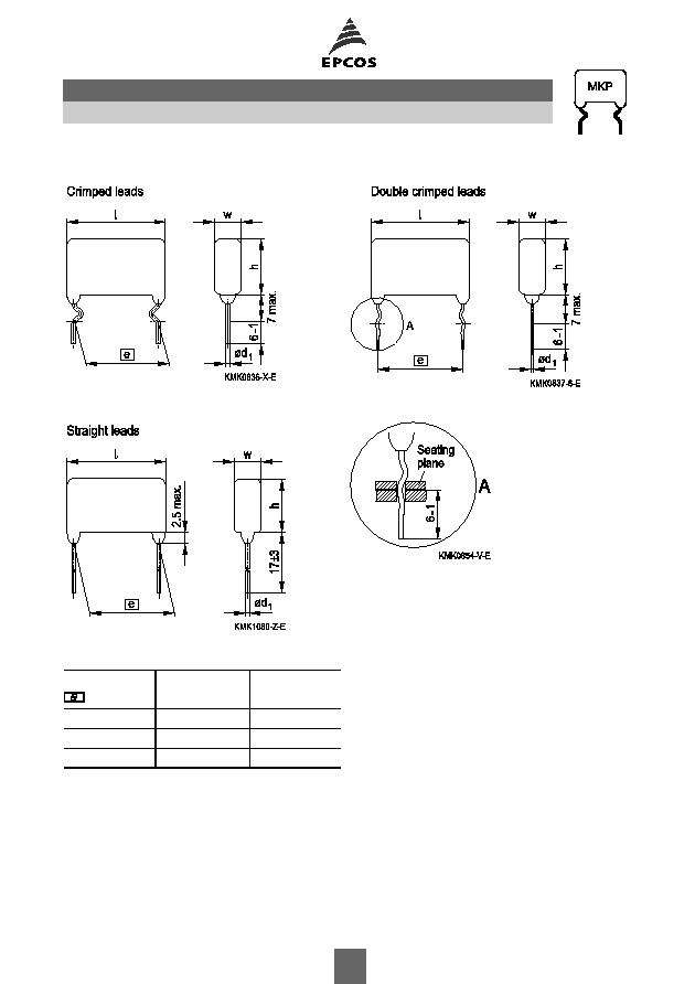
Dimensional drawings
Detail of double crimped version
Dimensions in mm
Lead spacing
±
0.8
Lead diameter
d
1
Type
15.0
0.8
B32612
22.5
0.8
B32613
27.5
0.8
B32614
B32612 ... B32614
Pulse application (wound)
3
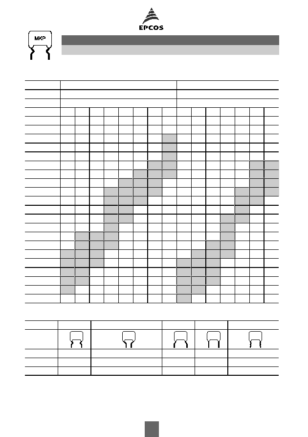
Overview of available types
Lead spacing 15.0 mm
22.5 mm
Type
B32612
B32613
Page
6
8
V
R
(VDC)
250 400 630 1000 1250 1600 1600 2000 250 400 630 1000 1600 2000 2000
V
rms
(VAC)
160 200 250 250 500 500 700 700 160 200 250 250 500 700 1000
C
R
(nF)
1.0
1.5
2.2
3.3
4.7
6.8
10
15
22
33
47
68
100
150
220
330
470
680
1000
Lead configurations
Serie
Standard
Reduced
Enlarged
Straight
Double crimped
B32612
15 mm
7.5 / 10 / 12.5 mm
17.5 mm
15 mm
15 mm
B32613
22.5 mm
15 / 17.5 / 20 mm
25 mm
22.5 mm
22.5 mm
B32614
27.5 mm
25 mm
27.5 mm
27.5 mm
B32612 ... B32614
Pulse application (wound)
4
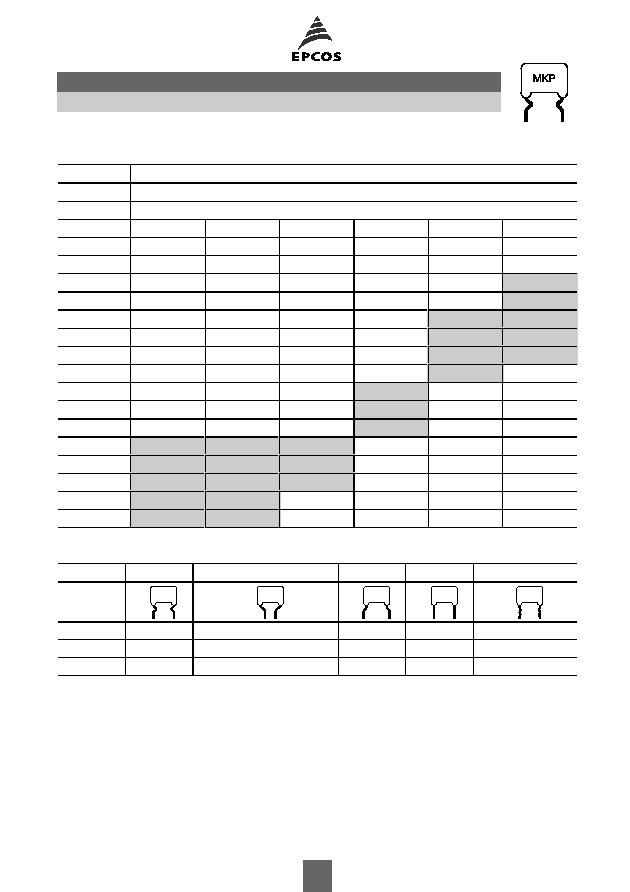
Overview of available types
Lead spacing 27.5 mm
Type
B32614
Page
10
V
R
(VDC)
250
400
630
1000
1600
2000
V
rms
(VAC)
160
200
250
250
500
700
C
R
(nF)
10
15
22
33
47
68
100
150
220
470
680
1000
1500
2200
Lead configurations
Serie
Standard
Reduced
Enlarged
Straight
Double crimped
B32612
15 mm
7.5 / 10 / 12.5 mm
17.5 mm
15 mm
15 mm
B32613
22.5 mm
15 / 17.5 / 20 mm
25 mm
22.5 mm
22.5 mm
B32614
27.5 mm
25 mm
27.5 mm
27.5 mm
B32612 ... B32614
Pulse application (wound)
5
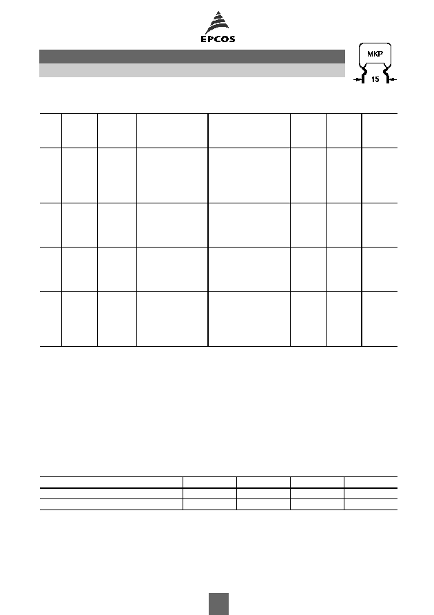
Ordering codes and packing units (lead spacing 15 mm)
V
R
VDC
V
rms
f
1 kHz
VAC
C
R
nF
Max. dimensions
w
◊
h
◊
l
mm
Ordering code
(composition see
below)
Ammo
pack
pcs./unit
Reel
pcs./unit
Untaped
pcs./unit
Further E series and intermediate capacitance values on request.
Composition of ordering code
+ =
Capacitance tolerance code:
*** = Packaging code:
K =
±
10%
J =
±
5%
289 = Ammo pack
189 = Reel
010 = Untaped crimped (lead length 6
1 mm)
011 = Untaped crimped (lead length min. 20 mm)
008 = Untaped (straight, lead length 17
±
3 mm)
020 = Double crimped (lead length 6
1 mm)
Packaging codes for further lead configurations (untaped):
Lead configuration (lead length 6
1 mm)
Reduced
Reduced
Reduced
Enlarged
Lead spacing (mm)
7.5 mm
10 mm
12.5 mm
17.5 mm
Packaging code
030
040
050
060
250 160
150
6.5
◊
12.5
◊
18.0 B32612A3154+***
850
1100
1000
220
7.0
◊
13.5
◊
18.0 B32612A3224+***
800
1000
1000
330
8.0
◊
14.5
◊
18.0 B32612A3334+***
700
900
500
470
9.5
◊
16.0
◊
18.0 B32612A3474+***
600
800
500
680
11.5
◊
17.5
◊
18.0 B32612A3684+***
500
650
500
400 200
68
6.5
◊
12.0
◊
18.0 B32612A4683+***
850
1100
1000
100
7.0
◊
12.5
◊
18.0 B32612A4104+***
800
1000
1000
150
7.5
◊
12.5
◊
18.0 B32612A4154+***
750
1000
1000
220
8.0
◊
14.5
◊
18.0 B32612A4224+***
700
900
500
330
9.5
◊
16.0
◊
18.0 B32612A4334+***
600
800
500
470
11.0
◊
17.5
◊
18.0 B32612A4474+***
500
650
500
630 250
68
6.5
◊
12.0
◊
18.0 B32612A6683+***
850
1100
1000
100
7.5
◊
13.0
◊
18.0 B32612A6104+***
750
1000
1000
150
9.0
◊
14.5
◊
18.0 B32612A6154+***
600
800
500
220
10.0
◊
16.5
◊
18.0 B32612A6224+***
550
750
500
1000 250
10
7.0
◊
12.5
◊
18.0 B32612A0103+***
800
1000
1000
15
8.0
◊
13.5
◊
18.0 B32612A0153+***
700
900
1000
22
9.0
◊
15.5
◊
18.0 B32612A0223+***
600
800
1000
33
6.5
◊
13.0
◊
18.0 B32612A0333+***
850
1100
1000
47
7.0
◊
15.5
◊
18.0 B32612A0473+***
800
1000
1000
68
8.5
◊
16.5
◊
18.0 B32612A0683+***
650
850
500
100
11.0
◊
17.5
◊
18.0 B32612A0104+***
500
650
500
B32612
Pulse application (wound)
6
Ordering codes and packing units (lead spacing 15 mm)
V
R
VDC
V
rms
f
1 kHz
VAC
C
R
nF
Max. dimensions
w
◊
h
◊
l
mm
Ordering code
(composition see
below)
Ammo
pack
pcs./unit
Reel
pcs./unit
Untaped
pcs./unit
Further E series and intermediate capacitance values on request.
Composition of ordering code
+ =
Capacitance tolerance code:
*** = Packaging code:
K =
±
10%
J =
±
5%
289 = Ammo pack
189 = Reel
010 = Untaped crimped (lead length 6
1 mm)
011 = Untaped crimped (lead length min. 20 mm)
008 = Untaped (straight, lead length 17
±
3 mm)
020 = Double crimped (lead length 6
1 mm)
Packaging codes for further lead configurations (untaped):
Lead configuration (lead length 6
1 mm)
Reduced
Reduced
Reduced
Enlarged
Lead spacing (mm)
7.5 mm
10 mm
12.5 mm
17.5 mm
Packaging code
030
040
050
060
1250 500
6.8
7.0
◊
11.0
◊
18.0 B32612A7682+***
800
1000
1000
10
7.5
◊
13.0
◊
18.0 B32612A7103+***
750
1000
1000
15
8.0
◊
14.0
◊
18.0 B32612A7153+***
700
900
500
22
9.5
◊
15.5
◊
18.0 B32612A7223+***
600
800
500
33
11.0
◊
17.5
◊
18.0 B32612A7333+***
500
650
500
1600 500
4.7
6.5
◊
12.0
◊
18.0 B32612A1472+***
850
1100
1000
6.8
8.0
◊
13.0
◊
18.0 B32612A1682+***
700
900
500
10
9.0
◊
14.5
◊
18.0 B32612A1103+***
600
800
500
15
10.0
◊
17.5
◊
18.0 B32612A1153+***
550
750
500
1600 700
3.3
6.5
◊
11.5
◊
18.0 B32612J1332+***
850
1100
1000
4.7
7.5
◊
12.5
◊
18.0 B32612J1472+***
750
1000
1000
6.8
8.5
◊
14.5
◊
18.0 B32612J1682+***
650
850
500
10
9.5
◊
17.0
◊
18.0 B32612J1103+***
600
800
250
2000 700
1.0
7.0
◊
10.5
◊
18.0 B32612A2102+***
800
1000
1000
1.5
7.5
◊
11.5
◊
18.0 B32612A2152+***
750
1000
1000
2.2
8.0
◊
14.5
◊
18.0 B32612A2222+***
700
900
1000
3.3
8.5
◊
15.0
◊
18.0 B32612A2332+***
650
850
500
4.7
9.5
◊
18.0
◊
18.0 B32612A2472+***
600
800
500
B32612
Pulse application (wound)
7
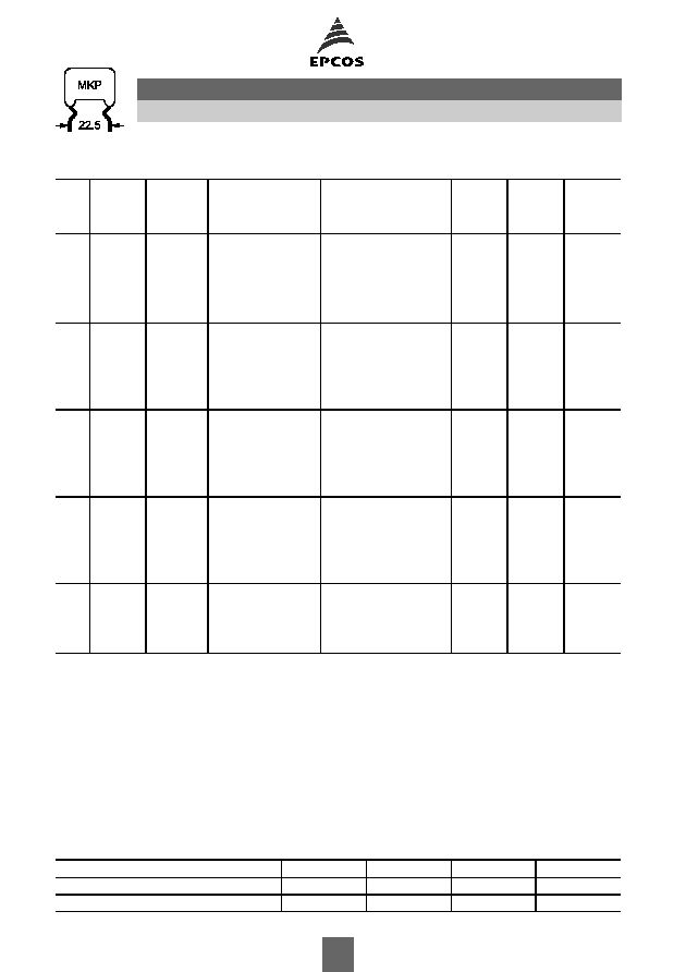
Ordering codes and packing units (lead spacing 22.5 mm)
V
R
VDC
V
rms
f
1 kHz
VAC
C
R
nF
Max. dimensions
w
◊
h
◊
l
mm
Ordering code
(composition see
below)
Ammo
pack
pcs./unit
Reel
pcs./unit
Untaped
pcs./unit
Further E series and intermediate capacitance values on request.
Composition of ordering code
+ =
Capacitance tolerance code:
*** = Packaging code:
K =
±
10%
J =
±
5%
289 = Ammo pack
189 = Reel
010 = Untaped crimped (lead length 6
1 mm)
011 = Untaped crimped (lead length min. 20 mm)
008 = Untaped (straight, lead length 17
±
3 mm)
020 = Double crimped (lead length 6
1 mm)
Packaging codes for further lead configurations (untaped):
Lead configuration (lead length 6
1 mm)
Reduced
Reduced
Reduced
Enlarged
Lead spacing (mm)
15 mm
17.5 mm
20 mm
25 mm
Packaging code
055
060
030
080
250
160
220
7.0
◊
14.5
◊
26.5 B32613A3224+***
500
700
500
330
7.0
◊
14.5
◊
26.5 B32613A3334+***
500
700
500
470
8.0
◊
15.5
◊
26.5 B32613A3474+***
450
600
500
680
9.5
◊
16.0
◊
26.5 B32613A3684+***
350
500
500
1000
11.0
◊
19.0
◊
26.5 B32613A3105+***
300
450
250
400
200
150
7.0
◊
13.5
◊
26.5 B32613A4154+***
500
700
500
220
7.0
◊
14.0
◊
26.5 B32613A4224+***
500
700
500
330
8.0
◊
16.0
◊
26.5 B32613A4334+***
450
600
500
470
9.5
◊
16.0
◊
26.5 B32613A4474+***
350
500
250
680
11.5
◊
17.5
◊
26.5 B32613A4684+***
300
400
250
630
250
100
7.0
◊
12.5
◊
26.5 B32613A6104+***
500
700
250
150
7.5
◊
14.0
◊
26.5 B32613A6154+***
450
650
250
220
9.0
◊
15.5
◊
26.5 B32613A6224+***
400
550
250
330
10.0
◊
18.0
◊
26.5 B32613A6334+***
350
500
250
470
11.0
◊
20.0
◊
26.5 B32613A6474+***
300
450
250
1000
250
33
8.5
◊
14.5
◊
26.5 B32613A0333+***
400
550
500
47
10.0
◊
15.5
◊
26.5 B32613A0473+***
350
500
250
68
11.0
◊
17.5
◊
26.5 B32613A0683+***
300
450
250
100
10.0
◊
16.5
◊
26.5 B32613A0104+***
350
500
250
150
12.0
◊
18.0
◊
26.5 B32613A0154+***
300
400
250
1600
500
10
7.0
◊
13.5
◊
26.5 B32613A1103+***
500
700
500
15
8.0
◊
14.5
◊
26.5 B32613A1153+***
450
600
500
22
9.0
◊
17.0
◊
26.5 B32613A1223+***
400
550
250
33
10.5
◊
18.5
◊
26.5 B32613A1333+***
350
450
250
B32613
Pulse application (wound)
8
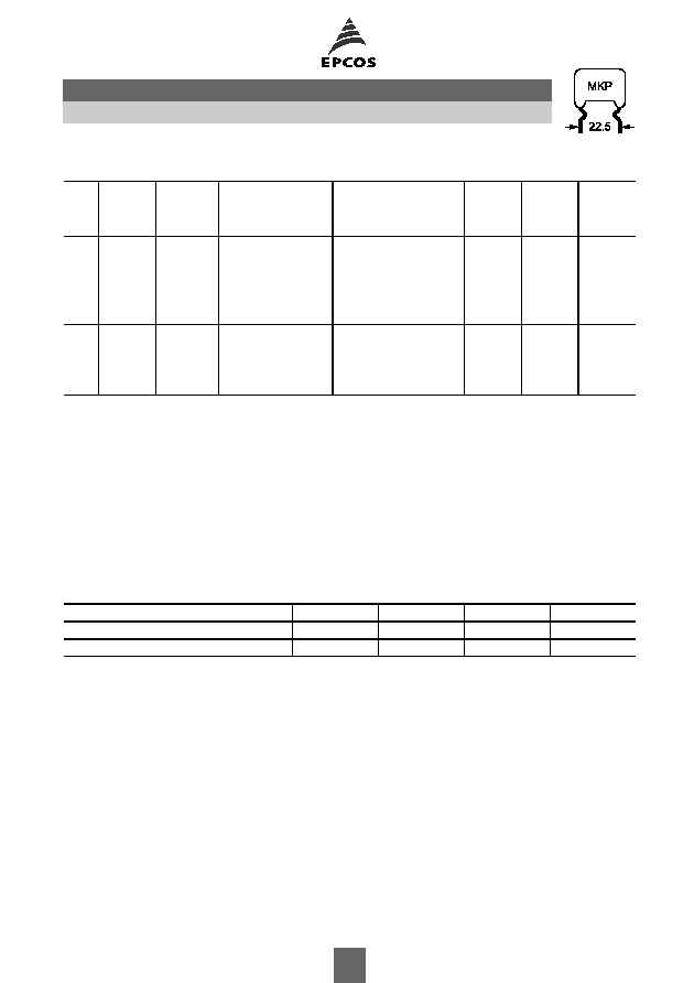
Ordering codes and packing units (lead spacing 22.5 mm)
V
R
VDC
V
rms
f
1 kHz
VAC
C
R
nF
Max. dimensions
w
◊
h
◊
l
mm
Ordering code
(composition see
below)
Ammo
pack
pcs./unit
Reel
pcs./unit
Untaped
pcs./unit
Further E series and intermediate capacitance values on request.
Composition of ordering code
+ =
Capacitance tolerance code:
*** = Packaging code:
K =
±
10%
J =
±
5%
289 = Ammo pack
189 = Reel
010 = Untaped crimped (lead length 6
1 mm)
011 = Untaped crimped (lead length min. 20 mm)
008 = Untaped (straight, lead length 17
±
3 mm)
020 = Double crimped (lead length 6
1 mm)
Packaging codes for further lead configurations (untaped):
Lead configuration (lead length 6
1 mm)
Reduced
Reduced
Reduced
Enlarged
Lead spacing (mm)
15 mm
17.5 mm
20 mm
25 mm
Packaging code
055
060
030
080
2000
700
3.3
7.0
◊
13.0
◊
26.5 B32613A2332+***
500
700
500
4.7
7.5
◊
14.0
◊
26.5 B32613A2472+***
450
650
500
6.8
8.5
◊
16.0
◊
26.5 B32613A2682+***
400
550
500
10
10.5
◊
17.0
◊
26.5 B32613A2103+***
350
450
250
15
12.0
◊
20.5
◊
26.5 B32613A2153+***
300
400
250
2000 1000
3.3
8.0
◊
14.5
◊
26.5 B32613A8332+***
450
600
500
4.7
8.5
◊
16.5
◊
26.5 B32613A8472+***
400
550
250
6.8
10.0
◊
18.5
◊
26.5 B32613A8682+***
350
500
250
10
11.5
◊
21.5
◊
26.5 B32613A8103+***
300
400
250
B32613
Pulse application (wound)
9
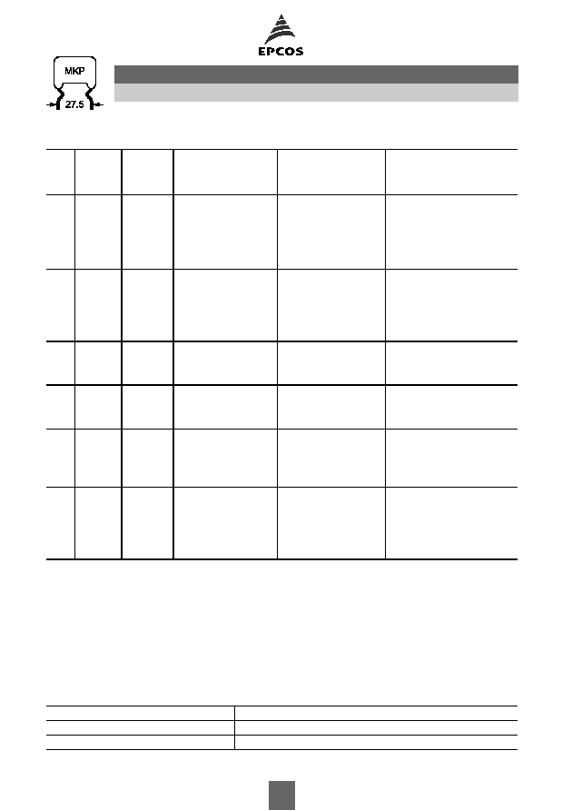
Ordering codes and packing units (lead spacing 27.5 mm)
V
R
VDC
V
rms
f
1 kHz
VAC
C
R
nF
Max. dimensions
w
◊
h
◊
l
mm
Ordering code
(composition see
below)
Untaped
pcs./unit
Further E series and intermediate capacitance values on request.
Composition of ordering code
+ =
Capacitance tolerance code:
*** = Packaging code:
K =
±
10%
J =
±
5%
010 = Untaped crimped (lead length 6
1 mm)
011 = Untaped crimped (lead length min. 20 mm)
008 = Untaped (straight, lead length 17
±
3 mm)
020 = Double crimped (lead length 6
1 mm)
Packaging codes for further lead configurations (untaped):
Lead configuration (lead length 6
1 mm)
Reduced
Lead spacing (mm)
25 mm
Packaging code
090
250 160
470
7.0
◊
15.0
◊
31.5
B32614A3474+***
500
680
8.0
◊
16.5
◊
31.5
B32614A3684+***
500
1000
9.5
◊
17.5
◊
31.5
B32614A3105+***
200
1500
11.5
◊
19.5
◊
31.5
B32614A3155+***
200
2200
14.0
◊
22.0
◊
31.5
B32614A3225+***
200
400 200
470
9.5
◊
15.0
◊
31.5
B32614A4474+***
200
680
10.0
◊
17.5
◊
31.5
B32614A4684+***
200
1000
11.5
◊
19.5
◊
31.5
B32614A4105+***
200
1500
14.0
◊
22.0
◊
31.5
B32614A4155+***
200
2200
16.5
◊
24.5
◊
31.5
B32614A4225+***
150
630 250
470
10.5
◊
18.5
◊
31.5
B32614A6474+***
200
680
12.0
◊
21.5
◊
31.5
B32614A6684+***
200
1000
14.0
◊
24.0
◊
31.5
B32614A6105+***
200
1000 250
100
11.5
◊
17.5
◊
31.5
B32614A0104+***
500
150
13.0
◊
21.0
◊
31.5
B32614A0154+***
200
220
14.5
◊
24.5
◊
31.5
B32614A0224+***
200
1600 500
22
9.0
◊
14.5
◊
31.5
B32614A1223+***
500
33
10.5
◊
16.0
◊
31.5
B32614A1333+***
500
47
11.0
◊
19.5
◊
31.5
B32614A1473+***
200
68
13.0
◊
21.5
◊
31.5
B32614A1683+***
200
2000 700
10
9.0
◊
15.5
◊
31.5
B32614A2103+***
500
15
11.0
◊
17.5
◊
31.5
B32614A2153+***
200
22
13.0
◊
19.5
◊
31.5
B32614A2223+***
200
33
14.5
◊
23.0
◊
31.5
B32614A2333+***
200
47
16.5
◊
25.5
◊
31.5
B32614A2473+***
150
B32614
Pulse application (wound)
10
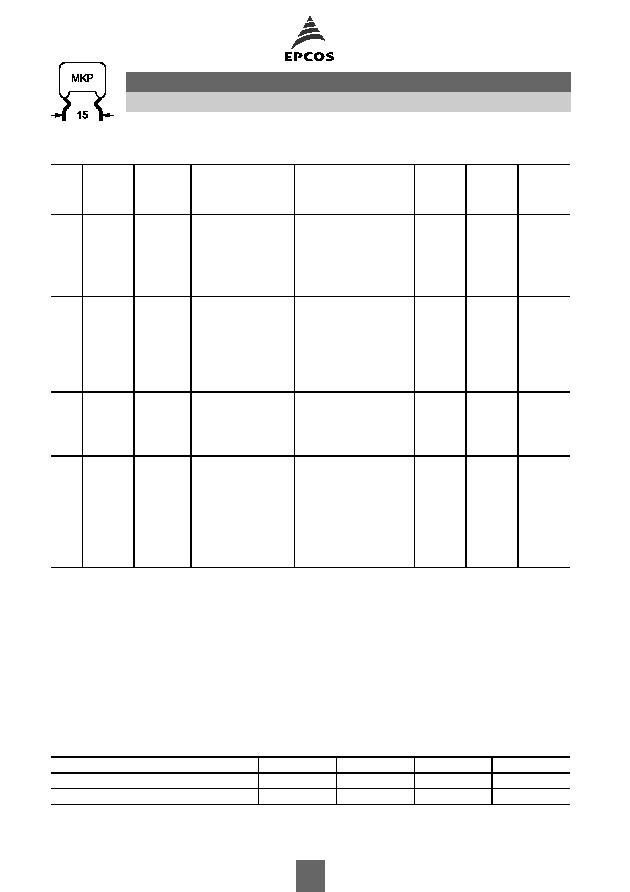
Technical data
Operating temperature range
Max. operating temperature T
op,max
+110
∞
C
Upper category temperature T
max
+100
∞
C
Lower category temperature T
min
55
∞
C
Rated temperature T
R
+85
∞
C
Dissipation factor tan
(in 10
-3
) at
C
R
0.1
µ
F
0.1
µ
F<C
R
1
µ
F
C
R
>1
µ
F
at 20
∞
C
1 kHz
0.5
0.5
(upper limit values)
10 kHz
0.8
1.5
100 kHz
5.0
Insulation resistance R
ins
C
R
0.33
µ
F
C
R
> 0.33
µ
F
or time constant
= C
R
R
ins
100 G
30000 s
at 20
∞
C, rel. humidity
65%
(minimum as-delivered values)
DC test voltage
1.6
V
R
, 2 s
Category voltage V
C
T
A
(
∞
C)
DC voltage derating
AC voltage derating
(continuous operation with V
DC
T
A
85
V
C
= V
R
V
C,rms
= V
rms
or V
AC
at f
1 kHz)
85<T
A
100
V
C
= V
R
(165 T
A
)/80
V
C,rms
=V
rms
(165 T
A
)/80
Operating voltage V
op
for
T
A
(
∞
C)
DC voltage (max. hours) AC voltage (max. hours)
short operating periods
V
op
= 1.25
V
C
(2000 h) V
op
= 1.0
V
C,rms
(2000 h)
(V
DC
or V
AC
at f
1 kHz)
V
op
= 1.25
V
C
(1000 h) V
op
= 1.0
V
C,rms
(1000 h)
Damp heat test
56 days/40
∞
C/93% relative humidity
Limit values after damp
Capacitance change
C/C
3%
heat test
Dissipation factor change
tan
0.5
10
-3
(at 1 kHz)
1.0
10
-3
(at 10 kHz)
Insulation resistance R
ins
or time constant
= C
R
R
ins
50% of minimum
as-delivered values
Reliability:
Failure rate
Service life t
SL
1 fit (
1
10
-9
/h) at 0.5
V
R
, 40
∞
C
200 000 h at 1.0
V
R
, 40
∞
C
For conversion to other operating conditions and temperatures,
refer to chapter "Quality assurance", page .
Failure criteria:
Total failure
Short circuit or open circuit
Failure due to variation
Capacitance change
C/C
> 10%
of parameters
Dissipation factor tan
> 4
upper limit value
Insulation resistance R
ins
or time constant
= C
R
R
ins
< 1500 M
(C
R
0.33
µ
F)
< 500 s (C
R
>0.33
µ
F)
B32612 ... B32614
Pulse application (wound)
11

Characteristic voltages V
DC
, V
AC
, V
pp
V
DC
V
V
AC
V
V
pp
V
1000
250
700
1250
500
1250
1600
500
1400
1600
700
1600
2000
700
1600
2000
1000
2000
B32612 ... B32614
Pulse application (wound)
12
Pulse handling capability
"dV/dt" represents the maximum permissible voltage change per unit of time for non-sinusoidal
voltages, expressed in V/
µ
s.
"k
0
" represents the maximum permissible pulse characteristic of the waveform applied to the
capacitor, expressed in V
2
/
µ
s.
Note:
The values of dV/dt and k
0
provided below must not be exceeded in order to avoid damaging the
capacitor.
dV/dt values
Lead spacing
15 mm
22.5 mm
27.5 mm
V
R
V
rms
VDC
VAC
dV/dt in V/
µ
s
250
160
140
80
50
400
200
200
100
70
630
250
270
140
100
1000
250
400
350
225
1250
500
800
1600
500
1500
1000
700
1600
700
1900
2000
700
2200
1400
900
2000
1000
2000
k
0
values
Lead spacing
15 mm
22.5 mm
27.5 mm
V
R
V
rms
VDC
VAC
k
0
in V
2
/
µ
s
250
160
70 000
40 000
25 000
400
200
160 000
80 000
55 000
630
250
340 000
170 000
120 000
1000
250
800 000
675 000
450 000
1250
500
2 000 000
1600
500
4 800 000
3 200 000
2 200 000
1600
700
6 100 000
2000
700
8 800 000
5 600 000
3 600 000
2000
1000
10 000 000
B32612 ... B32614
Pulse application (wound)
13
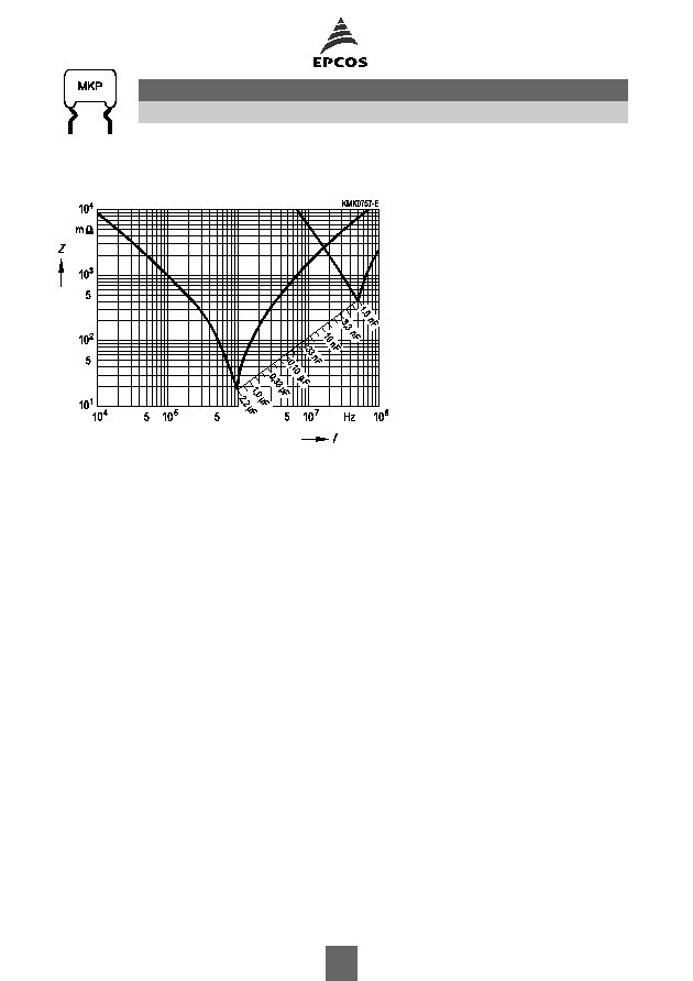
Impedance Z versus frequency f
(typical values)
B32612 ... B32614
Pulse application (wound)
14
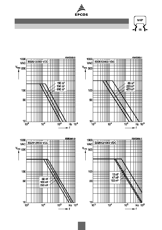
Permissible AC voltage V
rms
versus frequency f (for sinusoidal waveforms, T
A
90
∞
C)
For T
A
>90
∞
C, please refer to "General technical information", section 3.2.3.
Lead spacing 15 mm
250 VDC/160 VAC
400 VDC/200 VAC
630 VDC/250 VAC
1000 VDC/250 VAC
B32612
Pulse application (wound)
15
Permissible AC voltage V
rms
versus frequency f (for sinusoidal waveforms, T
A
90
∞
C)
For T
A
>90
∞
C, please refer to "General technical information", section 3.2.3.
Lead spacing 15 mm
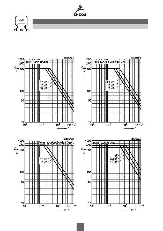
1250 VDC/500 VAC
1600 VDC/500 VAC
1600 VDC/700 VAC
2000 VDC/700 VAC
B32612
Pulse application (wound)
16

Permissible AC voltage V
rms
versus frequency f (for sinusoidal waveforms, T
A
90
∞
C)
For T
A
>90
∞
C, please refer to "General technical information", section 3.2.3.
Lead spacing 22.5 mm
250 VDC/160 VAC
400 VDC/200 VAC
630 VDC/250 VAC
1000 VDC/250 VAC
B32613
Pulse application (wound)
17

Permissible AC voltage V
rms
versus frequency f (for sinusoidal waveforms, T
A
90
∞
C)
For T
A
>90
∞
C, please refer to "General technical information", section 3.2.3.
Lead spacing 22.5 mm
1600 VDC/500 VAC
2000 VDC/700 VAC
2000 VDC/1000 VAC
B32613
Pulse application (wound)
18
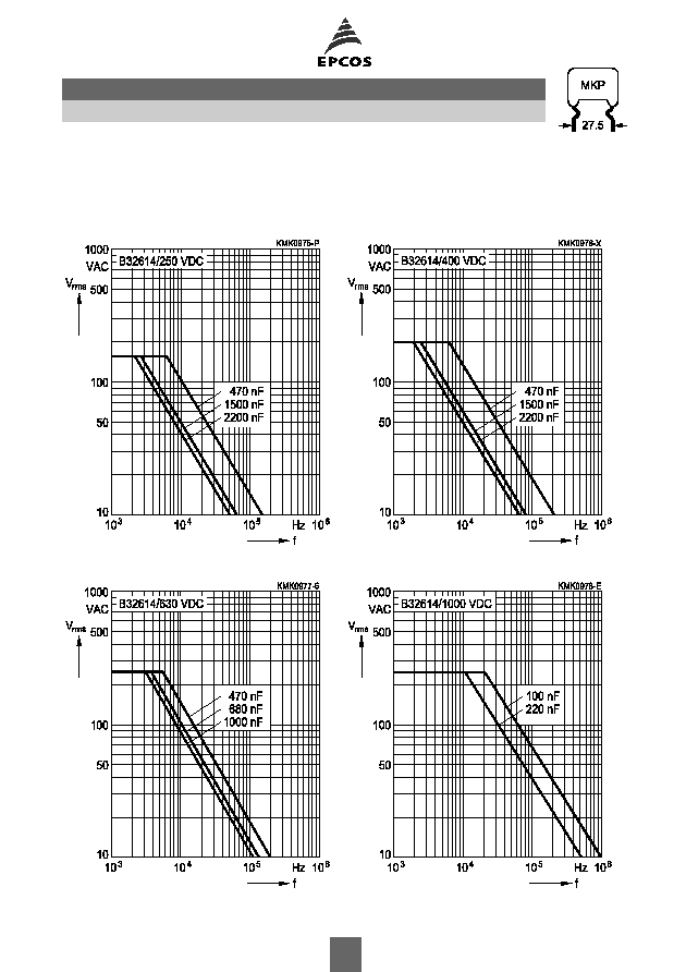
Permissible AC voltage V
rms
versus frequency f (for sinusoidal waveforms, T
A
90
∞
C)
For T
A
>90
∞
C, please refer to "General technical information", section 3.2.3.
Lead spacing 27.5 mm
250 VDC/160 VAC
400 VDC/200 VAC
630 VDC/250 VAC
1000 VDC/250 VAC
B32614
Pulse application (wound)
19
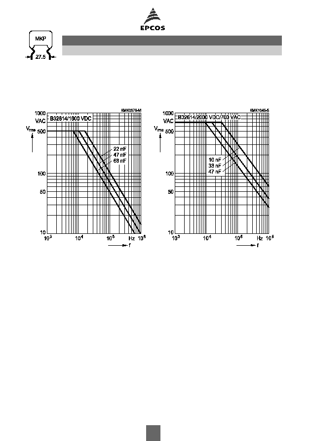
Permissible AC voltage V
rms
versus frequency f (for sinusoidal waveforms, T
A
90
∞
C)
For T
A
>90
∞
C, please refer to "General technical information", section 3.2.3.
Lead spacing 27.5 mm
1600 VDC/500 VAC
2000 VDC/700 VAC
B32614
Pulse application (wound)
20
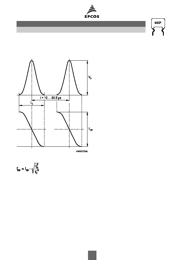
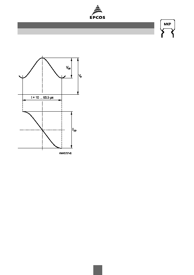
Flyback application
Permissible voltage and current / waveform
Permissible current I
pp
versus frequency f for a duty cycle of 20% (t
0
/t = 0.2):
Approximation formular for duty cycle higher than 20%:
B32612 ... B32614
Pulse application (wound)
21
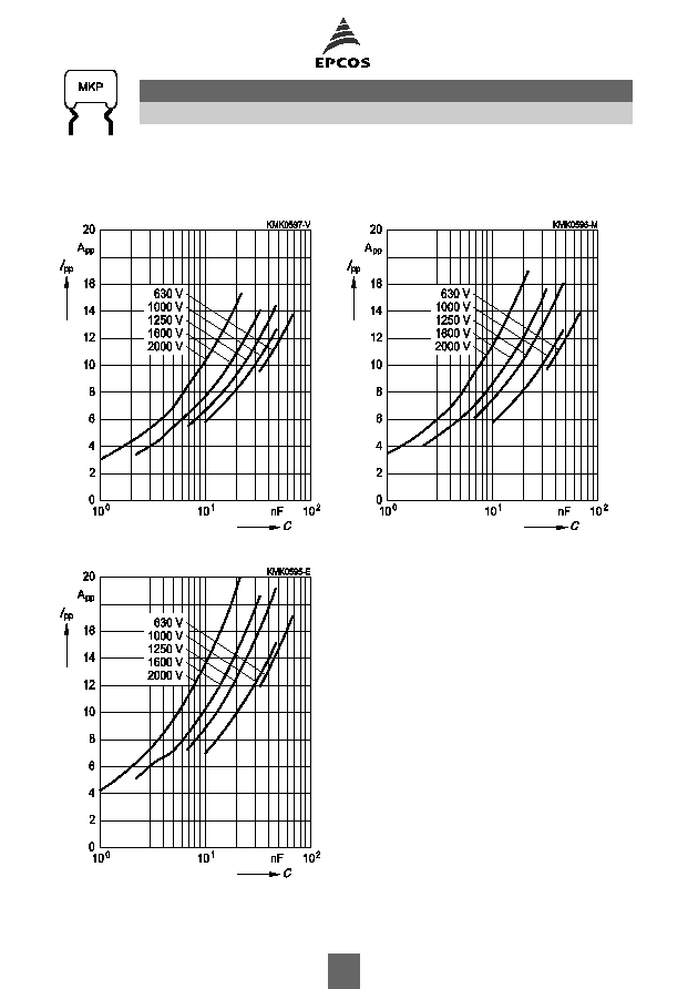
Flyback application
Permissible current I
pp
versus rated capacitance C
R
Frequency = 15.75 kHz
Frequency = 31.5 kHz
Frequency = 95 kHz
B32612 ... B32614
Pulse application (wound)
22
S-correction application
Permissible voltage and current / waveform
B32612 ... B32614
Pulse application (wound)
23

S-correction application
Permissible current I
pp
versus rated capacitance C
R
Frequency = 15.75 kHz
Frequency = 31.75 kHz
Frequency = 95 kHz
B32612 ... B32614
Pulse application (wound)
24