
Film Capacitors
Metallized Polypropylene Film Capacitors (MFP)
Series/Type:
B32686S
Date:
August 2004
© EPCOS AG 2004. Reproduction, publication and dissemination of this data sheet, enclosures hereto and the
information contained therein without EPCOS' prior express consent is prohibited.
Purchase orders are subject to the General Conditions for the Supply of Products and Services of the Electrical
and Electronics Industry recommended by the ZVEI (German Electrical and Electronic Manufacturers' Associ-
ation), unless otherwise agreed.

Typical applications
Snubbering
Filtering
IGBT
Climatic
Max. operating temperature: 100
∞
C
Climatic category (IEC 60068-1): 55/100/56
Construction
Dielectric: polypropylene (PP)
Film metallized on one side and
metal foils internally connected in series
Plastic case, epoxy resin sealing (UL 94 V-0)
Features
Very high pulse strength
High current
Highest possible contact reliability
Terminals
Strap terminals, tinned copper (max. torque 10 Nm)
Marking
Manufacturer's logo, ordering code, style (MFP)
rated capaitance (coded), cap. tolerance (code letter),
rated DC voltage, date of manufacture (coded)
Delivery mode: Bulk
Dimensional drawings
T1 (code no. 561)
T2 (code no. 562)
Metallized polypropylene film capacitors (MFP)
B32686S
Snubbering (wound)
2
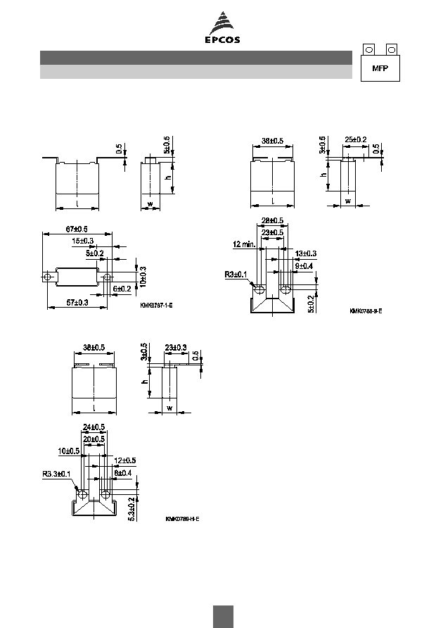
Dimensional drawings (continued)
T3 (code no. 563)
T4 (code no. 564)
T5 (code no. 565)
B32686S
Snubbering (wound)
3

Overview of available types
Type
B32686S
V
R
(VDC)
1000
1250
1600
2000
V
rms
(VAC)
400
450
450
500
C
R
(nF)
22
33
47
68
100
120
150
220
270
330
390
470
560
680
B32686S
Snubbering (wound)
4
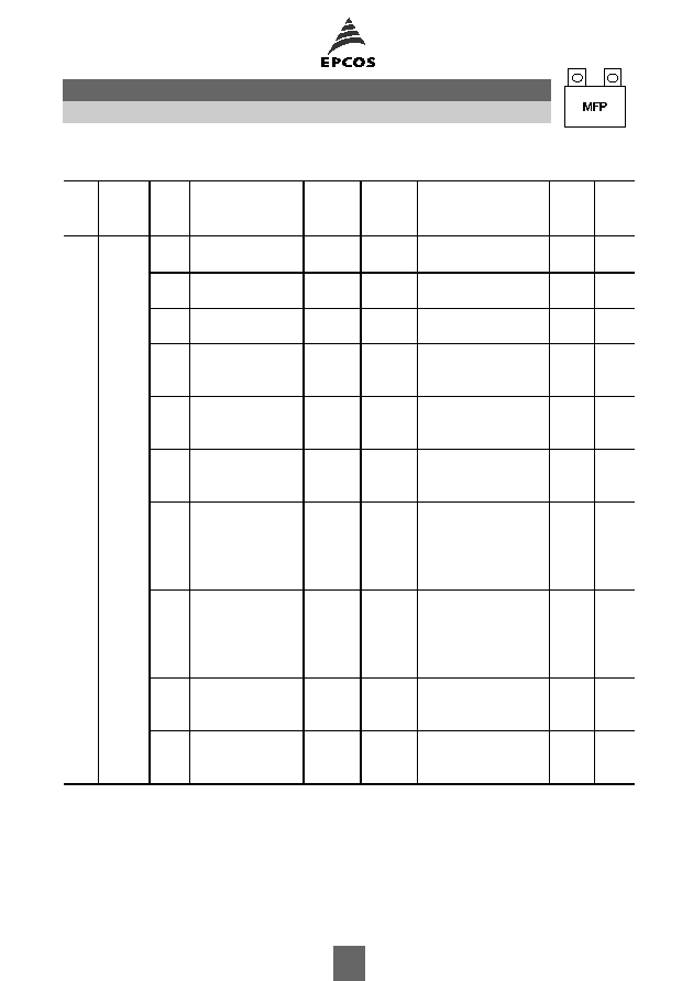
Electrical specifications, ordering codes and packing units
V
R
VDC
V
rms
f
1kHz
VAC
C
R
nF
Max. dimensions
w
◊
h
◊
l
mm
I
rms
100 kHz
A
ESR
100 kHz
m
Ordering code
(composition see
below)
Ter-
minal
pcs./
unit
Further E series and intermediate capacitance values on request.
Composition of ordering code
+ =
Capacitance tolerance code:
M =
±
20%
K =
±
10%
J =
±
5%
1000 400
68
12.0
◊
22.5
◊
42.0
4.0
20
B32686S0683+563
T3
56
68
12.0
◊
22.5
◊
42.0
4.0
20
B32686S0683+564
T4
96
100
12.0
◊
22.5
◊
42.0
4.5
15
B32686S0104+563
T3
56
100
12.0
◊
22.5
◊
42.0
4.5
15
B32686S0104+564
T4
96
120
12.0
◊
22.5
◊
42.0
4.5
13
B32686S0124+563
T3
56
120
12.0
◊
22.5
◊
42.0
4.5
13
B32686S0124+564
T4
96
150
14.0
◊
25.0
◊
42.0
5.5
10
B32686S0154+563
T3
48
150
14.0
◊
25.0
◊
42.0
5.5
10
B32686S0154+564
T4
72
150
14.0
◊
25.0
◊
42.0
5.5
10
B32686S0154+565
T5
72
220
16.0
◊
28.5
◊
42.0
7.0
7
B32686S0224+563
T3
40
220
16.0
◊
28.5
◊
42.0
7.0
7
B32686S0224+564
T4
48
220
16.0
◊
28.5
◊
42.0
7.0
7
B32686S0224+565
T5
48
270
18.0
◊
32.5
◊
42.0
7.5
7
B32686S0274+563
T3
36
270
18.0
◊
32.5
◊
42.0
7.5
7
B32686S0274+564
T4
32
270
18.0
◊
32.5
◊
42.0
7.5
7
B32686S0274+565
T5
32
330
20.0
◊
39.5
◊
42.0
8.5
5
B32686S0334+561
T1
24
330
20.0
◊
39.5
◊
42.0
8.5
5
B32686S0334+562
T2
24
330
20.0
◊
39.5
◊
42.0
8.5
5
B32686S0334+563
T3
26
330
20.0
◊
39.5
◊
42.0
8.5
5
B32686S0334+564
T4
24
330
20.0
◊
39.5
◊
42.0
8.5
5
B32686S0334+565
T5
24
390
20.0
◊
39.5
◊
42.0
9.0
5
B32686S0394+561
T1
24
390
20.0
◊
39.5
◊
42.0
9.0
5
B32686S0394+562
T2
24
390
20.0
◊
39.5
◊
42.0
9.0
5
B32686S0394+563
T3
26
390
20.0
◊
39.5
◊
42.0
9.0
5
B32686S0394+564
T4
24
390
20.0
◊
39.5
◊
42.0
9.0
5
B32686S0394+565
T5
24
470
28.0
◊
37.0
◊
42.0 10.0
3
B32686S0474+561
T1
27
470
28.0
◊
37.0
◊
42.0 10.0
3
B32686S0474+562
T2
27
470
28.0
◊
37.0
◊
42.0 10.0
3
B32686S0474+563
T3
18
560
28.0
◊
37.0
◊
42.0 11.0
3
B32686S0564+561
T1
27
560
28.0
◊
37.0
◊
42.0 11.0
3
B32686S0564+562
T2
27
560
28.0
◊
37.0
◊
42.0 11.0
3
B32686S0564+563
T3
18
B32686S
Snubbering (wound)
5

Electrical specifications, ordering codes and packing units
V
R
VDC
V
rms
f
1kHz
VAC
C
R
nF
Max. dimensions
w
◊
h
◊
l
mm
I
rms
100 kHz
A
ESR
100 kHz
m
Ordering code
(composition see
below)
Ter-
minal
pcs./
unit
Further E series and intermediate capacitance values on request.
Composition of ordering code
+ =
Capacitance tolerance code:
M =
±
20%
K =
±
10%
J =
±
5%
1000 400
680
30.0
◊
45.0
◊
42.0 12.0
3
B32686S0684+561
T1
12
680
30.0
◊
45.0
◊
42.0 12.0
3
B32686S0684+562
T2
12
680
30.0
◊
45.0
◊
42.0 12.0
3
B32686S0684+563
T3
18
1250 450
68
12.0
◊
22.5
◊
42.0
4.5
20
B32686S7683+563
T3
56
68
12.0
◊
22.5
◊
42.0
4.5
20
B32686S7683+564
T4
96
100
14.0
◊
25.0
◊
42.0
5.0
15
B32686S7104+563
T3
48
100
14.0
◊
25.0
◊
42.0
5.0
15
B32686S7104+564
T4
72
100
14.0
◊
25.0
◊
42.0
5.0
15
B32686S7104+565
T5
72
120
14.0
◊
25.0
◊
42.0
5.5
13
B32686S7124+563
T3
48
120
14.0
◊
25.0
◊
42.0
5.5
13
B32686S7124+564
T4
72
120
14.0
◊
25.0
◊
42.0
5.5
13
B32686S7124+565
T5
72
150
16.0
◊
28.5
◊
42.0
6.5
10
B32686S7154+563
T3
40
150
16.0
◊
28.5
◊
42.0
6.5
10
B32686S7154+564
T4
48
150
16.0
◊
28.5
◊
42.0
6.5
10
B32686S7154+565
T5
48
220
18.0
◊
32.5
◊
42.0
8.5
7
B32686S7224+563
T3
36
220
18.0
◊
32.5
◊
42.0
8.5
7
B32686S7224+564
T4
32
220
18.0
◊
32.5
◊
42.0
8.5
7
B32686S7224+565
T5
32
270
20.0
◊
39.5
◊
42.0
9.0
7
B32686S7274+561
T1
24
270
20.0
◊
39.5
◊
42.0
9.0
7
B32686S7274+562
T2
24
270
20.0
◊
39.5
◊
42.0
9.0
7
B32686S7274+563
T3
26
270
20.0
◊
39.5
◊
42.0
9.0
7
B32686S7274+564
T4
24
270
20.0
◊
39.5
◊
42.0
9.0
7
B32686S7274+565
T5
24
330
28.0
◊
37.0
◊
42.0 10.0
5
B32686S7334+561
T1
27
330
28.0
◊
37.0
◊
42.0 10.0
5
B32686S7334+562
T2
27
330
28.0
◊
37.0
◊
42.0 10.0
5
B32686S7334+563
T3
18
390
28.0
◊
37.0
◊
42.0 11.0
5
B32686S7394+561
T1
27
390
28.0
◊
37.0
◊
42.0 11.0
5
B32686S7394+562
T2
27
390
28.0
◊
37.0
◊
42.0 11.0
5
B32686S7394+563
T3
18
470
30.0
◊
45.0
◊
42.0 12.0
5
B32686S7474+561
T1
12
470
30.0
◊
45.0
◊
42.0 12.0
5
B32686S7474+562
T2
12
470
30.0
◊
45.0
◊
42.0 12.0
5
B32686S7474+563
T3
18
B32686S
Snubbering (wound)
6

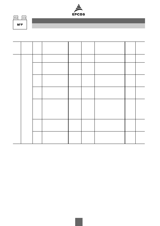
Electrical specifications, ordering codes and packing units
V
R
VDC
V
rms
f
1kHz
VAC
C
R
nF
Max. dimensions
w
◊
h
◊
l
mm
I
rms
100 kHz
A
ESR
100 kHz
m
Ordering code
(composition see
below)
Ter-
minal
pcs./
unit
Further E series and intermediate capacitance values on request.
Composition of ordering code
+ =
Capacitance tolerance code:
M =
±
20%
K =
±
10%
J =
±
5%
1600 450
47
12.0
◊
22.5
◊
42.0
5.0
30
B32686S1473+563
T3
56
47
12.0
◊
22.5
◊
42.0
5.0
30
B32686S1473+564
T4
96
68
14.0
◊
25.0
◊
42.0
6.0
20
B32686S1683+563
T3
48
68
14.0
◊
25.0
◊
42.0
6.0
20
B32686S1683+564
T4
72
68
14.0
◊
25.0
◊
42.0
6.0
20
B32686S1683+565
T5
72
100
18.0
◊
32.5
◊
42.0
7.0
15
B32686S1104+563
T3
36
100
18.0
◊
32.5
◊
42.0
7.0
15
B32686S1104+564
T4
32
100
18.0
◊
32.5
◊
42.0
7.0
15
B32686S1104+565
T5
32
120
18.0
◊
32.5
◊
42.0
7.5
13
B32686S1124+563
T3
36
120
18.0
◊
32.5
◊
42.0
7.5
13
B32686S1124+564
T4
32
120
18.0
◊
32.5
◊
42.0
7.5
13
B32686S1124+565
T5
32
150
20.0
◊
39.5
◊
42.0
8.5
10
B32686S1154+561
T1
24
150
20.0
◊
39.5
◊
42.0
8.5
10
B32686S1154+562
T2
24
150
20.0
◊
39.5
◊
42.0
8.5
10
B32686S1154+563
T3
26
150
20.0
◊
39.5
◊
42.0
8.5
10
B32686S1154+564
T4
24
150
20.0
◊
39.5
◊
42.0
8.5
10
B32686S1154+565
T5
24
220
28.0
◊
37.0
◊
42.0 10.5
7
B32686S1224+561
T1
27
220
28.0
◊
37.0
◊
42.0 10.5
7
B32686S1224+562
T2
27
220
28.0
◊
37.0
◊
42.0 10.5
7
B32686S1224+563
T3
18
270
30.0
◊
45.0
◊
42.0 11.5
7
B32686S1274+561
T1
12
270
30.0
◊
45.0
◊
42.0 11.5
7
B32686S1274+562
T2
12
270
30.0
◊
45.0
◊
42.0 11.5
7
B32686S1274+563
T3
18
B32686S
Snubbering (wound)
7
Electrical specifications, ordering codes and packing units
V
R
VDC
V
rms
f
1kHz
VAC
C
R
nF
Max. dimensions
w
◊
h
◊
l
mm
I
rms
100 kHz
A
ESR
100 kHz
m
Ordering code
(composition see
below)
Ter-
minal
pcs./
unit
Further E series and intermediate capacitance values on request.
Composition of ordering code
+ =
Capacitance tolerance code:
M =
±
20%
K =
±
10%
J =
±
5%
2000 500
22
12.0
◊
22.5
◊
42.0
4.0
70
B32686S2223+563
T3
56
22
12.0
◊
22.5
◊
42.0
4.0
70
B32686S2223+564
T4
96
33
14.0
◊
25.0
◊
42.0
5.0
50
B32686S2333+563
T3
48
33
14.0
◊
25.0
◊
42.0
5.0
50
B32686S2333+564
T4
72
33
14.0
◊
25.0
◊
42.0
5.0
50
B32686S2333+565
T5
72
47
16.0
◊
28.5
◊
42.0
6.0
30
B32686S2473+563
T3
40
47
16.0
◊
28.5
◊
42.0
6.0
30
B32686S2473+564
T4
48
47
16.0
◊
28.5
◊
42.0
6.0
30
B32686S2473+565
T5
48
68
18.0
◊
32.5
◊
42.0
7.5
20
B32686S2683+563
T3
36
68
18.0
◊
32.5
◊
42.0
7.5
20
B32686S2683+564
T4
32
68
18.0
◊
32.5
◊
42.0
7.5
20
B32686S2683+565
T5
32
100
20.0
◊
39.5
◊
42.0
8.5
15
B32686S2104+561
T1
24
100
20.0
◊
39.5
◊
42.0
8.5
15
B32686S2104+562
T2
24
100
20.0
◊
39.5
◊
42.0
8.5
15
B32686S2104+563
T3
26
100
20.0
◊
39.5
◊
42.0
8.5
15
B32686S2104+564
T4
24
100
20.0
◊
39.5
◊
42.0
8.5
15
B32686S2104+565
T5
24
120
28.0
◊
37.0
◊
42.0
9.0
13
B32686S2124+561
T1
24
120
28.0
◊
37.0
◊
42.0
9.0
13
B32686S2124+562
T2
24
120
28.0
◊
37.0
◊
42.0
9.0
13
B32686S2124+563
T3
26
150
28.0
◊
37.0
◊
42.0 10.0
10
B32686S2154+561
T1
27
150
28.0
◊
37.0
◊
42.0 10.0
10
B32686S2154+562
T2
27
150
28.0
◊
37.0
◊
42.0 10.0
10
B32686S2154+563
T3
18
B32686S
Snubbering (wound)
8

Technical data
Operating temperature range
Max. operating temperature T
op,max
+100
∞
C
Upper category temperature T
max
+100
∞
C
Lower category temperature T
min
55
∞
C
Rated temperature T
R
+85
∞
C
Dissipation factor tan
1.0
10
-3
(at 10 kHz)
at 20
∞
C
3.0
10
-3
(at 10 kHz)
(upper limit values)
Insulation resistance R
ins
C
R
0.33
µ
F
C
R
> 0.33
µ
F
or time constant
= C
R
R
ins
100 G
30000 s
at 20
∞
C, rel. humidity
65%
(minimum as-delivered values)
DC test voltage
2.0
V
R
, 2 s
Category voltage V
C
T
A
(
∞
C)
DC voltage derating
AC voltage derating
(continuous operation with V
DC
T
A
85
V
C
= V
R
V
C,rms
= V
rms
or V
AC
at f
1 kHz)
85<T
A
100
V
C
= V
R
(165 T
A
)/80
V
C,rms
=V
rms
(165 T
A
)/80
Operating voltage V
op
for
T
A
(
∞
C)
DC voltage (max. hours) AC voltage (max. hours)
short operating periods
T
A
85
V
op
= 1.25
V
C
(2000 h) V
op
= 1.0
V
C,rms
(2000 h)
(V
DC
or V
AC
at f
1 kHz)
85<T
A
100
V
op
= 1.25
V
C
(1000 h) V
op
= 1.0
V
C,rms
(1000 h)
Damp heat test
56 days/40
∞
C/93% relative humidity
Limit values after damp
Capacitance change
C/C
2%
heat test
Dissipation factor change
tan
1.0
10
-3
(at 10 kHz)
Insulation resistance R
ins
or time constant
= C
R
R
ins
50% of minimum
as-delivered values
Reliability:
Failure rate
1 fit (
1
10
-9
/h) at 0.5
V
R
, 40
∞
C
Service life t
SL
200 000 h at 1.0
V
R
, 40
∞
C
For conversion to other operating conditions and temperatures,
refer to chapter "Quality assurance", page .
Failure criteria:
Total failure
Short circuit or open circuit
Failure due to variation
Capacitance change
C/C
> 10%
of parameters
Dissipation factor tan
4
upper limit value
Insulation resistance R
ins
or time constant
= C
R
R
ins
< 1500 M
(C
R
0.33
µ
F)
< 500 s (C
R
>0.33
µ
F)
B32686S
Snubbering (wound)
9

Pulse handling capability
"dV/dt" represents the maximum permissible voltage change per unit of time for non-sinusoidal
voltages, expressed in V/
µ
s.
"k
0
" represents the maximum permissible pulse characteristic of the waveform applied to the
capacitor, expressed in V
2
/
µ
s.
Note:
The values of dV/dt and k
0
provided below must not be exceeded in order to avoid damaging the
capacitor.
dV/dt and k
0
values
V
R
(VDC)
V
rms
(VAC)
dV/dt in V/
µ
s
k
0
in V
2
/
µ
s
1000
400
2 000
4 000 000
1250
450
2 800
7 000 000
1600
450
3 500
11 000 000
2000
500
4 500
18 000 000
Impedance Z versus frequency f
(typical values)
B32686S
Snubbering (wound)
10
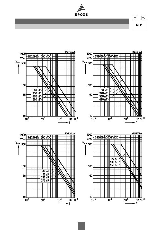
Permissible AC voltage V
rms
versus frequency f (for sinusoidal waveforms, T
A
90
∞
C)
For T
A
>90
∞
C, please refer to "General technical information", section 3.2.3.
1000 VDC/400 VAC
1250 VDC/450 VAC
1600 VDC/450 VAC
2000 VDC/500 VAC
B32686S
Snubbering (wound)
11