
Data Sheet
Data Sheet
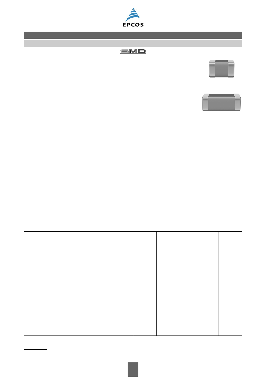
Multilayer ceramic capacitors
Date:
October 2006
„ EPCOS AG 2006. Reproduction, publication and dissemination of this data sheet and the
information contained therein without EPCOS' prior express consent is prohibited.
Chip capacitors, C0G
2
10/06
Please read Cautions and warnings and
Important notes at the end of this document.
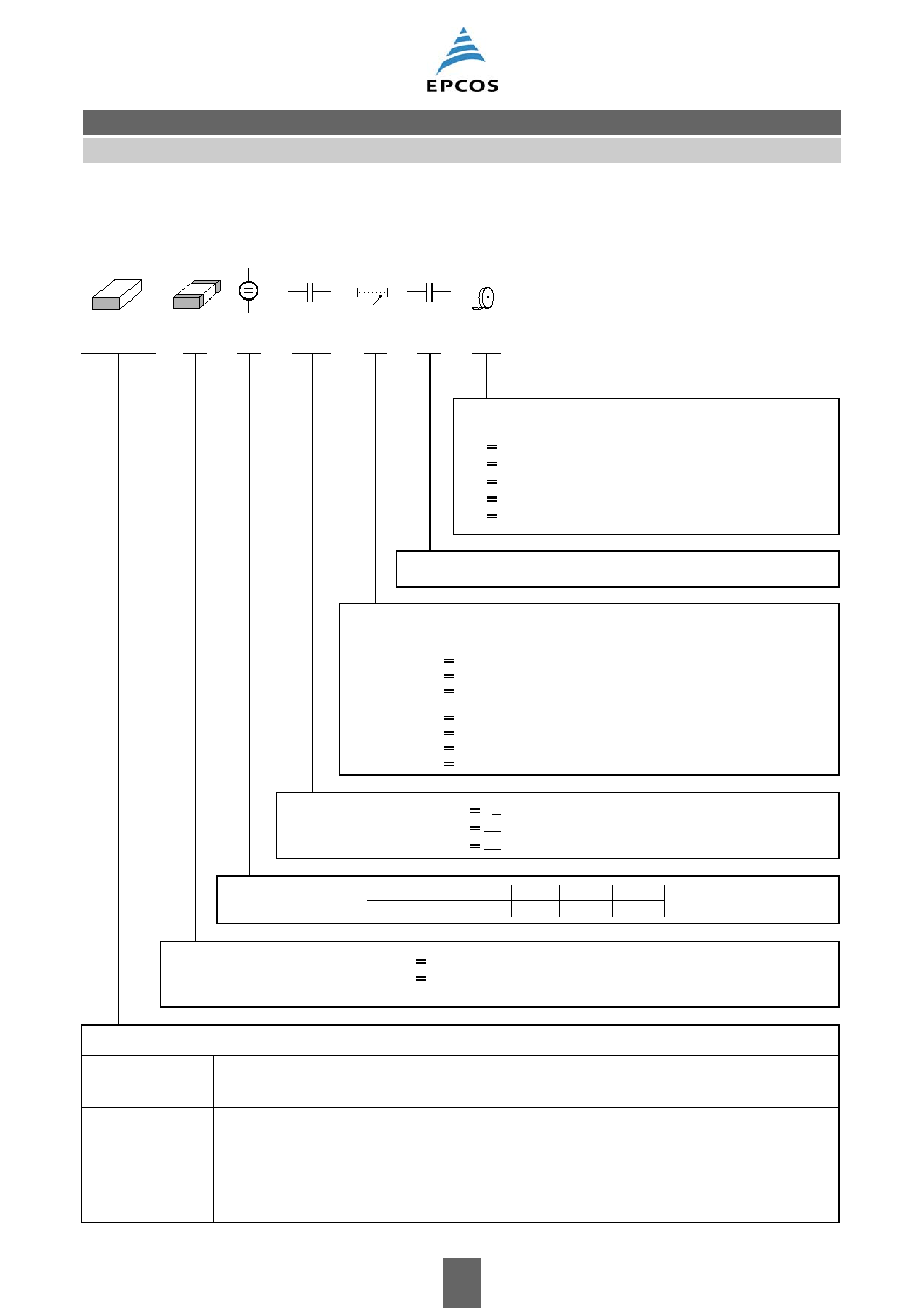
Ordering code system
B37940
K
5
010
C
5
60
Packaging
60
cardboard tape, 180-mm reel
62
blister tape, 180-mm reel
70
cardboard tape, 330-mm reel
72
blister tape, 330-mm reel
01
bulk case
^
^
^
^
^
Decimal place for cap. values <10 pF, otherwise 0
Capacitance tolerance
B
±0.1 pF
C
±0.25 pF (standard for capacitance values 4.7 pF)
D
±0.5 pF (standard for capacitance values 8.2 pF)
^
^
^
F
± 1%
G
± 2%
J
± 5% (standard)
K
±10%
^
^
^
^
C
R
<10 pF:
C
R
≥10 pF:
Capacitance, coded
(example)
010
1 ∑ 10
0
pF =
1 pF
100
10 ∑ 10
0
pF = 10 pF
221
22 ∑ 10
1
pF = 220 pF
^
^
^
Rated voltage
Rated voltage [VDC]
Code
50
100
200
5
1
2
Termination
Type and size
Chip size
(inch / mm)
0402 / 1005
0603 / 1608
0805 / 2012
1206 / 3216
1210 / 3225
Temperature characteristic
C0G
B37920
B37930
B37940
B37871
B37949
Standard:
On request:
K
nickel barrier for all case sizes
J
silver-palladium for conductive adhesion: all case sizes
^
^
Chip
C0G
Multilayer ceramic capacitors
3
10/06
Please read Cautions and warnings and
Important notes at the end of this document.
Features
Good thermal stability
High insulation resistance
Low dissipation factor
Low inductance
To AEC-Q200
Applications
Resonant circuits
Filter circuits
Timing elements
Coupling and filtering, particularly in RF circuits
Termination
For soldering: Nickel barrier terminations (Ni)
For conductive adhesion: Silver-palladium terminations (AgPd) on request
Options
Alternative capacitance tolerances available on request
Delivery mode
Cardboard and blister tape (blister tape for chip thickness
≥1.2 ±0.1 mm and case size 1210),
180-mm and 330-mm reel available
Bulk case for case sizes 0402, 0603 (50 V) and 0805 (50 V) on request
Electrical data
Temperature characteristic
C0G
Climatic category (IEC 60068-1)
55/125/56
Standard
EIA
Dielectric
Class 1
Rated voltage
V
R
50, 100, 200
VDC
Test voltage
V
test
2.5 ∑ V
R
/5 s
VDC
Capacitance range / E series
C
R
1 pF ... 10 nF (E6/E12)
Temperature coefficient
0
± 30 ∑ 10
≠6
/K
Dissipation factor (limit value)
tan
d
<1.0 ∑ 10
≠3
Insulation resistance
1)
at + 25
∞C
R
ins
>10
5
M
W
Insulation resistance
1)
at +125
∞C
R
ins
>10
4
M
W
Time constant
1)
at + 25
∞C
t >1000
s
Time constant
1)
at +125
∞C
t >100
s
Operating temperature range
T
op
≠55 ... +125
∞C
Ageing
none
1) For C
R
>10 nF the time constant
t = C ∑ R
ins
is given.
Chip
C0G
Multilayer ceramic capacitors
Multilayer ceramic capacitors
4
10/06
C0G
Please read Cautions and warnings and
Important notes at the end of this document.
Capacitance tolerances
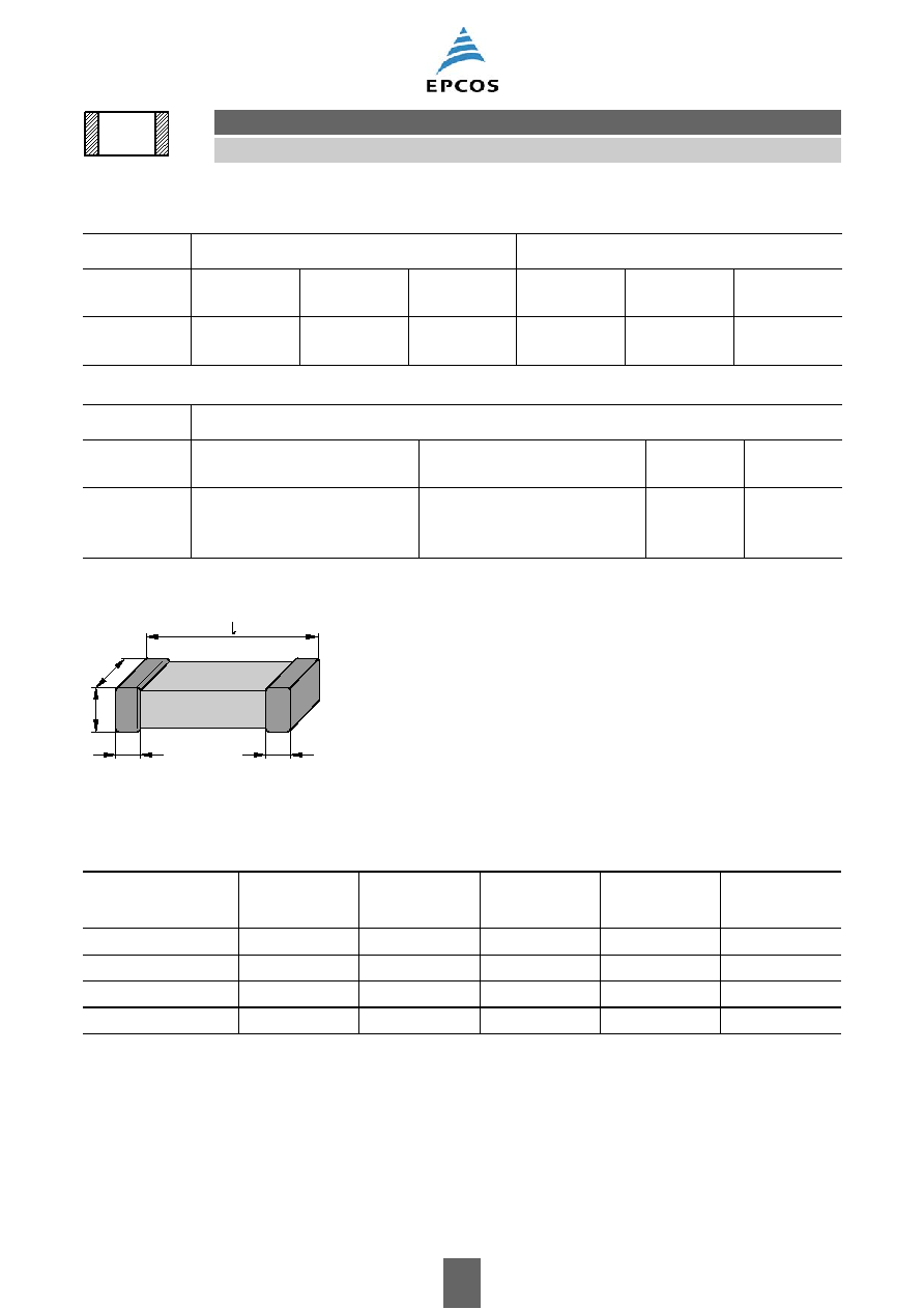
Dimensional drawing
Dimensions (mm)
Tolerances to CECC 32101-801
C
R
£ 4.7 pF
5.6 pF
£ C
R
£ 8.2 pF
Code letter
B
C
(standard)
D
B
C
D
(standard)
Tolerance
±0.1 pF
(on request)
±0.25 pF
±0.5 pF
±0.1 pF
(on request)
±0.25 pF
(on request)
±0.5 pF
C
R
≥ 10 pF
Code letter
F
G
J
(standard)
K
Tolerance
±1% (on request for 50 V
and 100 V; not available for
200 V)
±2% (on request for 50 V
and 100 V; not available for
200 V)
±5%
±10%
Case size
(inch)
(mm)
0402
1005
0603
1608
0805
2012
1206
3216
1210
3225
l
1.0
±0.10
1.6
±0.15
2.00
±0.20
3.20
±0.20
3.20
±0.30
b
0.5
±0.05
0.8
±0.10
1.25
±0.15
1.60
±0.15
2.50
±0.30
s
0.5
±0.05
0.8
±0.10
1.30 max.
1.30 max.
1.70 max.
k
0.1 ≠0.40
0.1 ≠0.40
0.13 ≠0.75
0.25 ≠0.75
0.25 ≠0.75
KKE0329-N
k
s
b
k
C0G
Multilayer ceramic capacitors
5
10/06
C0G
Please read Cautions and warnings and
Important notes at the end of this document.
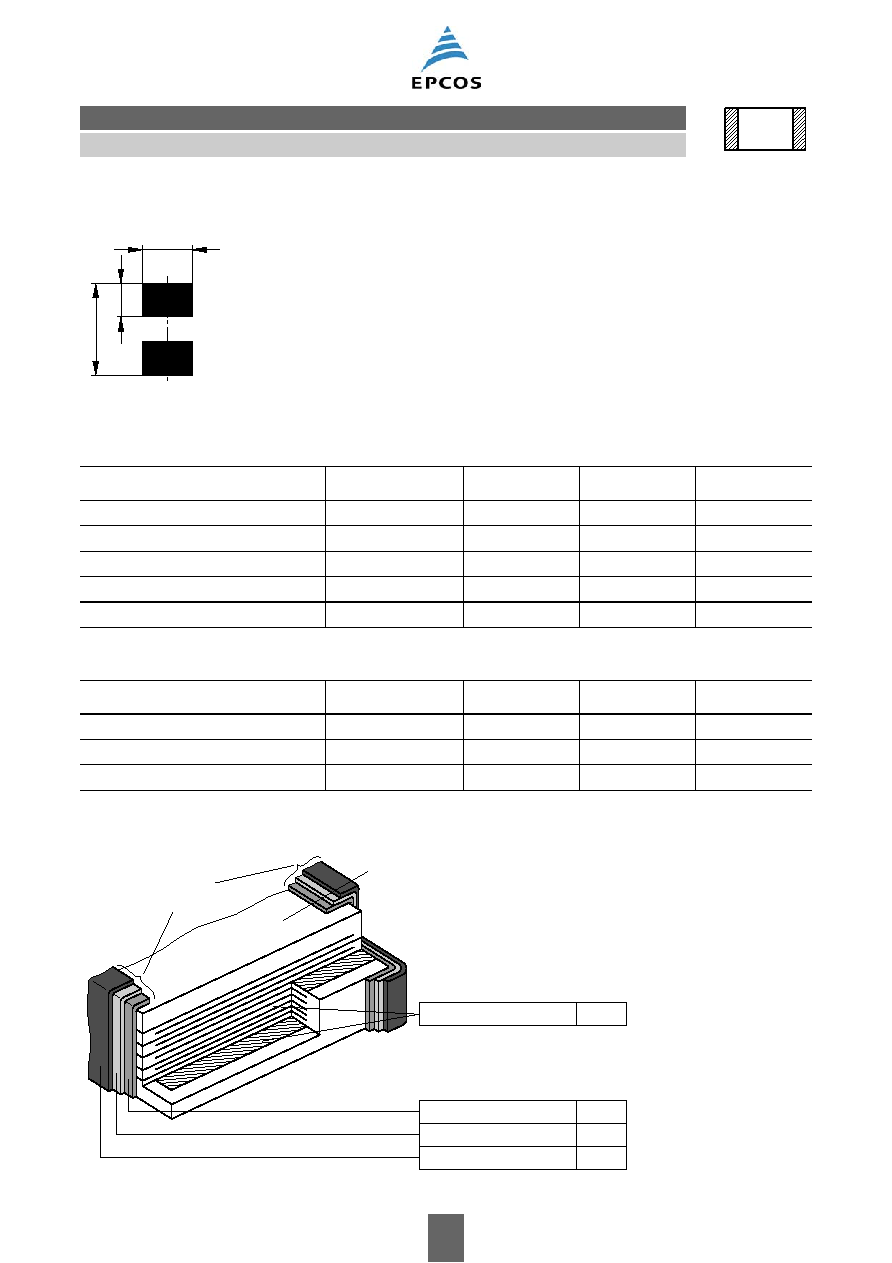
Recommended solder pad
Recommended dimensions (mm) for reflow soldering
Recommended dimensions (mm) for wave soldering
Termination
Case size
(inch/mm)
Type
A
C
D
0402/1005
single chip
0.35 ... 0.45
1.0 ... 1.40
0.4 ... 0.6
0603/1608
single chip
0.60 ... 0.70
1.8 ... 2.20
0.6 ... 0.8
0805/2012
single chip
0.60 ... 0.70
2.2 ... 2.60
0.8 ... 1.1
1206/3216
single chip
0.80 ... 0.90
3.8 ... 4.32
1.0 ... 1.4
1210/3225
single chip
1.00 ... 1.20
4.0 ... 4.80
1.8 ... 2.3
Case size
(inch/mm)
Type
A
C
D
0603/1608
single chip
0.8 ... 0.9
2.2 ... 2.8
0.6 ... 0.8
0805/2012
single chip
0.9 ... 1.0
2.8 ... 3.2
0.8 ... 1.1
1206/3216
single chip
1.0 ... 1.1
4.2 ... 4.8
1.0 ... 1.4
KKE0308-1
D
A
C
External electrode
Intermediate electrode
Substrate electrode
KKE0484-W
Ni
Sn
Ag
Inner electrode
AgPd
Termination
(nickel barrier)
Ceramic body
C0G