
Data Sheet
Data Sheet
Multilayer ceramic capacitors
Date:
October 2006
„ EPCOS AG 2006. Reproduction, publication and dissemination of this data sheet and the
information contained therein without EPCOS' prior express consent is prohibited.
Chip capacitors, Advanced series, C0G and X7R

2
10/06
Please read Cautions and warnings and
Important notes at the end of this document.
General
Criteria for high reliability
For both OEMs and component manufacturers, high reliability is assured by consistent process
control. If it is assumed that the component manufacturer supplies a defect-free product, then fur-
ther correct processing by the customer forms the basis for perfect operation of the components
and thus the entire application. So the precondition for high quality is not exclusively a particular
"intermediate product" (such as the ceramic capacitor) but rather the process control along the
entire production chain up to its end point. This requires a high degree of mutual process under-
standing between the various partners (e.g. component manufacturer and placement operator) and
the formulation of joint quality guidelines.
AEC-Q200 is a standard for quality requirements on components in various technologies. In view
of its general character, AEC-Q200 does not apply to every component to the same extent and thus
defines a minimum requirement on quality. AEC-Q200 stipulates the observance of limits that can
be checked by means of a good/bad decision. It therefore permits a qualitative statement but not a
quantitative one. However, it is precisely the latter that is important if we wish to approach "zero
defects". So process control moves to center stage and becomes the decisive element for ensuring
and continuously improving the maximum possible reliability.
EPCOS has implemented this paradigm change and thus laid the foundation for a zero defect strat-
egy. This concept is integrated in the "ppb level assurance system" and is particularly realized and
continuously developed further in the Advanced series.
The requirements made on the Advanced series exceed those of AEC-Q200. The criteria are clearly
oriented to the aim of achieving "zero defects". An important precondition for high component reli-
ability is the production of the ceramic powder at our own plant. Only by knowing all the inter-
relationships and effects from the raw material to the completed component can the self-imposed
quality criteria actually be implemented in all production steps. EPCOS has been developing and
manufacturing its own ceramic powder for ceramic capacitors for many years so that the component
quality can be assured from the first step of manufacture.
ppb level assurance system
The precondition for reliability at ppb level is, apart from process knowledge, a high degree of pro-
cess control. To achieve this, the entire production process is subdivided systematically into sub-
processes that are continuously checked with static methods on the basis of quantifiable parame-
ters. These analysis methods are used by EPCOS within the scope of the Advanced series for all
production steps from ceramic powder production and component design up to the 100% electrical
testing.
Chip
Advanced series
Multilayer ceramic capacitors

3
10/06
Please read Cautions and warnings and
Important notes at the end of this document.
In summary, the ppb level assurance system involves the following points:
Statistical methods for component design and process control
Use of the Weibull method for statistical data analysis
Introduction of quantifiable parameters (such as the failure time) to replace the previous "good"
or "bad" decisions
Dynamic test limits as a complement to fixed limits in the 100% electrical test
(capacitance C, loss factor tan
d, insulation resistance R
ins
)
Periodic check of the solder-shock resistance at 360
∞C, followed by a burn-in test or HALT
Periodic check of the bending strength by the rigorous piezoelectric method (
DI measurement)
for X7R
A more accurate characterization of the mechanical properties by eliminating impacting factors
by taking measurements on the sintered component
100% automatic optical inspection (AOI)
Ultrasound analysis allowing an internal defect in the ceramic capacitor to be detected in a non-
destructive way
High temperature application:
The listed Advanced series types can be used at 100% rated DC voltage up to 125 ∞C. Operation
of Advanced capacitors at temperatures >125 ∞C up to 150 ∞C is permissible if the applied voltage
is reduced according to the derating diagram below proceeding from a stress level of 100% rated
voltage at 125 ∞C.
Note:
To achieve highest reliability levels it is generally recommended not to operate ceramic capacitors
continuously at 100% rated voltage. Please see chapter "Reliability" for recommended operating
voltage and calculation of failure rates.
50
125
KKE0433-M-E
T
130
135
140
145
150
C
∞
Maximum allowed DC voltage (V/V
60
70
80
90
100
C0G and X7R NME
X7R BME and HighCV
%
R
)
Chip
Advanced series
Multilayer ceramic capacitors

4
10/06
Please read Cautions and warnings and
Important notes at the end of this document.
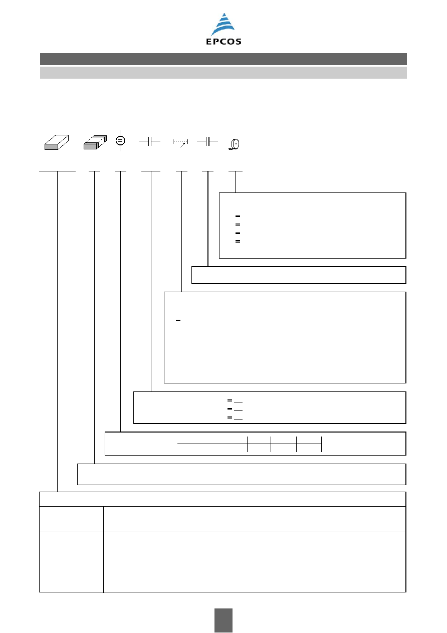
Ordering code system
B37940
A
5
010
C
5
60
Packaging
60
cardboard tape, 180-mm reel
62
blister tape, 180-mm reel
70
cardboard tape, 330-mm reel
72
blister tape, 330-mm reel
^
^
^
^
Decimal place for cap. values <10 pF, otherwise 0
Capacitance tolerance
C
±0.25 pF (standard for capacitance values <10 pF)
^
J
± 5% (standard)
^
C
R
<10 pF:
C
R
≥10 pF:
Capacitance, coded
(example)
010
1 ∑ 10
0
pF =
1 pF
100
10 ∑ 10
0
pF = 10 pF
221
22 ∑ 10
1
pF = 220 pF
^
^
^
Rated voltage
Rated voltage [VDC]
Code
50
100
5
1
Internal coding
Type and size
Chip size
(inch / mm)
0402 / 1005
0603 / 1608
0805 / 2012
1206 / 3216
Temperature characteristic
C0G
B37920
B37930
B37940
B37871
"A" indicates Advanced series
Chip
Advanced series; C0G
Multilayer ceramic capacitors
5
10/06
Please read Cautions and warnings and
Important notes at the end of this document.
Ordering code system
B37941
A
5
102
K
0
60
Packaging
60 cardboard tape, 180-mm reel
62 blister tape, 180-mm reel
70 cardboard tape, 330-mm reel
72 blister tape, 330-mm reel
^
^
^
^
Internal coding
Capacitance tolerance
K
±10% (standard)
^
Capacitance, coded
(example)
102
10 ∑ 10
2
pF =
1 nF
104
10 ∑ 10
4
pF = 100 nF
223
22 ∑ 10
3
pF = 22 nF
^
^
^
Rated voltage
Rated voltage [VDC]
Code
25
50
100
0
5
1
Type and size
Chip size
(inch / mm)
0603 / 1608
0805 / 2012
1206 / 3216
Temperature characteristic
X7R
B37931
B37941
B37872
Internal coding
"A" indicates Advanced series
Chip
Advanced series; X7R
Multilayer ceramic capacitors