
SAW Components
Data Sheet B3559

2
May 09, 2001
SAW Components
B3559
345,00 MHz
Low-loss Filter
Data Sheet
Features
s
RF low-loss filter for remote control receivers
s
Package for Surface Mounted Technology
(SMT)
s
Balanced and unbalanced operation possible
Terminals
s
Ni, gold plated
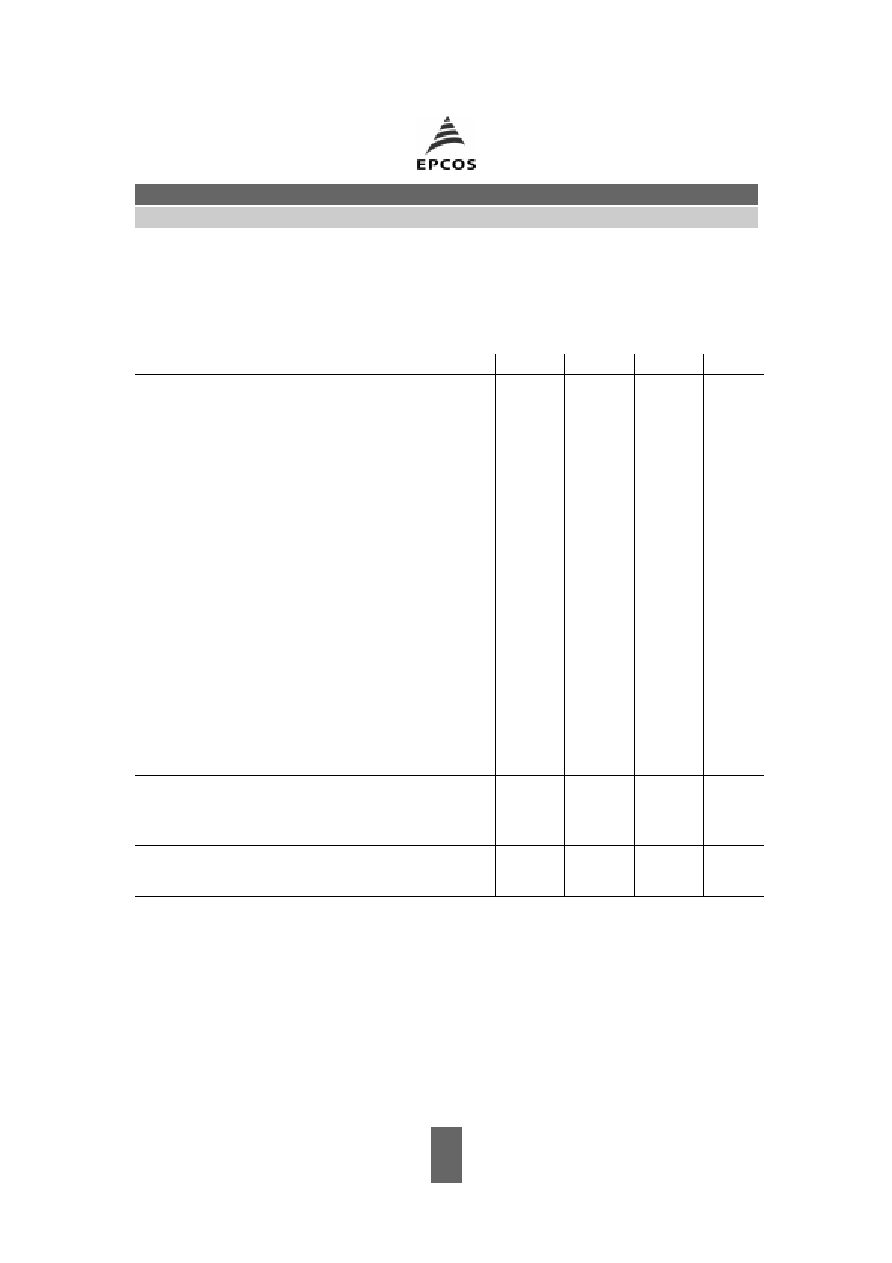
Pin configuration
1
Input Ground
2
Input
5
Output
6
Output Ground
4,8
Case - Ground
3,7
to be grounded
Electrostactic Sensitive Device (ESD)
Type
Ordering code
Marking and package
according to
Packing
according to
B3559
B39351-B3559-U310
C61157-A7-A56
F61074-V8070-Z000
Maximum ratings
Operable temperature range
T
A
�45/+90
�C
Storage temperature range
T
stg
�45/+90
�C
DC voltage
V
DC
0
V
Source power
P
S
0
dBm
source impedance 50
typ. dimensions in mm, approx. weight 0,1 g
Ceramic package QCC8C
3
May 09, 2001
SAW Components
B3559
345,00 MHz
Low-loss Filter
Data Sheet
Characteristics
Reference temperature:
T
A
= 25 �C
Terminating source impedance:
Z
S
= 50
and matching network
Terminating load impedance:
Z
L
= 50
and matching network
1)
Temperature dependence of
f
C
:
f
C
(
T
A
) =
f
C
(
T
0
) (1 +
TC
f
(
T
A
�
T
0
)
2
)
min.
typ.
max.
Center frequency
f
C
--
345,03
--
MHz
(center frequency between 3 dB points)
Minimum insertion attenuation
min
344,90 ... 345,10 MHz
--
2,0
3,0
dB
Pass band (relative to
min
)
344,94 ... 345,13 MHz
--
0,8
2,0
dB
344,90 ... 345,17 MHz
--
1,0
3,0
dB
344,87 ... 345,20 MHz
--
1,5
6,0
dB
Relative attenuation (relative to
min
)
rel
10,00 ... 300,00 MHz
45
50
--
dB
300,00 ... 341,00 MHz
40
45
--
dB
341,00 ... 344,00 MHz
15
20
--
dB
346,10 ... 347,00 MHz
10
15
--
dB
347,00 ... 350,00 MHz
20
25
--
dB
350,00 ... 450,00 MHz
35
40
--
dB
450,00 ... 1000,00 MHz
45
50
--
dB
Impedance for pass band matching
Input:
Z
IN
=
R
IN
||
C
IN
--
350 || 2,80
--
|| pF
Output:
Z
OUT
=
R
OUT
||
C
OUT
--
350 || 2,80
--
|| pF
Temperature coefficient of frequency
1)
TC
f
--
�0,03
--
ppm/K
2
Frequency inversion point
T
0
10
--
30
�
C
4
May 09, 2001
SAW Components
B3559
345,00 MHz
Low-loss Filter
Data Sheet
Characteristics
Reference temperature:
T
A
= �45 ... 90 �C
Terminating source impedance:
Z
S
= 50
and matching network
Terminating load impedance:
Z
L
= 50
and matching network
min.
typ.
max.
Center frequency
f
C
--
345,00
--
MHz
(center frequency between 3 dB points)
Minimum insertion attenuation
min
344,90 ... 345,10 MHz
--
2,0
3,5
dB
Pass band (relative to
min
)
344,94 ... 345,06 MHz
--
0,8
2,0
dB
344,90 ... 345,10 MHz
--
1,0
3,0
dB
344,87 ... 345,13 MHz
--
1,5
6,0
dB
Relative attenuation (relative to
min
)
rel
10,00 ... 300,00 MHz
45
50
--
dB
300,00 ... 341,00 MHz
40
45
--
dB
341,00 ... 343,93 MHz
15
20
--
dB
346,10 ... 347,00 MHz
10
15
--
dB
347,00 ... 350,00 MHz
20
25
--
dB
350,00 ... 450,00 MHz
35
40
--
dB
450,00 ... 1000,00 MHz
45
50
--
dB
Impedance for pass band matching
Input:
Z
IN
=
R
IN
||
C
IN
--
350 || 2,80
--
|| pF
Output:
Z
OUT
=
R
OUT
||
C
OUT
--
350 || 2,80
--
|| pF

5
May 09, 2001
SAW Components
B3559
345,00 MHz
Low-loss Filter
Data Sheet
Matching network to 50
(element values depend on pcb layout and equivalent circuit)
L
s1
= 47 nH
L
s2
= 47 nH
Minimising the crosstalk
For a good ultimate rejection a low crosstalk is necessary. Low crosstalk can be realised with
a good RF layout. The major crosstalk mechanism is caused by the "ground-loop" problem.
Grounding loops are created if input-and output transducer GND are connected on the top-side
of the PCB and fed to the system grounding plane by a common via hole. To avoid the common
ground path, the ground pin of the input- and output transducer are fed to the system ground
plane (bottom PCB plane) by their own via hole. The transducers' grounding pins should be
isolated from the upper grounding plane.
A common GND inductivity of 0.5nH degrades the ultimate rejection (crosstalk) by 20dB.
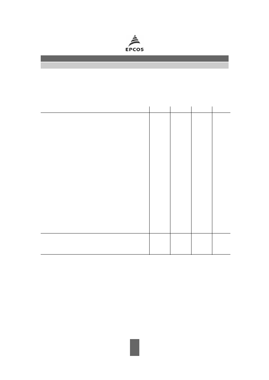
The optimised PCB layout, including matching network for transformation to 50 Ohm, is shown
here. In this PCB layout the grounding loops are minimised to realise good ultimate rejection.
Optimised PCB layout for SAW filters in QCC8C package, pinning 2,5 (top side, scale 1:1)
The bottom side is a copper plane (system ground area). The input and output grounding pins
are isolated and connected to the common ground by separated via holes.
For good contact of the upper grounding area with the lower side it is necessary to place
enough via holes.