
SAW Components
Data Sheet G 3355 K

2
May 08, 2001
SAW Components
G 3355 K
38,90 MHz
IF Filter for Quasi/Split Sound Applications
Data Sheet
Plastic package DIP10K
Standard
s
B/G
Features
s
TV IF filter for quasi/split sound applications
(separate picture and sound channel)
s
Picture channel with Nyquist slope and sound
suppression
s
Group delay predistortion
s
Sound channel with passband only for sound
carriers at 33,40 MHz and 33,05 MHz (NICAM)
s
Suitable for CENELEC EN 55020
Terminals
s
Tinned CuFe alloy
Pin configuration
1
Input
2
Input - ground
3; 8
Chip carrier - ground
4; 5
Output - sound
6; 7
Output - picture
9
Free
10
Not connected
Type
Ordering code
Marking and package
according to
Packing
according to
G 3355 K
B39389-G3355-K100
C61157-A2-A3
F61074-V8068-Z000
Maximum ratings
Operable temperature range
T
A
≠25/+65
∞C
Storage temperature range
T
stg
≠40/+85
∞C
DC voltage
V
DC
12
V
between any terminals
AC voltage
V
pp
10
V
between any terminals
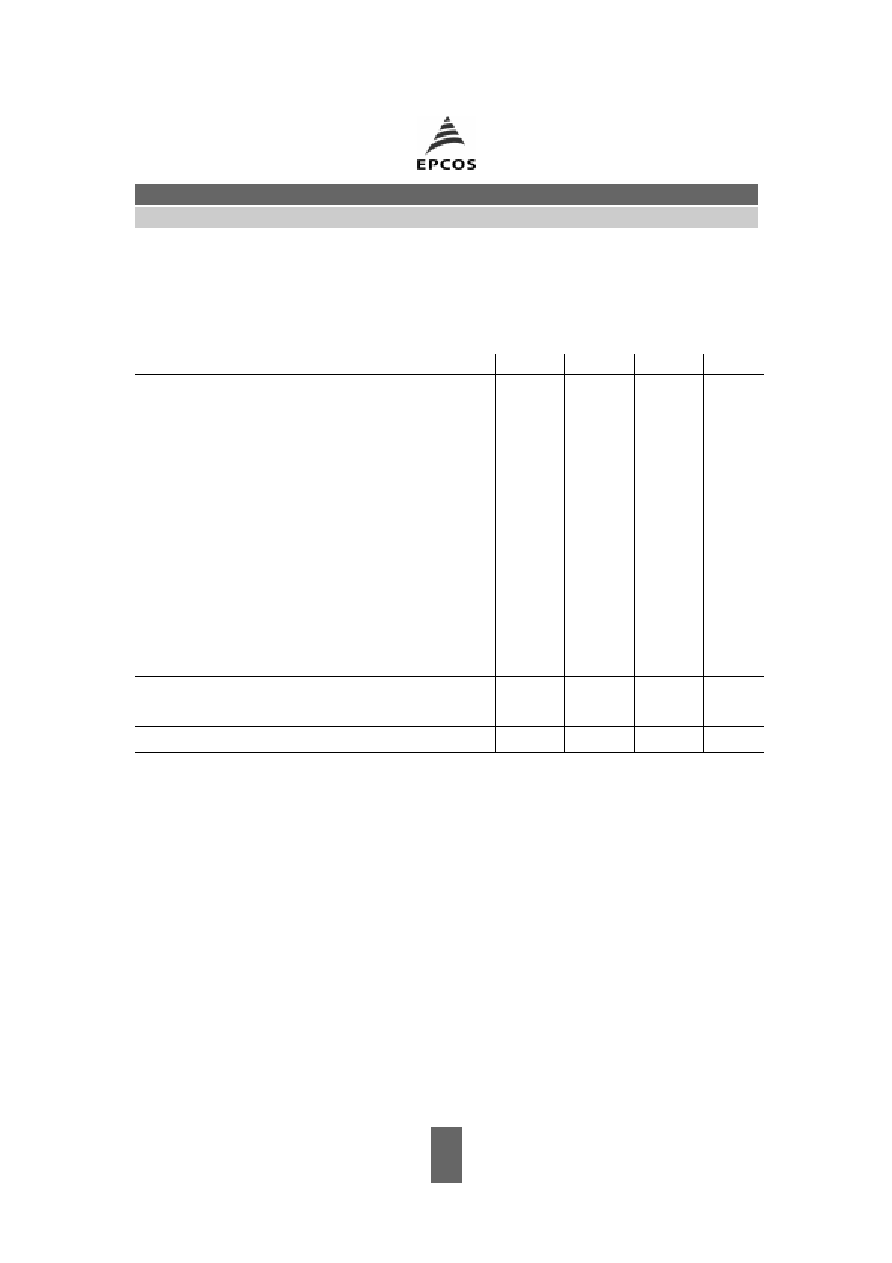
Dimensions in mm, approx. weight 1,8 g

3
May 08, 2001
SAW Components
G 3355 K
38,90 MHz
IF Filter for Quasi/Split Sound Applications
Data Sheet
Characteristics of picture channel
Reference temperature:
T
A
= 25 ∞C
Terminating source impedance:
Z
S
= 50
Terminating load impedance:
Z
L
= 2 k
|| 3 pF
min.
typ.
max.
Insertion attenuation
Reference level for the
37,40 MHz
12,5
14,0
15,5
dB
following data
Relative attenuation
rel
Picture carrier
38,90 MHz
5,0
6,0
7,0
dB
Color carrier
34,47 MHz
≠0,6
0,4
1,4
dB
Sound carrier
33,40 MHz
30,0
48,0
--
dB
Adjacent picture carrier
30,90 MHz
46,0
60,0
--
dB
31,90 MHz
48,0
56,0
--
dB
32,40 MHz
46,0
55,0
--
dB
40,15 MHz
38,0
48,0
--
dB
Adjacent sound carrier
40,40 MHz
46,0
60,0
--
dB
41,40 MHz
45,0
59,0
--
dB
Lower sidelobe
25,00 ... 31,90 MHz
40,0
46,0
--
dB
Upper sidelobe
40,40 ... 45,00 MHz
40,0
46,0
--
dB
Reflected wave signal suppression
1,2
µ
s ... 6,0
µ
s after main pulse
42,0
52,0
--
dB
(test pulse 250 ns,
carrier frequency 37,40 MHz)
Feedthrough signal suppression
1,2
µ
s ... 1,1
µ
s before main pulse
--
56,0
--
dB
(test pulse 250 ns,
carrier frequency 37,40 MHz)
Group delay predistortion
(reference frequency 38,90 MHz)
36,30 MHz
--
≠55
--
ns
34,47 MHz
--
40
--
ns
Impedance at 37,40 MHz
Input:
Z
IN
=
R
IN
||
C
IN
--
1,0 || 24,4
--
k
|| pF
Output:
Z
OUT
=
R
OUT
||
C
OUT
--
1,6 || 3,9
--
k
|| pF
Temperature coefficient of frequency
TC
f
--
≠72
--
ppm/K
4
May 08, 2001
SAW Components
G 3355 K
38,90 MHz
IF Filter for Quasi/Split Sound Applications
Data Sheet
Characteristics of sound channel
Reference temperature:
T
A
= 25 ∞C
Terminating source impedance:
Z
S
= 50
Terminating load impedance:
Z
L
= 2 k
|| 3 pF
min.
typ.
max.
Insertion attenuation
Reference level for the
33,05 MHz
12,7
14,2
15,7
dB
following data
Relative attenuation
rel
Sound carrier
33,40 MHz
1,0
2,0
3,0
dB
Picture carrier
38,90 MHz
42,0
56,0
--
dB
Color carrier
34,47 MHz
28,0
35,0
--
dB
Adjacent picture carrier
30,90 MHz
30,0
37,0
--
dB
31,90 MHz
32,0
41,0
--
dB
Adjacent sound carrier
40,40 MHz
42,0
53,0
--
dB
41,40 MHz
42,0
54,0
--
dB
Lower sidelobe
25,00 ... 31,90 MHz
28,0
34,0
--
dB
Upper sidelobe
38,90 ... 45,00 MHz
38,0
46,0
--
dB
Impedance at 33,05 MHz
Output:
Z
OUT
=
R
OUT
||
C
OUT
--
4,1 || 2,6
--
k
|| pF
Temperature coefficient of frequency
TC
f
--
≠72
--
ppm/K
5
May 08, 2001
SAW Components
G 3355 K
38,90 MHz
IF Filter for Quasi/Split Sound Applications
Data Sheet
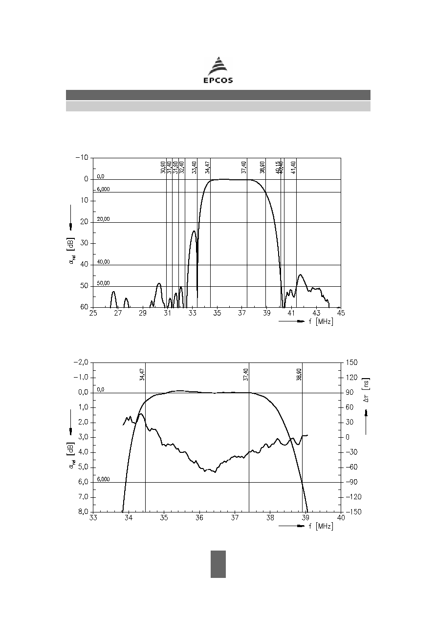
Frequency response of picture channel