
73
10/02
Long-life grade capacitors
Applications
I
General industrial electronics
I
For switch-mode power supplies in
professional equipment
Features
I
High reliability
I
High ripple current capability
I
All-welded construction ensures
reliable electrical contact
I
Version with low-inductance design available
Construction
I
Charge-discharge proof, polar
I
Aluminum case with insulating sleeve
I
Poles with screw terminal connections
I
Mounting with ring clips, clamps or threaded stud
I
The bases of types with threaded stud are not insulated
KAL0567-B
B4345
6 B43458
B41456
Capacitors with Screw Terminals
B41458
Compact
≠
85 ∞C
B41456, B41458
74
10/02
Compact ≠ 85 ∞C
B41456 / B41458
Specifications and characteristics in brief
Ripple current capability
Due to the ripple current capability of the contact elements, the following current upper limits must
not be exceeded:
Rated voltage
U
R
Surge voltage
U
S
16 ... 100 VDC
1,15 ∑
U
R
Rated capacitance
C
R
Capacitance tolerance
2 200 ... 680 000
µF
± 20 % M
Leakage current
I
L
(5 min, 20 ∞C)
Self-inductance
ESL
Approx. 20 nH
Capacitors with low-inductance design:
d
64,3 mm: approx. 13 nH
Useful life
85 ∞C;
U
R
;
I
~
R
40 ∞C;
U
R
; 2,9 ∑
I
~
R
> 12 000 h
> 200 000
h
Requirements:
C
/
C
± 45 % of initial value
ESR
3 times initial specified limit
I
L
initial specified limit
Failure percentage:
1 %
Failure rate:
40 fit ( 40 ∑ 10
≠9
/h)
(for definiton "fit", refer to chapter
"Quality"
, page 62)
Voltage endurance test
85 ∞C;
U
R
2 000 h
Post test requirements:
C
/
C
± 15 % of initial value
ESR
1,3 times initial specified limit
I
L
initial specified limit
Vibration resistance
To IEC 60068-2-6, test Fc:
displacement amplitude 0,75 mm, frequency range 10 to 55 Hz,
acceleration max. 10
g
, duration 3
◊ 2 h
IEC climatic category
To IEC 60068-1:
40/085/56 (≠ 40 ∞C/+ 85 ∞C/56 days damp heat test)
Detail specification
Sectional specification
Similar to CECC 30301-810
IEC 60384-4
Capacitor diameter
51,6 mm
64,3 mm
76,9 mm
I
~
max
30 A
40 A
50 A
I
L
0,3
µA
C
R
µF
-------
U
R
V
-------
Ë
¯
Ê
ˆ
0,7
4
µA
+
75
10/02
Compact ≠ 85 ∞C
B41456 / B41458
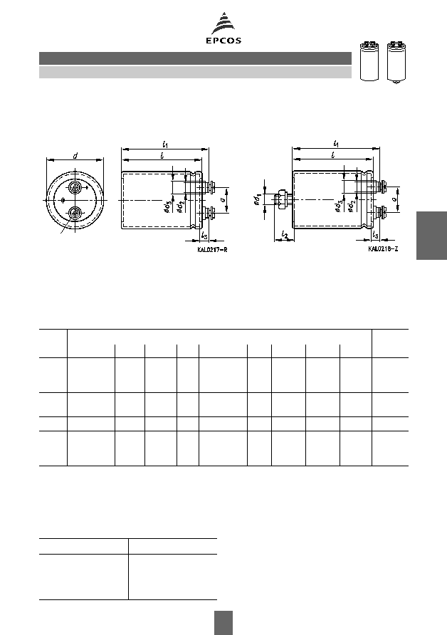
Dimensional drawings
Type B41456
Type B41458
Ring clip/clamp mounting
Threaded stud mounting
Positive pole marking:
+
Screw terminals with UNF threads are available upon request.
Dimensions and weights
Dimensions are also valid for low-inductance design.
Packing
For ecological reasons the packing is pure cardboard.
Ter-
minal
Dimensions (mm) with insulating sleeve
Approx.
wt. (g)
d
I
± 1
I
1
± 1
I
2
+ 0
l
3
d
1
d
2
max
d
3
max
a
+ 0,2
≠ 1
≠ 0,4
M 5
M 5
M 5
35,7
+ 0/≠ 0,8
35,7
+ 0/≠ 0,8
35,7
+ 0/≠ 0,8
55,7
80,7
105,7
62,2
87,2
112,2
13
13
13
7,0
+ 0,2/≠ 1
7,0
+ 0,2/≠ 1
7,0
+ 0,2/≠ 1
M 8
M 8
M 8
8,2
8,2
8,2
13,5
13,5
13,5
12,7
12,7
12,7
65
105
135
M 5
M 5
51,6
+ 0/≠ 0,8
51,6
+ 0/≠ 0,8
80,7
105,7
87,2
112,2
17
17
7,0
+ 0,2/≠ 1
7,0
+ 0,2/≠ 1
M 12
M 12
8,2
8,2
13,5
13,5
22,2
22,2
220
280
M 5
64,3
+ 0/≠ 0,8
105,7
112,2
17
7,0
+ 0,2/≠ 1
M 12 8,2
13,5
28,5
440
M 6
M 6
M 6
76,9
+ 0/≠ 0,7
76,9
+ 0/≠ 0,7
76,9
+ 0/≠ 0,7
105,7
143,2
220,7
111,5
149,0
226,5
17
17
17
6,4
+ 1,1/≠ 0,8
6,4
+ 1,1/≠ 0,8
6,4
+ 1,1/≠ 0,8
M 12
M 12
M 12
17,7
17,7
17,7
17,7
17,7
17,7
31,7
31,7
31,7
540
840
1300
Capacitor diameter
d
Packing units (pieces)
35,7 mm
51,6 mm
64,3 mm
76,9 mm
36
22
15
12
M5: min. reach of screw = 8 mm
M6: min. reach of screw = 12 mm*)
*) 8 mm for low-inductance design

76
10/02
Compact ≠ 85 ∞C
B41456 / B41458
Special designs
I
Low-inductance design
Ordering code:
Accessories
The following items are included in the delivery package, but are not fastened to the capacitors:
The following must be ordered separately:
Ring clips
B44030 (cf. page 169)
Clamps for capacitors with
d
64,3 mm
B44030 (cf. page 173)
Insulating parts
B44020 (cf. page 166)
Design
Identification in 3rd
block of ordering code
Remark
Low inductance (13 nH)
M003
For capacitors with diameter
d
64,3 mm
Thread
Toothed
washers
Screws/Nuts
Maximum
torque
For terminals
M 5
A 5,1 DIN 6797
Cylinder-head screw M 5
◊ 8 DIN 84-4.8
2
Nm
M 6
A 6,4 DIN 6797
Cylinder-head screw M 6
◊ 12 DIN 85-4.8 2,5 Nm
For mounting
M 8
J 8,2 DIN 6797
Hex nut BM 8 DIN 439
4
Nm
M 12
J 12,5 DIN 6797 Hex nut BM 12 DIN 439
10
Nm
77
10/02
Compact ≠ 85 ∞C
B41456 / B41458
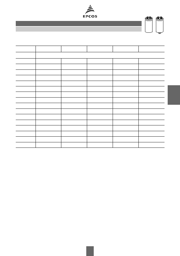
Overview of available types
The capacitance and voltage ratings listed above are available in different cases upon request.
Other voltage and capacitance ratings are also available upon request.
U
R
(VDC)
16
25
40
63
100
C
R
(
µF)
Case dimensions
d
◊
l
(mm)
2 200
35,7
◊ 55,7
3 300
35,7
◊ 80,7
4 700
35,7
◊ 55,7
35,7
◊ 80,7
6 800
35,7
◊ 55,7
35,7
◊ 105,7
10 000
35,7
◊ 55,7
35,7
◊ 80,7
51,6
◊ 80,7
15 000
35,7
◊ 80,7
35,7
◊ 105,7
51,6
◊ 105,7
22 000
35,7
◊ 55,7
35,7
◊ 55,7
35,7
◊ 80,7
51,6
◊ 80,7
64,3
◊ 105,7
33 000
35,7
◊ 55,7
35,7
◊ 80,7
35,7
◊ 105,7
51,6
◊ 105,7
76,9
◊ 105,7
47 000
35,7
◊ 80,7
35,7
◊ 105,7
51,6
◊ 80,7
64,3
◊ 105,7
76,9
◊ 143,2
68 000
35,7
◊ 105,7
51,6
◊ 80,7
51,6
◊ 105,7
76,9
◊ 105,7
100 000
51,6
◊ 80,7
51,6
◊ 105,7
64,3
◊ 105,7
76,9
◊ 143,2
150 000
51,6
◊ 80,7
64,3
◊ 105,7
76,9
◊ 105,7
76,9
◊ 220,7
220 000
64,3
◊ 105,7
64,3
◊ 105,7
76,9
◊ 143,2
330 000
64,3
◊ 105,7
76,9
◊ 143,2
470 000
76,9
◊ 143,2
76,9
◊ 220,7
680 000
76,9
◊ 143,2