Document Outline
- Deckblatt_large_size_607.pdf

Aluminum electrolytic capacitors
For automotive applications,
large size,150 ∞C / 2000 h
Series/Type:
B41607
Date: July 2005
© EPCOS AG 2005. Reproduction, publication and dissemination of this data sheet, enclosures hereto and the
information contained therein without EPCOS' prior express consent is prohibited.

1
EPCOS AG
Please read the important notes, cautions and warnings.
Large size
Aluminum electrolytic capacitors
Introduction
The B41605 and B41607 series were
designed for applications with strin-
gent demands for power and current
carrying capacity at ambient temper-
atures ranging up to 150 ∞C. Tinned
copper leads of 1.2 mm diameter, al-
so allowing determination of the poles
because of the different lead length,
can be either welded or soldered.
To stand up the specified vibrational
stability in an automobile, EPCOS
developed a special process for these
models, in the meantime patented,
that fixes the capacitor winding so re-
liably by a sophisticated corrugation
configuration that vibrational stability
up to 40 g can be specified even for
these large-sized models.
40 g corrugation profile
Aluminum case
Winding
KAL0982-9-E
Insulating sleeve
Up to 40 g vibration stability version
Snap-in version
Up to 40 g vibration stability thanks to rugged corrugation
07/05
2
EPCOS AG
Please read the important notes, cautions and warnings.
Data sheet
B41607
Specifications and characteristics in brief
Product
Rated voltage V
R
25 ... 63 VDC
Surge voltage V
surge
1.15 ∑ V
R
Rated capacitance C
R
800 ... 4700 µF
Capacitance tolerance
±20% ; M
Leakage current I
leak
(5 min, 20 ∞C)
Self-inductance ESL
15 nH
Useful life
Requirements:
150 ∞C; V
R
; 0.5 ∑ I~
R
>
2 000 h
C/C
±30% of initial value
125 ∞C; V
R
; I~
R
> 10 000 h
ESR
3 times initial specified limit
85 ∞C; V
R
; 2.1 ∑ I~
R
> 30 000 h
I
leak
initial specified limit
40 ∞C; V
R
; 2.1 ∑ I~
R
> 500 000 h
Voltage endurance test
Post test requirements:
125 ∞C; V
R
5 000 h
C/C
±10% of initial value
ESR
1.3 times initial specified limit
I
leak
initial specified limit
Vibration resistance
To IEC 60068-2-6, test Fc:
40 g vibration stability version
Snap-in version with 3 terminals
displacement amplitude 3 mm,
displacement amplitude 0.75 mm,
frequency range at 10 Hz ... 2 kHz,
frequency range at 10 Hz ... 2 kHz,
acceleration max. 40 g, duration 3 x 2 h
acceleration max. 10 g, duration 3 x 2 h
IEC climatic category
To IEC 60068-1:
55/125/56 (≠ 55 ∞C/+125 ∞C/56 days damp heat test)
Detail specification
Similar to CECC 30301-809
Sectional specification
IEC 60384-4
I
leak
0.006 ∑ µA
C
R
∑
V
R
+ 4 µA
µF V
Specifications and characteristics in brief
Features
s
High reliability and long useful life, up to 2000 h at 150 ∞C
s
High ripple current capability optimized for high frequencies
s
Vibration resistance up to 40 g
s
Shelf life of the capacitor up to 15 years at storage temperatures up to 40 ∞C. To ensure solderability,
the capacitors should be built into the application within one year of delivery. After a total of two years'
storage, the operating voltage must be applied for one hour to ensure the specified leakage current.
s
Variable pin configurations
≠ Up to 40 g vibration stability version with wired terminals.
Weldable and solderable terminals. Tinned copper leads (
1.2 mm).
≠ Snap-in with 3 terminals, protection against polarity reversal.
s
Without insulation sleeve upon request
07/05
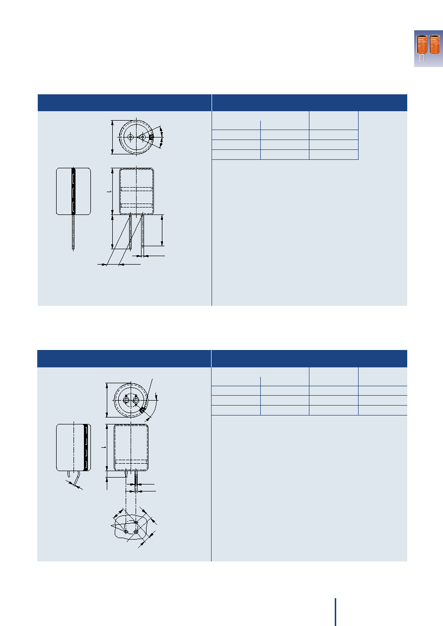
Dimensions (mm)
Approx. weight
Paking units
d +1
l ± 2
(g)
(pieces)
22
40
21
160
25
40
28
130
25
50
35
130
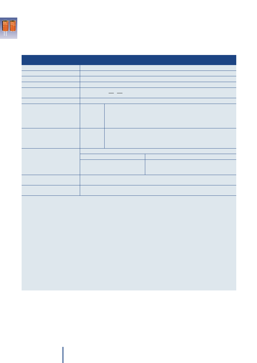
Dimensions (mm)
Approx. weight
d +1
l ± 2
(g)
22
40
21
25
40
28
25
50
35
3
EPCOS AG
Please read the important notes, cautions and warnings.
Data sheet
B41607
Dimensional drawing
Dimensions, weights and packing units
Large size capacitor, snap-in version with 3 terminals
Dimensional drawing
Dimensions and weights
Large size capacitor, up to 40 g vibration stability version with wired terminals
KAL0963-3-E
4
1
∞±
2
5
∞
d
0.8
1.5±0.2
Minus pole marking
¯2±0.1
3.
3±
0.
1
10
±0
.1
4.7
5±
0.1
¯2.5 min.
Mounting holes
1
4.5
_
+0.2
0.1
0.8
_
25
2
_
KAL0962-U-E
8.4±0.5
+0.04
¯1.2
0.02
_
2
23
_
positions for minus
Permissible range of
pole marking
d
)
25
∞
)
)
2
5
∞
Packing units on request.
07/05

25
2500
22 x 40
22
32
115
22
22
10.7
5.6
2.8
B41607A5258M***
3300
25 x 40
16
22
80
15
15
14.5
7.6
3.8
B41607A5338M***
4700
25 x 50
12
17
60
11
11
18.5
9.7
4.9
B41607A5478M***
40
1500
22 x 40
31
42
115
22
21
10.5
5.5
2.8
B41607A7158M***
2000
25 x 40
19
27
80
14
14
14.6
7.7
3.8
B41607A7208M***
2700
25 x 50
15
21
60
11
11
18.5
9.7
4.9
B41607A7278M***
55
1100
22 x 40
35
49
115
22
21
10.5
5.5
2.8
B41607A0118M***
1500
25 x 40
22
32
80
14
14
14.6
7.7
3.8
B41607A0158M***
2000
25 x 50
17
24
60
11
11
18.5
9.8
4.9
B41607A0208M***
63
800
22 x 40
40
56
115
22
22
10.3
5.4
2.7
B41607A8807M***
1100
25 x 40
27
38
90
14
14
14.5
7.6
3.8
B41607A8118M***
1500
25 x 50
20
28
65
11
11
18.5
9.7
4.9
B41607A8158M***
4
EPCOS AG
Please read the important notes, cautions and warnings.
Data sheet
B41607
Technical data, case dimensions and ordering codes
V
R
C
R
Case
ESR
typ
ESR
max
ESR
max
ESR
max
Z
max
I~
max
I~
R
I~
max
Ordering code
100 Hz
dimensions 100 Hz
100 Hz
100 Hz
10 kHz
100 kHz 10 kHz
10 kHz
10 kHz
20 ∞C
d x l
20 ∞C
20 ∞C
≠40 ∞C
20 ∞C
20 ∞C
105 ∞C
125 ∞C
150 ∞C
VDC
µF
mm
m
m
m
m
m
A
A
A
*** = "002" for snap-in version with 3 terminals (protection against polarity reversal), fully insulated.
"009" for up to 40 g vibration stability version with wired terminals, fully insulated.
07/05
5
EPCOS AG
Please read the important notes, cautions and warnings.
Data sheet
B41607
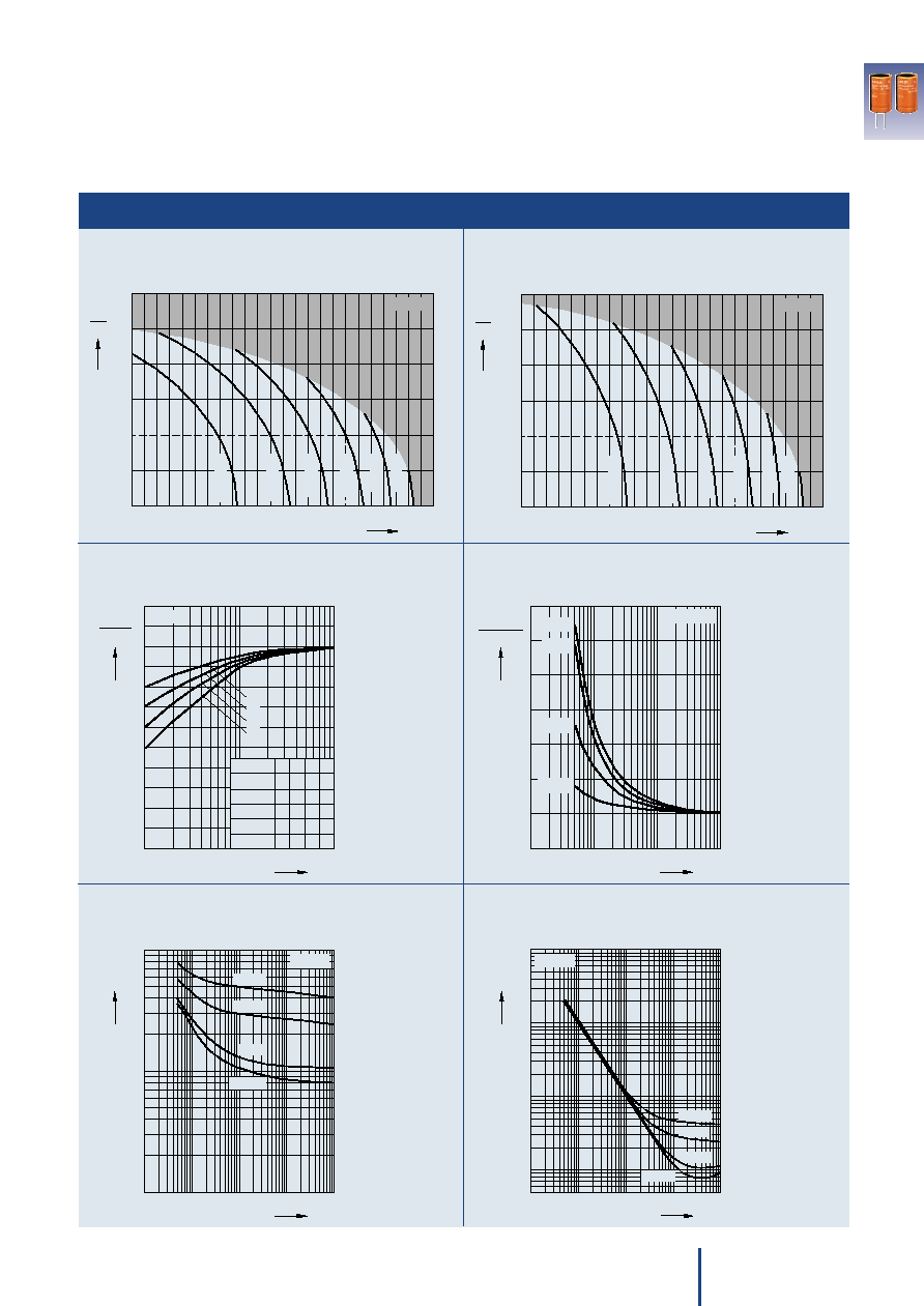
Characteristics
100
1.0
40
0
0.5
50
60
80
500 000 h
70
100 000 h
90
~
~
1.5
2.0
2.5
R
3.0
4 000 h
140
120
30 000 h
110
10 000 h
130
A
T
∞C
2 000 h
160
KAL0954-4
B41607
100
1.0
40
0
0.5
50
60
80
500 000 h
70
100 000 h
90
~
~
1.5
2.0
2.5
R
3.0
4 000 h
140
120
30 000 h
110
10 000 h
130
C
T
∞C
2 000 h
160
B41607
KAL0955-C
10
f
KAL0956-K
0
B41607
2
5
10
3
Hz 10
4
0.1
0.2
0.3
0.4
0.5
0.6
0.7
0.8
0.9
1.2
~
10 kHz
f
~
¯ [mm]
30 35
R
V
40 VDC
55 VDC
b a
c b
25 VDC
a a
c
d
b
a
5
63 VDC
c c
25
b
c
d
d
22
a
b
c
c
10
1
f
KAL0835-R
0
1
2
3
4
5
7
5 10
2
5 10
3
10
Hz
4
85 ∞C
20 ∞C
40 ∞C
_
125 ∞C
B41607
ESR
10 kHz
ESR
f
10
1
10
2
5
3
10
10
4
10
5
5
5
Hz
f
KAL0834-I
10
3
_
ESR
10
_
2
_
40 ∞C
_
25 ∞C
20 ∞C
_
> 60 ∞C
5
B41607
10
1
_
10
1
10
2
5
3
10
10
4
10
5
5
5
Hz
f
KAL0833-A
Z
10
2
_
10
1
40 ∞C
_
20 ∞C
_
> 60 ∞C
25 ∞C
_
B41607
10
_
1
10
0
5
5
5
Frequency factor of permissible ripple current I~
versus frequency f
Frequency characteristics of ESR
versus frequency f at different temperatures T
Typical behavior
Impedance Z
versus frequency f at different temperatures
Typical behavior for 1500 µF/55 V
Equivalent series resistance ESR
versus frequency f at different temperatures
Typical behavior for 1500 µF/55 V
Useful life
depending on ambient temperature T
A
under ripple
current operating conditions at V
R
Useful life
depending on case temperature T
C
under ripple
current operating conditions at V
R
07/05

6
EPCOS AG
Important notes
The following applies to all products
named in this publication:
1. Some parts of this publication
contain statements about the
suitability of our products for
certain areas of application.
These statements are based on
our knowledge of typical require-
ments that are often placed on
our products in the areas of appli-
cation concerned. We never-
theless expressly point out that
such statements cannot be re-
garded as binding statements
about the suitability of our
products for a particular cus-
tomer application. As a rule,
EPCOS is either unfamiliar with
individual customer applications
or less familiar with them than the
customers themselves. For these
reasons, it is always ultimately
incumbent on the customer to
check and decide whether an
EPCOS product with the proper-
ties described in the product
specification is suitable for use in
a particular customer application.
2. We also point out that in individ-
ual cases, a malfunction of
passive electronic compo-
nents or failure before the end
of their usual service life can-
not be completely ruled out in
the current state of the art,
even if they are operated as
specified. In customer applica-
tions requiring a very high level of
operational safety and especially
in customer applications in which
the malfunction or failure of a pas-
sive electronic component could
endanger human life or health
(e.g. in accident prevention or life-
saving systems), it must therefore
be ensured by means of suitable
design of the customer applica-
tion or other action taken by the
customer (e.g. installation of pro-
tective circuitry or redundancy)
that no injury or damage is sus-
tained by third parties in the event
of malfunction or failure of a pas-
sive electronic component.
3. The warnings, cautions and
product-specific notes must
be observed.
4. In order to satisfy certain technical
requirements, some of the
products described in this
publication may contain sub-
stances subject to restrictions
in certain jurisdictions (e.g.
because they are classed as
"hazardous"). Useful information
on this will be found in our Materi-
al Data Sheets on the Internet
(www.epcos.com/material).
Should you have any more de-
tailed questions, please contact
our sales offices.
5. We constantly strive to improve
our products. Consequently, the
products described in this
publication may change from
time to time. The same is true of
the corresponding product speci-
fications. Please check therefore
to what extent product descrip-
tions and specifications contained
in this publication are still applica-
ble before or when you place an
order.
We also reserve the right to
discontinue production and
delivery of products. Conse-
quently, we cannot guarantee that
all products named in this publi-
cation will always be available.
6. Unless otherwise agreed in indi-
vidual contracts, all orders are
subject to the current version
of the "General Terms of De-
livery for Products and Ser-
vices in the Electrical Indus-
try" published by the German
Electrical and Electronics In-
dustry Association (ZVEI).
7. The trade names EPCOS,
CeraDiode, CSSP, SIMID,
PhaseCap, PhaseMod, SIFI,
SIKOREL, SilverCap, SIOV,
SIP5D, SIP5K, TOPcap,
UltraCap, WindCap are trade-
marks registered or pending in
Europe and in other countries.
Further information will be found
on the Internet at
www.epcos.com/trademarks.
07/05

7
EPCOS AG
Cautions and warnings
The electrolytes used by EPCOS have not only been optimized with a view to the intended application, but also
with regard to health and environmental compatibility. They do not contain any solvents that are detrimental to
health, e.g. dimethyl formamide (DMF) or dimethyl acetamide (DMAC).
Furthermore, part of the high-voltage electrolytes used by EPCOS are self-extinguishing. They contain flame-
retarding substances which will quickly extinguish any flame that may have been ignited.
As far as possible, EPCOS does not use any dangerous chemicals or compounds to produce operating elec-
trolytes. However, in exceptional cases, such materials must be used in order to achieve specific physical and
electrical properties because no safe substitute materials are currently known. However, the amount of danger-
ous materials used in our products has been limited to an absolute minimum. Nevertheless, the following rules
should be observed when handling Al electrolytic capacitors:
s
Any escaping electrolyte should not come into contact with eyes or skin.
s
If electrolyte does come into contact with the skin, wash the affected parts immediately with running water.
If the eyes are affected, rinse them for 10 minutes with plenty of water. If symptoms persist, seek medical treat-
ment.
s
Avoid breathing in electrolyte vapor or mists. Workplaces and other affected areas should be well ventilated.
Clothing that has been contaminated by electrolyte must be changed and rinsed in water.
Personal safety
s
Make sure that polar capacitors are connected with the right polarity.
s
Voltages polarity clashes should be prevented by connecting a diode.
s
Do not damage the insulating sleeve, especially when ring clips are used for mounting.
s
Do not exceed the upper category temperature (UCT).
s
Make periodic inspections of the capacitors. Before the inspection, make sure that the power supply
is turned off and carefully discharge the electricity of the capacitors.
s
Do not apply any mechanical stress to the capacitor terminals.
s
The internal structure of single-ended capacitors may be damaged if excessive force is applied to
the lead wires.
s
Avoid any compressive, tensile or flexural stress.
s
Do not move the capacitor after soldering to the PC board.
s
Do not pick up the PC board by the soldered capacitor.
s
Do not insert the capacitor on the PC board with a hole space different to the lead space specified.
s
Do not exceed the specified time or temperature limits during soldering.
s
Capacitors should be dipped in solder for less than 10 seconds.
s
Do not allow halogenated hydrocarbons to come into contact with aluminum electrolytic capacitors.
s
Avoid external energy, such as fire or electricity.
s
Avoid overload of the capacitors.
Product safety
Failure to follow cautions and warnings may result in the worst case in premature failure, bursting and fire.
07/05

8
EPCOS AG
Product safety
Polarity
Make sure that polar capacitors are
connected with the right polarity. If
the opposite polarity were to be ap-
plied, this would cause an electrolyt-
ic process resulting in the formation
of a dielectric layer on the cathode
foil. In this case strong internal heat
generation and gas emission may
occur and destroy the capacitor.
Polar capacitors do not tolerate a
voltage reversal. Incorrect polarities
of up to 1.5 V are, however, permis-
sible for short periods of time as the
formation of a damaging oxide layer
on the cathode only starts at volt-
ages of this magnitude.
Reverse voltage
Aluminum electrolytic capacitors are
polar capacitors. Where necessary,
voltages of opposite polarity should
be prevented by connecting a
diode. The diode's conducting-state
voltage of approximately 0.8 V is
permissible. Reverse voltages
1.5 V
are tolerable for a duration of less
than 1 second, but not in continu-
ous or repetitive operation.
Breakdown strength of
insulating sleeves
The minimum breakdown strength of
the insulating sleeve is 2500 VAC or
3500 VDC. A test method for verifying
the breakdown strength of the slee-
ves is described in IEC 60384-4.
In order to ensure full breakdown
strength, care must be taken not to
damage the insulating sleeve, espe-
cially when ring clips are used for
mounting. The insulation can be im-
proved by using an insulating strip.
In such cases, attention must be
paid to any relevant regulations
(e.g. VDE, BSA or UL regulations).
Upper category tempera-
ture (UCT)
The upper category temperature is
the maximum permissible ambient
temperature at which a capacitor
may be continuously operated. If
this limit is exceeded, the capacitor
may fail prematurely.
For some type series, however, op-
eration at temperatures above the
UCT is permissible for short periods
of time. The maximum permissible
operating temperatures are specified
in the data sheets for the individual
type series under "Specifications
and characteristics in brief", section
"Useful life".
Maintenance
Make periodic inspections for the
capacitors that have been used in
the devices for industrial applica-
tions. Before the inspection, make
that the power supply is turned off
and carefully discharge the electricity
of the capacitors. To check the
capacitors, make sure of the polarity
when measuring the capacitors by
using a volt-ohm meter, for instance.
Also, do not apply any mechanical
stress to the capacitor terminals.
The following items should be
checked by the periodic inspections.
Significant damage to appearances:
venting, electrolyte leakage, etc.
Electrical characteristics: leakage
current, capacitance, tan
and other
characteristics prescribed in the
catalogs or product specifications.
If any of the above is found, replace
it or take any other proper measure.
Halogenated hydrocarbons may
cause serious damage if allowed to
come into contact with aluminum
electrolytic capacitors.
Mounting position
An overpressure vent ensures that
the gas can escape when the pres-
sure reaches a certain level.
To prevent electrolyte from leaking
out when the gas is "vented", the
capacitor should be mounted in an
upright position (90∞). All of these
mounting positions are intended to
avoid a vent-down installation of the
capacitor.
Mounting of single-ended
capacitors
For further information see page 67.
Soldering
Excessive time or temperature dur-
ing soldering will affect capacitor's
characteristics and cause damage
to the insulation sleeve. Capacitors
should be dipped in solder for less
than 10 seconds. Contact of the
sleeve with soldering iron must be
avoided.
Soldering, cleaning agents
Halogenated hydrocarbons may
cause serious damage if allowed to
come into contact with aluminum
electrolytic capacitors. These sol-
vents may dissolve or decompose
the insulating film and reduce the in-
sulating properties to below the per-
missible level. The capacitor seals
may be affected and swell, and the
solvents may even penetrate them.
This will lead to premature compo-
nent failure.
Because of this, measures must be
taken to prevent electrolytic capaci-
tors from coming into contact with
the solvents when using halogenat-
ed hydrocarbon solvents to clean
printed circuit boards after soldering
the components, or to remove flux
residues. If it is not possible to pre-
vent the electrolytic capacitors from
being wetted by the solvent, halo-
gen-free solvents must be used in
order to eliminate the possibility of
damage.
Passive flammability
Under the influence of high external
energy, such as fire or electricity, the
flammable parts may get inflamed.
Clause 38 of the relevant specifica-
tion CECC 30000 (Harmonized
System of Quality Assessment for
Electronic Components; Generic
Specification: Fixed Capacitors)
refers to IEC Publication 695-2-2
(Needle Flame Test) for testing the
passive flammability of capacitors.
And in CECC 30000, severities and
requirements for different categories
of flammability are listed. Most of
aluminum electrolytic capacitors
meet the requirements of category C.
Active flammability
In rare cases the component may
ignite caused by heavy overload or
some capacitor defect. One reason
could be the following: During the
operation of an aluminum electrolytic
capacitor with nonsolid electrolyte,
there is a small quantity of hydrogen
developed in the component. Under
normal conditions, this gas perme-
ates easily out of the capacitor. But
under exceptional circumstances,
higher gas amounts may develop
and may catch fire if a sparking
would occur at the same time.
As explained above a fire risk can't
be totally excluded. Therefore, it is
recommended to use special mea-
sures in critical applications (e.g. ad-
ditional encapsulation of the equip-
ment for mining applications).
07/05