Aluminum Electrolytic Capacitors B41754
110
10/02
SIKOREL
®
125
Long-life grade capacitors
Applications
I
High-reliability equipment in automotive power
electronics, e.g. integrated starter alternator
I
Applications with highest ripple current load at high frequencies
Features
I
Outstanding ripple current capability
I
Optimized for high frequencies
I
Optimized design for bottom cooling
I
Low profile
I
Vibration resistance 30
g
upon request
I
Stud mounting upon request
I
Shelf life up to 10 years
I
All-welded construction ensures reliable electrical contact
Construction
I
Charge-discharge proof, polar
I
Aluminum case without insulating sleeve
(for bottom cooling)
I
Poles with screw terminal connections
I
Mounting with ring clips or clamps
KAL0574-T
B41754
Capacitors with Screw Terminals
Automotive
125 °C
B41754
111
10/02
B41754
Automotive
125 °C
Specifications and characteristics in brief
Ripple current capability
Due to the ripple current capability of the contact elements, the following current upper limits must
not be exceeded:
I
~
max
= 50 A
In case of additional thermal cooling:
I
~
max
= 55 A
Rated voltage
U
R
Surge voltage
U
S
25 ... 63 VDC
1,15 ·
U
R
Rated capacitance
C
R
Capacitance tolerance
3 900 to 20 000
µF
± 20 % M
Leakage current
I
L
(5 min, 20 °C)
Self-inductance
ESL
Approx. 13 nH
Useful life
125 °C,
U
R
;
I
~
R
85 °C,
U
R
;
I
~
max
40 °C,
U
R
; 3,4 ·
I
~
R
> 2 500 h
> 15 000 h
>200 000 h
Requirements:
C
/
C
± 45 % of initial value
ESR
3 times initial specified limit
I
L
initial specified limit
Failure percentage:
1 %
Failure rate:
20 fit ( 20 · 10
9
/h)
(for definiton "fit", refer to chapter
"Quality"
, page 62)
Voltage endurance test
125 °C;
U
R
;
I
~
R
2 000 h
Post test requirements:
C
/
C
± 15 % of initial value
ESR
1,3 times initial specified limit
I
L
initial specified limit
Vibration resistance
To IEC 60068-2-6, test Fc:
displacement amplitude 0,75 mm, frequency range 10 to 55 Hz,
acceleration max. 10
g
, duration 3
× 2 h
Vibration resistance up to 30
g
upon request
IEC climatic category
To IEC 60068-1:
55/125/56 ( 55 °C/+ 125 °C/56 days damp heat test)
Detail specifications
Sectional specification
Similar to CECC 30301-803, CECC 30301-807
IEC 60384-4
I
L
0,3
µA
C
R
µF
-------
U
R
V
-------
è
ø
æ
ö
0,7
4
µA
+
112
10/02
B41754
Automotive
125 °C
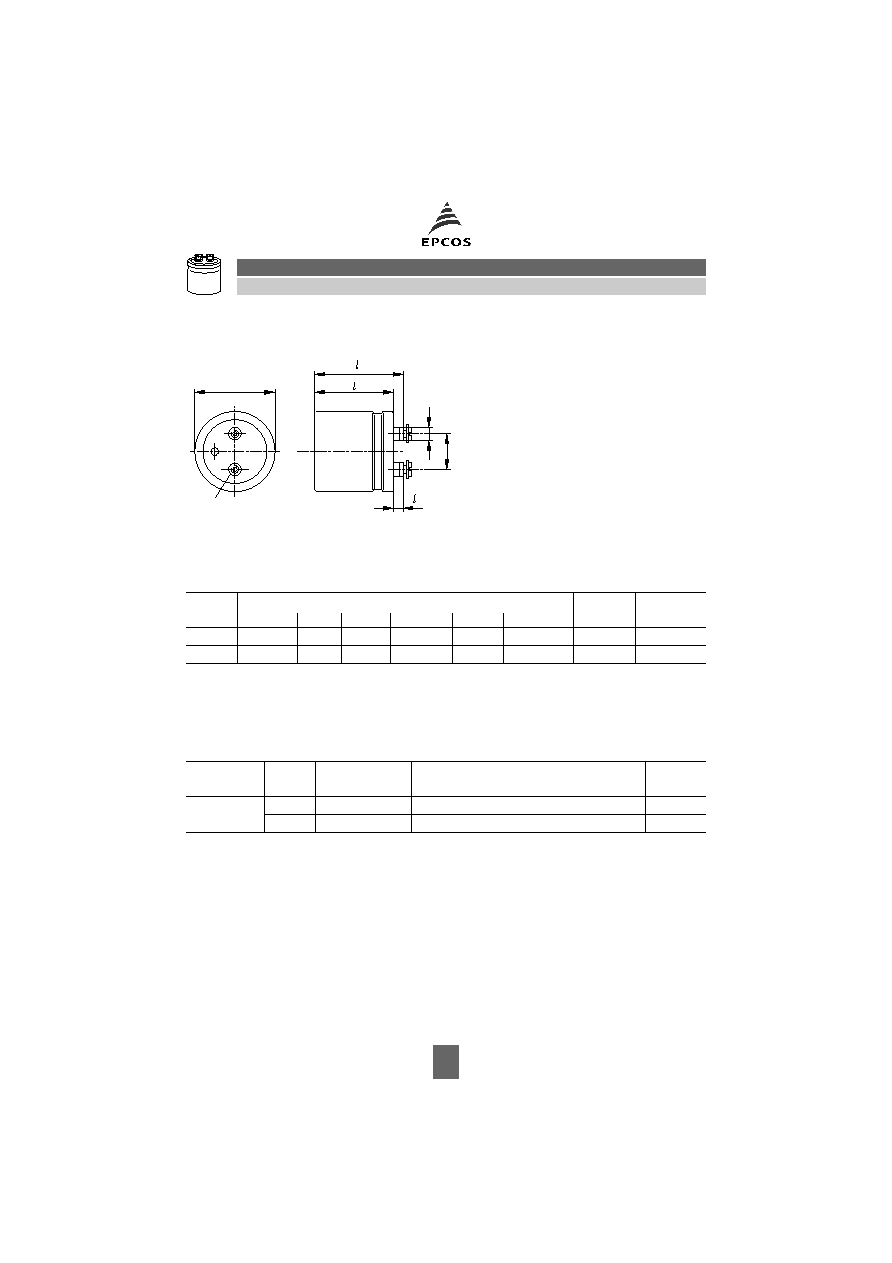
Dimensional drawing
Dimensions, weights and packing units
For ecological reasons the packing is pure cardboard.
Accessories
The following items are included in the delivery package, but are not fastened to the capacitors:
The following must be ordered separately:
Ring clips
B44030 (cf. page 169)
Insulating parts
B44020 (cf. page 166)
Terminal Dimensions (mm)
Approx.
weight (g)
Packing unit
pieces
d
+0/0,4
I
± 0,8
I
1
± 0,8
l
3
+0,2/1
d
2
± 0,2
a
+0,2/0,4
M 5
50,9
39,5
46,1
7,0
8,2
22,2
115
22
M 5
50,9
49,5
56,1
7,0
8,2
22,2
135
22
Thread
Toothed
washers
Screws/Nuts
Maximum
torque
For terminals
M 5
A 5,1 DIN 6797
Cylinder-head screw M 5
× 8 DIN 84-4.8
2 Nm
M 6
A 6,4 DIN 6797
Cylinder-head screw M 6
× 12 DIN 85-4.8 2,5 Nm
KAL0824-B-E
+
d
M5: Min. reach of screw = 8 mm
a
Positive pole marking: +
1
3
2
ø
d
Stud mounting upon request
113
10/02
B41754
Automotive
125 °C
Overview of available types
Case dimensions and ordering codes
U
R
(VDC)
25
40
55
63
C
R
(
µF)
Case dimensions
d
×
l
(mm)
3 900
50,9
× 39,5
4 700
50,9
× 39,5
6 000
50,9
× 49,5
7 500
50,9
× 39,5
50,9
× 49,5
12 000
50,9
× 39,5
50,9
× 49,5
20 000
50,9
× 49,5
U
R
VDC
C
R
µF
Case dimensions
d
×
l
mm
Ordering code
25
12 000
50,9
× 39,5
B41754A5129M000
20 000
50,9
× 49,5
B41754A5209M000
40
7 500
50,9
× 39,5
B41754A7758M000
12 000
50,9
× 49,5
B41754A7129M000
55
4 700
50,9
× 39,5
B41754A0478M000
7 500
50,9
× 49,5
B41754A0758M000
63
3 900
50,9
× 39,5
B41754A8398M000
6 000
50,9
× 49,5
B41754A8608M000
114
10/02
B41754
Automotive
125 °C
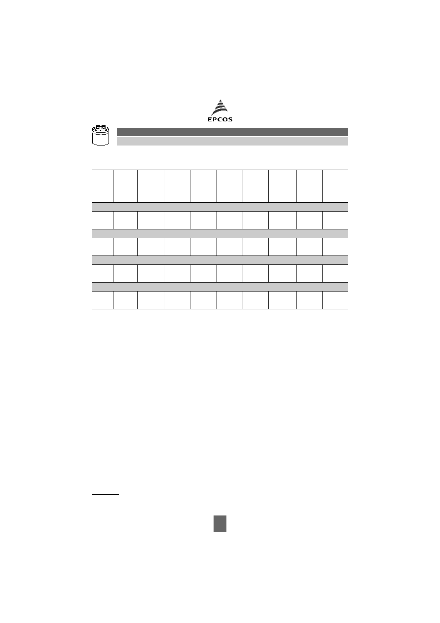
Technical data
1) Max. 50 A due to max. terminal load
55 A in case of additional terminal cooling
C
R
µF
ESR
typ
100 Hz
20
°C
m
ESR
max
100 Hz
20
°C
m
ESR
max
100 Hz
-40 °C
m
ESR
max
10 kHz
20
°C
m
Z
max
10 kHz
20
°C
m
I
~
max
(B)
10 kHz
85
°C
A
I
~
max
(B)
10 kHz
105
°C
A
I
~
R
10 kHz
125
°C
A
I
~
R
(B)
10 kHz
125
°C
A
25 VDC
12 000 21
36
234
27
28
50
1)
50
1)
7,6
20
20 000 14
24
156
18
19
50
1)
50
1)
8,5
21
40 VDC
7 500
21
36
234
27
28
50
1)
50
1)
7,6
20
12 000 15
25
162
18
19
50
1)
50
1)
8,5
21
55 VDC
4 700
23
39
234
28
30
50
1)
50
1)
7,6
20
7 500
17
29
174
23
24
50
1)
50
1)
8,5
21
63 VDC
3 900
23
39
234
28
30
50
1)
50
1)
7,6
20
6 000
17
29
174
23
24
50
1)
50
1)
8,5
21
115
10/02
B41754
Automotive
125 °C
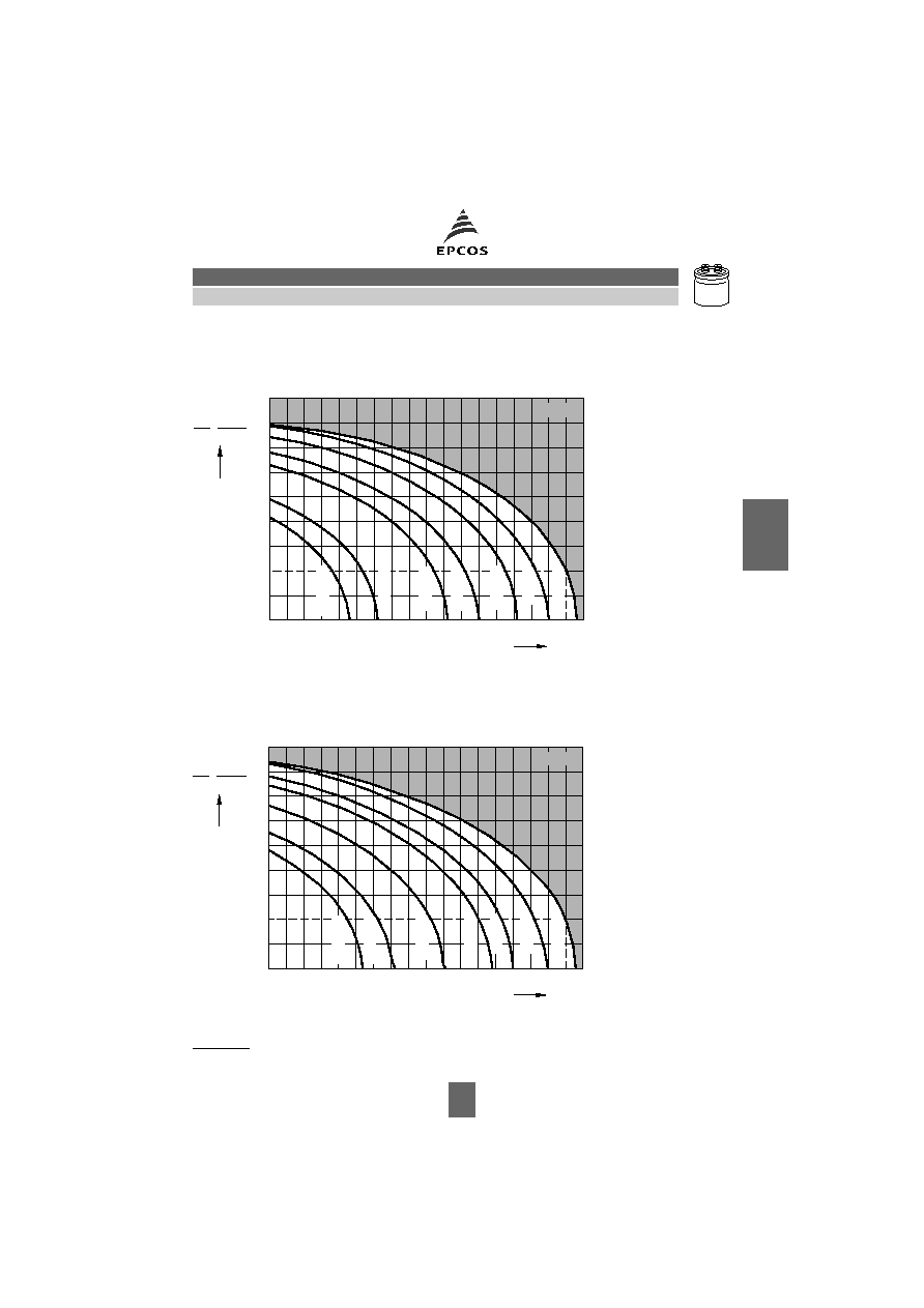
Useful life
depending on ambient temperature
T
A
(for natural cooling) and versus temperature of case base
T
B
(for base cooling) under ripple current operating conditions at
U
R
1)
Depending on ambient temperature
T
A
(for natural cooling) and versus temperature of case
base
T
B
(for base cooling) under ripple current operating conditions at
U
op
1)
U
R
= 25 V:
U
op
22 V
U
R
= 55 V:
U
op
48 V
U
R
= 40 V:
U
op
35 V
U
R
= 63 V:
U
op
55 V
3500 h rated service life at 125 °C;
up to 500 h (accumulated) operating at 150 °C in discontinous operation
50 000 h
1,5
40
0
0,5
1,0
500 000 h
50
70
60
250 000 h
80
2,5
2,0
3,0
3,5
4,5
100
25 000 h
90
10 000 h
110
°C
120
5 000 h
2 500 h
130
KAL0837-8
B41754
R
R
~
~
~
;
(B)
~
A
B
T ; T
75 000 h
1,5
40
0
0,5
1,0
50
70
500 000 h
250 000 h
60
80
2,5
2,0
3,0
3,5
4,5
7 000 h
100
25 000 h
90
110
15 000 h
°C
120
3 500 h
130
B41754
KAL0838-G
R
R
~
~
~
;
(B)
~
A
B
T ; T
1) Refer to page 40 for an explanation on how to interpret the useful life graphs.
116
10/02
B41754
Automotive
125 °C
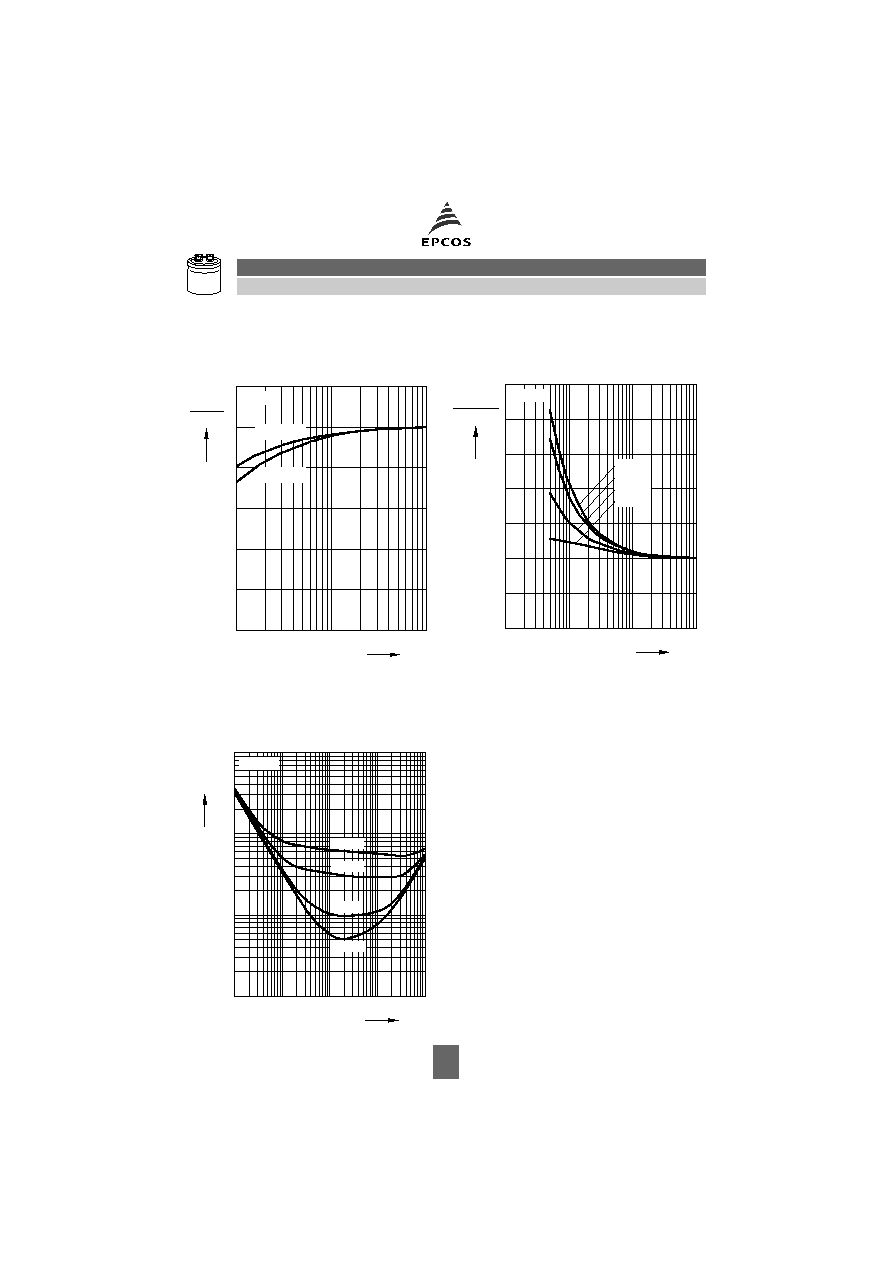
Frequency factor of permissible
ripple current
I
~
versus frequency
f
Frequency characteristics of
ESR
typical behavior
Impedance
Z
at different temperatures
T
Typical behavior for 3900
µF/63 V
KAL0839-P
10
0
2
Hz
f
~
10 kHz
~
f
25 V, 40 V
0,2
0,4
0,6
0,8
1,2
10
3
10
4
63 V, 55 V
B41754
85 °C
0
0,5
1,0
60 °C
ESR
1,5
2,0
10 kHz
2,5
ESR
3,5
f
kHz
f
KAL0840-S
10
1
10
2
3
10
10
4
20 °C
40 °C
_
B41754
10
2
Z
Hz
f
KAL0841-1
10
_
3
10
_
2
10
0
10
3
10
4
10
5
10
6
20 °C
10
_
1
105 °C
25 °C
_
40 °C
_
B41754

Herausgegeben von EPCOS AG
Unternehmenskommunikation, Postfach 80 17 09, 81617 München, DEUTSCHLAND
( ++49 89 636 09, FAX (0 89) 636-2 26 89
EPCOS AG 2002. Vervielfältigung, Veröffentlichung, Verbreitung und Verwertung dieser Broschüre und ihres Inhalts ohne aus-
drückliche Genehmigung der EPCOS AG nicht gestattet.
Bestellungen unterliegen den vom ZVEI empfohlenen Allgemeinen Lieferbedingungen für Erzeugnisse und Leistungen der Elek-
troindustrie, soweit nichts anderes vereinbart wird.
Diese Broschüre ersetzt die vorige Ausgabe.
Fragen über Technik, Preise und Liefermöglichkeiten richten Sie bitte an den Ihnen nächstgelegenen Vertrieb der EPCOS AG
oder an unsere Vertriebsgesellschaften im Ausland. Bauelemente können aufgrund technischer Erfordernisse Gefahrstoffe ent-
halten. Auskünfte darüber bitten wir unter Angabe des betreffenden Typs ebenfalls über die zuständige Vertriebsgesellschaft ein-
zuholen.
Published by EPCOS AG
Corporate Communications, P.O. Box 80 17 09, 81617 Munich, GERMANY
( ++49 89 636 09, FAX (0 89) 636-2 26 89
EPCOS AG 2002. Reproduction, publication and dissemination of this brochure and the information contained therein without
EPCOS' prior express consent is prohibited.
Purchase orders are subject to the General Conditions for the Supply of Products and Services of the Electrical and Electronics
Industry recommended by the ZVEI (German Electrical and Electronic Manufacturers' Association), unless otherwise agreed.
This brochure replaces the previous edition.
For questions on technology, prices and delivery please contact the Sales Offices of EPCOS AG or the international Representa-
tives.
Due to technical requirements components may contain dangerous substances. For information on the type in question please
also contact one of our Sales Offices.