150
10/02
Long-life grade capacitors
Applications
I
Frequency converters
I
Traction
I
Highly professional power supplies
Features
I
Maximum reliability
I
Good thermal characteristics and
high ripple current capability
I
Long useful life
I
Wide temperature range
I
All-welded construction ensures reliable
electrical contact
I
Version with optimized construction for base cooling
(2-pad solution) available
I
Version with low-inductance design available
Construction
I
Charge-discharge proof, polar
I
Aluminum case with insulating sleeve
I
Poles with screw terminal connections
I
Mounting with ring clips, clamps or threaded stud
I
The bases of types with threaded stud and
d
76,9 mm are
not insulated, types with
d
= 91 mm have fully insulated bases
KAL0567-B
B435
60 B43580
B43560
Capacitors with Screw Terminals
B43580
Compact
≠
105 ∞C
B43560, B43580

151
10/02
Compact
≠
105 ∞C
B43560 / B43580
Specifications and characteristics in brief
Ripple current capability
Due to the ripple current capability of the contact elements, the following current upper limits must
not be exceeded:
Rated voltage
U
R
Surge voltage
U
S
350 ... 450 VDC
1,10 ∑
U
R
(105 ∞C;
U
R
400 VDC, 85 ∞C;
U
R
= 450 VDC)
Rated capacitance
C
R
Capacitance tolerance
2 200 ... 15 000
µF
± 20 % M
Leakage current
I
L
(5 min, 20 ∞C)
Self-inductance
ESL
d
= 51,6 mm: approx. 15 nH
d
64,3 mm: approx. 20 nH
Capacitors with low-inductance design:
d
64,3 mm: approx. 13 nH
Useful life
105 ∞C;
U
R
;
I
~
R
85 ∞C;
U
R
;
I
~
R
40 ∞C;
U
R
; 2,2 ∑
I
~
R
>
6 000 h
> 20 000 h
> 250 000 h
Requirements:
C
/
C
± 30 % of initial value
ESR
3 times initial specified limit
I
L
initial specified limit
Failure percentage:
1 %
Failure rate:
20 fit ( 20 ∑ 10
≠9
/h)
(for definiton "fit", refer to chapter
"Quality"
, page 62)
Voltage endurance test
105 ∞C;
U
R
;
I
~
R
2 000 h
Post test requirements:
C
/
C
± 10 % of initial value
ESR
1,3 times initial specified limit
I
L
initial specified limit
Vibration resistance
To IEC 60068-2-6, test Fc:
displacement amplitude 0,75 mm, frequency range 10 to 55 Hz,
acceleration max. 10
g
, duration 3
◊ 2 h
IEC climatic category
To IEC 60068-1:
40/105/56 (≠ 40 ∞C/+ 105 ∞C/56 days damp heat test)
Detail specifications
Sectional specification
Similar to CECC 30301-803, CECC 30301-807
IEC 60384-4
Capacitor diameter
64,3 mm
76,9 mm
91,0 mm
I
~
max
40 A
50 A
70 A
I
L
0,3
µA
C
R
µF
-------
U
R
V
-------
Ë
¯
Ê
ˆ
0,7
4
µA
+

152
10/02
Compact
≠
105 ∞C
B43560 / B43580
Dimensional drawings
Type B43560
Type B43580
Ring clip/clamp mounting
Threaded stud mounting
Positive pole marking: +
The base of all types with threaded stud and
d
= 91 mm is fully insulated (the lengths
l
and
l
1
are
increased by 0,5 mm in these cases). For types with threaded stud and
d
76 mm the base is not
insulated. Also refer to the notes on mounting given on page 168.
Dimensions and weights
Dimensions are also valid for 2-pad solution and low-inductance design.
Packing (For ecological reasons the packing is pure cardboard.)
Ter-
minal
Dimensions (mm) with insulating sleeve
Approx.
wt. (g)
d
I
± 1
I
1
± 1
I
2
+ 0
l
3
d
1
d
2
max
d
3
max
a
+ 0,2
≠ 1
≠ 0,4
M 5
M 5
M 5
64,3
+ 0/≠ 0,8
64,3
+ 0/≠ 0,8
64,3
+ 0/≠ 0,8
105,7
130,7
143,2
112,2
137,2
149,7
17
17
17
7,0
+ 0,2/≠ 1
7,0
+ 0,2/≠ 1
7,0
+ 0,2/≠ 1
M 12
M 12
M 12
8,2
8,2
8,2
13,5
13,5
13,5
28,5
28,5
28,5
440
570
640
M 6
M 6
M 6
M 6
M 6
76,9
+ 0/≠ 0,7
76,9
+ 0/≠ 0,7
76,9
+ 0/≠ 0,7
76,9
+ 0/≠ 0,7
76,9
+ 0/≠ 0,7
105,7
130,7
143,2
168,7
220,7
111,5
136,5
149,0
174,5
226,5
17
17
17
17
17
6,4
+ 1,1/≠ 0,8
6,4
+ 1,1/≠ 0,8
6,4
+ 1,1/≠ 0,8
6,4
+ 1,1/≠ 0,8
6,4
+ 1,1/≠ 0,8
M 12
M 12
M 12
M 12
M 12
17,7
17,7
17,7
17,7
17,7
17,7
17,7
17,7
17,7
17,7
31,7
31,7
31,7
31,7
31,7
540
750
840
1000
1300
M 6
M 6
M 6
M 6
91,0
+ 0/≠ 2
91,0
+ 0/≠ 2
91,0
+ 0/≠ 2
91,0
+ 0/≠ 2
144,5
170,0
191,0
221,0
149,8
175,3
196,3
226,3
17
17
17
17
6,4
+ 1,1/≠ 0,8
6,4
+ 1,1/≠ 0,8
6,4
+ 1,1/≠ 0,8
6,4
+ 1,1/≠ 0,8
M 12
M 12
M 12
M 12
17,7
17,7
17,7
17,7
17,7
17,7
17,7
17,7
31,7
31,7
31,7
31,7
1200
1500
1700
1900
Capacitor diameter
d
Packing units (pieces)
64,3 mm
76,9 mm
91,0 mm
15
12
8
M5: min. reach of screw = 8 mm
M6: min. reach of screw = 12 mm*)
*) 8 mm for low-inductance design
153
10/02
Compact
≠
105 ∞C
B43560 / B43580
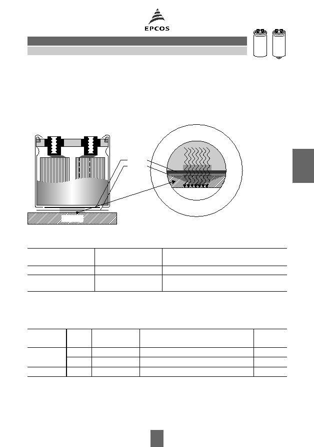
Special designs
I
Low-inductance design
I
2-pad solution
Design for optimized connection of the capacitor to the heatsink when using base cooling.
This version is available for capacitors without threaded stud and for diameters
64,3 mm
(cf.
I
~
R
(B) in table "Technical data and ordering codes" and useful life graphs).
Ordering codes:
Accessories
The following items are included in the delivery package, but are not fastened to the capacitors:
The following must be ordered separately:
Ring clips
B 44 030 (cf. page 169)
Clamps for capacitors with
d
64,3 mm
B 44 030 (cf. page 173)
Insulating parts
B 44 020 (cf. page 166)
Design
Identification in 3rd
block of ordering code
Remark
Low inductance (13 nH)
M003
For capacitors with diameter
d
64,3 mm
2-pad solution
M006
For capacitors with diameter
d
64,3 mm and
without threaded stud
Thread
Toothed
washers
Screws/Nuts
Maximum
torque
For terminals
M 5
A 5,1 DIN 6797
Cylinder-head screw M 5
◊ 8 DIN 84-4.8
2
Nm
M 6
A 6,4 DIN 6797
Cylinder-head screw M 6
◊ 12 DIN 85-4.8 2,5 Nm
For mounting
M 12
J 12,5 DIN 6797 Hex nut BM 12 DIN 439
10
Nm
Heatsink
Thermopad
thickness
0,2 mm
0,5 mm
KAL0823-3-E

154
10/02
Compact
≠
105 ∞C
B43560 / B43580
Overview of available types
The capacitance and voltage ratings listed above are available in different cases upon request.
Other voltage and capacitance ratings are also available upon request.
U
R
(VDC)
350
400
450
C
R
(
µF)
Case dimensions
d
◊
l
(mm)
2 200
64,3
◊ 105,7
64,3
◊ 130,7
2 700
64,3
◊ 105,7
3 300
64,3
◊ 130,7
76,9
◊ 130,7
3 900
76,9
◊ 105,7
4 700
64,3
◊ 143,2
76,9
◊ 105,7
76,9
◊ 130,7
76,9
◊ 168,7
91,0
◊ 144,5
6 000
76,9
◊ 130,7
76,9
◊ 220,7
6 800
76,9
◊ 143,2
91,0
◊ 144,5
91,0
◊ 191,0
8 200
91,0
◊ 144,5
91,0
◊ 170,0
76,9
◊ 220,7
91,0
◊ 221,0
10 000
76,9
◊ 220,7
12 000
91,0
◊ 221,0
15 000
91,0
◊ 221,0