
PTC thermistors
Limit temperature sensors,
leaded disks, coated
Series/Type:
B59008
Date:
March 2006
© EPCOS AG 2006. Reproduction, publication and dissemination of this publication, enclosures hereto and the
information contained therein without EPCOS' prior express consent is prohibited.
Applications
Limit temperature monitoring
Features
Tinned leads
Marked with coded nominal threshold temperature
Characteristics for nominal threshold temperatures T
NTT
= 90 to 160
°
C conform with DIN 44081
Extremely fast response due to small dimensions
UL approval to UL 1434 (file number E69802)
RoHS-compatible
Delivery mode
Bulk (standard)
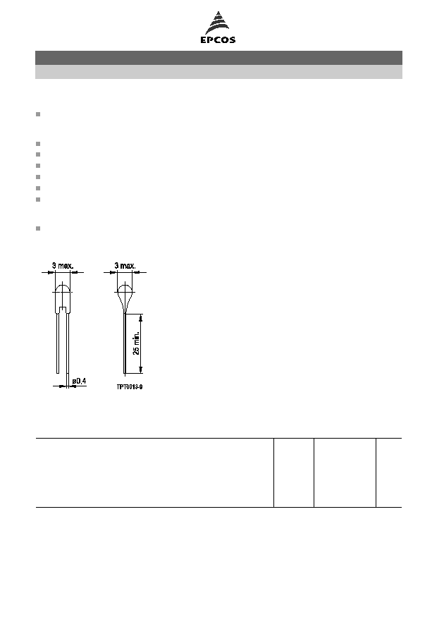
Dimensional drawing
Dimensions in mm
General technical data
Max. operating voltage
(T
A
= 0 ... 40
°
C)
V
max
30
VDC
Max. measuring voltage
(T
A
=
25
°
C ... T
NTT
+23 K) V
meas,max
7.5
VDC
Rated resistance
(V
PTC
2.5 V)
R
R
250
Thermal threshold time
t
a
<3
s
Operating temperature range
(V
V
meas,max
)
T
op
40/ T
NTT
+23
°
C
Operating temperature range
(V = V
max
)
T
op
0/+40
°
C
Sensors
Limit temperature sensors, leaded disks, coated
C8
Page 2 of 7
Please read Important notes and
Cautions and warnings at the end of this document.
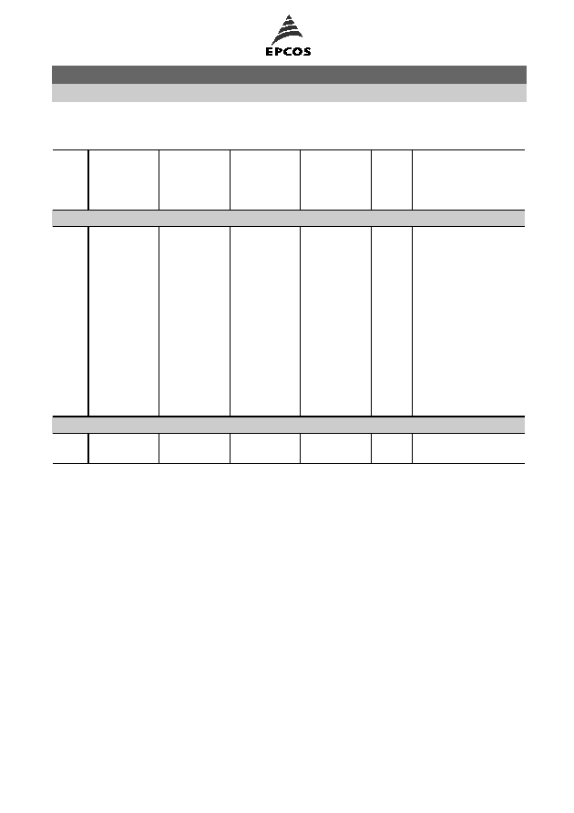
Electrical specifications and ordering codes
T
NTT
°
C
R
(T
NTT
T)
(V
PTC
2.5 V)
R
(T
NTT
+
T)
(V
PTC
2.5 V)
R
(T
NTT
+ 15 K)
(V
PTC
7.5 V)
R
(T
NTT
+ 23 K)
(V
PTC
2.5 V)
Stamp
code
Ordering code
T = 5 K
60
570
570
-
4 k
f
B59008C0060A040
70
570
570
-
4 k
g
B59008C0070A040
80
570
570
-
4 k
h
B59008C0080A040
90
550
1330
4 k
-
i
B59008C0090A040
100
550
1330
4 k
-
j
B59008C0100A040
110
550
1330
4 k
-
k
B59008C0110A040
120
550
1330
4 k
-
l
B59008C0120A040
130
550
1330
4 k
-
m
B59008C0130A040
140
550
1330
4 k
-
n
B59008C0140A040
145
550
1330
4 k
-
o
B59008C0145A040
150
550
1330
4 k
-
p
B59008C0150A040
155
550
1330
4 k
-
r
B59008C0155A040
160
550
1330
4 k
-
s
B59008C0160A040
T = 7 K
170
570
570
-
4 k
t
B59008C0170A040
180
570
570
-
4 k
u
B59008C0180A040
Sensors
Limit temperature sensors, leaded disks, coated
C8
Page 3 of 7
Please read Important notes and
Cautions and warnings at the end of this document.
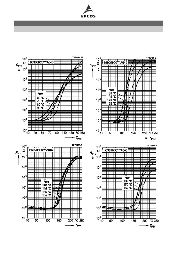
Characteristics (typical)
PTC resistance R
PTC
versus PTC temperature T
PTC
(measured at low signal voltage)
Sensors
Limit temperature sensors, leaded disks, coated
C8
Page 4 of 7
Please read Important notes and
Cautions and warnings at the end of this document.
Cautions and warnings
General
EPCOS thermistors are designed for specific applications and should not be used for purposes
not identified in our specifications, application notes and data books unless otherwise agreed
with EPCOS during the design-in-phase.
Ensure suitability of thermistor through reliability testing during the design-in phase. The
thermistors should be evaluated taking into consideration worst-case conditions.
Storage
Store thermistors only in original packaging. Do not open the package before storage.
Storage conditions in original packaging: storage temperature
25
°
C ... +45
°
C, relative
humidity
75% annual mean, maximum 95%, dew precipitation is inadmissible.
Avoid contamination of thermistors surface during storage, handling and processing.
Avoid storage of thermistor in harmful environment with effect on function on long-term
operation (examples given under operation precautions).
Use thermistor within 6 months after delivery.
Handling
PTCs must not be dropped. Chip-offs must not be caused during handling of PTCs.
Components must not be touched with bare hands. Gloves are recommended.
Avoid contamination of thermistor surface during handling.
Soldering
Use rosin-type flux or non-activated flux.
Insufficient preheating may cause ceramic cracks.
Rapid cooling by dipping in solvent is not recommended.
Complete removal of flux is recommended.
Mounting
Electrode must not be scratched before/during/after the mounting process.
Contacts and housing used for assembly with thermistor have to be clean before mounting.
Especially grease or oil must be removed.
When PTC thermistors are encapsulated with sealing material, the precautions given in chapter
"Mounting instructions", "Sealing and potting" must be observed.
When the thermistor is mounted, there must not be any foreign body between the electrode of
the thermistor and the clamping contact.
The minimum force of the clamping contacts pressing against the PTC must be 10 N.
During operation, the thermistor's surface temperature can be very high. Ensure that adjacent
components are placed at a sufficient distance from the thermistor to allow for proper cooling at
the thermistors.
Ensure that adjacent materials are designed for operation at temperatures comparable to the
surface temperature of thermistor. Be sure that surrounding parts and materials can withstand
this temperature.
Avoid contamination of thermistor surface during processing.
Sensors
Limit temperature sensors, leaded disks, coated
C8
Page 5 of 7
Please read Important notes and
Cautions and warnings at the end of this document.