
PTC thermistors for switching
applications
Energy-saving lamps
Series/Type:
B59119, B59082, B59097
Date:
March 2006
© EPCOS AG 2006. Reproduction, publication and dissemination of this publication, enclosures hereto and the
information contained therein without EPCOS' prior express consent is prohibited.
Applications
Switching PTC thermistor for preheating of
the electrodes in energy-saving lamps
Features
Coated thermistor disk, kinked leads
Long product life: stable performance
throughout at least 30 000 switching cycles
Marked with manufacturer's logo and type
designation
RoHS compatible
Delivery mode
Cardboard strips (standard); cardboard tape
reeled or in AMMO pack on request
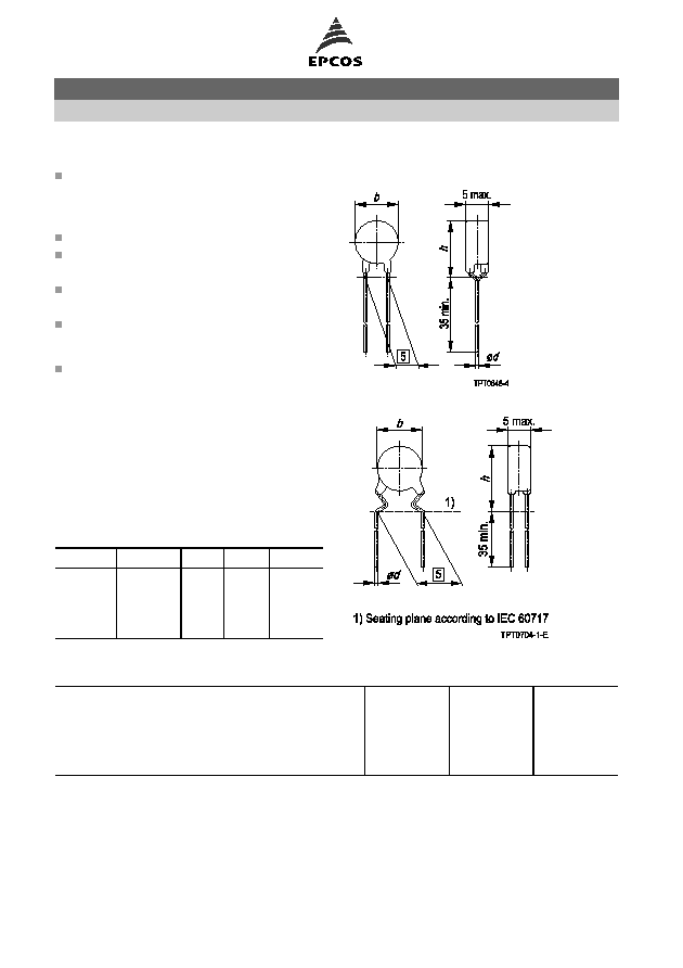
Dimensional drawings
C1119/ S1097
S1082
Dimensions (mm)
Type
T
ref
(
∞
C)
b
max
h
max
d
C1119
80
4.0
7.5
0.5
C1119
120
4.0
7.5
0.5
S1082
80
6.5
10.1
0.6
S1097
55
4.0
7.5
0.5
General technical data
Switching cycles
N
>30000
Tolerance of R
R
R
R
±
25
%
Frequency
f
70
kHz
Operating temperature range
(V = 0)
T
op
25/+125
∞
C
Operating temperature range
(V = V
max
)
T
op
10/+80
∞
C
Switching applications
for energy-saving lamps
C1119, S1097, S1082
Page 2 of 6
Please read Important notes and
Cautions and warnings at the end of this document.

Electrical specifications and ordering codes
Type
R
R
V
max
(t
200 ms)
V
RMS
I
Smax
(V = V
max
)
mA
t
s
@ I
Smax
s
T
ref
∞
C
Ordering code
C1119
150
310
200
0.6
80
B59119C1080A070
C1119
150
310
200
1.2
120
B59119C1120A070
S1097
340
310
200
0.25
55
B59097S1055B070
S1082
1500
550
100
1.1
80
B59082S1080B070
Characteristics (typical)
PTC resistance R
PTC
versus
PTC temperature T
PTC
(measured at low signal voltage)
Switching time t
S
versus switching current I
S
(measured at 25
∞
C in still air)
Switching applications
for energy-saving lamps
C1119, S1097, S1082
Page 3 of 6
Please read Important notes and
Cautions and warnings at the end of this document.

Cautions and warnings
General
EPCOS thermistors are designed for specific applications and should not be used for purposes
not identified in our specifications, application notes and data books unless otherwise agreed
with EPCOS during the design-in-phase.
Ensure suitability of thermistor through reliability testing during the design-in phase. The
thermistors should be evaluated taking into consideration worst-case conditions.
Storage
Store thermistors only in original packaging. Do not open the package before storage.
Storage conditions in original packaging: storage temperature
25
∞
C ... +45
∞
C, relative
humidity
75% annual mean, maximum 95%, dew precipitation is inadmissible.
Avoid contamination of thermistors surface during storage, handling and processing.
Avoid storage of thermistor in harmful environment with effect on function on long-term
operation (examples given under operation precautions).
Use thermistor within 6 months after delivery.
Handling
PTCs must not be dropped. Chip-offs must not be caused during handling of PTCs.
Components must not be touched with bare hands. Gloves are recommended.
Avoid contamination of thermistor surface during handling.
Soldering
Use rosin-type flux or non-activated flux.
Insufficient preheating may cause ceramic cracks.
Rapid cooling by dipping in solvent is not recommended.
Complete removal of flux is recommended.
Mounting
Electrode must not be scratched before/during/after the mounting process.
Contacts and housing used for assembly with thermistor have to be clean before mounting.
Especially grease or oil must be removed.
When PTC thermistors are encapsulated with sealing material, the precautions given in chapter
"Mounting instructions", "Sealing and potting" must be observed.
When the thermistor is mounted, there must not be any foreign body between the electrode of
the thermistor and the clamping contact.
The minimum force of the clamping contacts pressing against the PTC must be 10 N.
During operation, the thermistor's surface temperature can be very high. Ensure that adjacent
components are placed at a sufficient distance from the thermistor to allow for proper cooling at
the thermistors.
Ensure that adjacent materials are designed for operation at temperatures comparable to the
surface temperature of thermistor. Be sure that surrounding parts and materials can withstand
this temperature.
Avoid contamination of thermistor surface during processing.
Switching applications
for energy-saving lamps
C1119, S1097, S1082
Page 4 of 6
Please read Important notes and
Cautions and warnings at the end of this document.

Operation
Use thermistors only within the specified temperature operating range.
Use thermistors only within the specified voltage and current ranges.
Environmental conditions must not harm the thermistors. Use thermistors only in normal
atmospheric conditions. Avoid use in deoxidizing gases (chlorine gas, hydrogen sulfide gas,
ammonia gas, sulfuric acid gas etc), corrosive agents, humid or salty conditions.Contact with
any liquids and solvents should be prevented.
Be sure to provide an appropriate fail-safe function to prevent secondary product damage
caused by abnormal function (e.g. use VDR for limitation of overvoltage condition).
Switching applications
for energy-saving lamps
C1119, S1097, S1082
Page 5 of 6
Please read Important notes and
Cautions and warnings at the end of this document.