
PTC thermistors for switching
applications
Plastic case, 63 V to 220 V
Series/Type:
B59339
Date:
March 2006
© EPCOS AG 2006. Reproduction, publication and dissemination of this publication, enclosures hereto and the
information contained therein without EPCOS' prior express consent is prohibited.

Applications
Delayed switching of loads
For frequent switching
Features
Encased thermistor disk with clamp contacts
Flame-retardant plastic case
Case material UL-listed
Silver-plated lead-free solder pins
Manufacturer's logo and type designation
stamped on in white
Stable performance throughout
100000 switching cycles
RoHS-compatible
Delivery mode
Packed in blister trays
Dimensional drawing
Dimensions in mm
General technical data
Switching cycles
N
100000
Switching time
t
S
0.5
s
Tolerance of R
R
R
R
±
25
%
Operating temperature range
(V = 0)
T
op
25/+125
∞
C
Operating temperature range
(V = V
max
)
T
op
0/+60
∞
C
Electrical specifications and ordering codes
Type
T
ref
∞
C
I
R
mA
I
S
mA
I
Smax
(V = V
max
)
A
I
r
(V = V
max
)
mA
R
R
R
min
Ordering code
V
max
= 80 V , V
R
= 63 V
J280
120
77
150
1.10
14
32
20
B59339A1320P020
J281
120
60
120
0.90
10
50
31
B59339A1500P020
V
max
= 160 V , V
R
= 110 V
J282
120
48
100
0.70
6.0
80
50
B59339A1800P020
J283
120
39
80
0.58
5.0
120
75
B59339A1121P020
V
max
= 265 V , V
R
= 220 V
J284
120
30
60
0.42
4.0
200
110
B59339A1201P020
J285
120
24
50
0.33
4.0
320
200
B59339A1321P020
J286
120
20
40
0.27
3.5
500
260
B59339A1501P020
J287
120
15
30
0.22
3.0
800
480
B59339A1801P020
J288
120
13
26
0.18
2.5
1200
630
B59339A1122P020
J289
120
10
20
0.15
2.0
2000
900
B59339A1202P020
J290
115
8
16
0.12
1.5
3200
1500
B59339A1322P020
Switching applications
PTC thermistors in plastic case, 63 V to 220 V
J280 ... J290
Page 2 of 8
Please read Important notes and
Cautions and warnings at the end of this document.

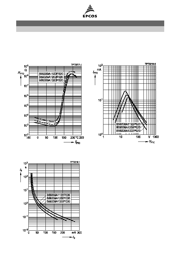
Characteristics (typical)
PTC resistance R
PTC
versus
PTC temperature T
PTC
(measured at low signal voltage)
PTC current I
PTC
versus PTC voltage V
PTC
(measured at 25
∞
C in still air)
Switching time t
S
versus switching current I
S
(measured at 25
∞
C in still air)
Switching applications
PTC thermistors in plastic case, 63 V to 220 V
J280 ... J290
Page 3 of 8
Please read Important notes and
Cautions and warnings at the end of this document.

Characteristics (typical)
PTC resistance R
PTC
versus
PTC temperature T
PTC
(measured at low signal voltage)
PTC current I
PTC
versus PTC voltage V
PTC
(measured at 25
∞
C in still air)
Switching time t
S
versus switching current I
S
(measured at 25
∞
C in still air)
Switching applications
PTC thermistors in plastic case, 63 V to 220 V
J280 ... J290
Page 4 of 8
Please read Important notes and
Cautions and warnings at the end of this document.
Characteristics (typical)
PTC resistance R
PTC
versus
PTC temperature T
PTC
(measured at low signal voltage)
PTC current I
PTC
versus PTC voltage V
PTC
(measured at 25
∞
C in still air)
Switching time t
S
versus switching current I
S
(measured at 25
∞
C in still air)
Switching applications
PTC thermistors in plastic case, 63 V to 220 V
J280 ... J290
Page 5 of 8
Please read Important notes and
Cautions and warnings at the end of this document.

Cautions and warnings
General
EPCOS thermistors are designed for specific applications and should not be used for purposes
not identified in our specifications, application notes and data books unless otherwise agreed
with EPCOS during the design-in-phase.
Ensure suitability of thermistor through reliability testing during the design-in phase. The
thermistors should be evaluated taking into consideration worst-case conditions.
Storage
Store thermistors only in original packaging. Do not open the package before storage.
Storage conditions in original packaging: storage temperature
25
∞
C ... +45
∞
C, relative
humidity
75% annual mean, maximum 95%, dew precipitation is inadmissible.
Avoid contamination of thermistors surface during storage, handling and processing.
Avoid storage of thermistor in harmful environment with effect on function on long-term
operation (examples given under operation precautions).
Use thermistor within 6 months after delivery.
Handling
PTCs must not be dropped. Chip-offs must not be caused during handling of PTCs.
Components must not be touched with bare hands. Gloves are recommended.
Avoid contamination of thermistor surface during handling.
Soldering
Use rosin-type flux or non-activated flux.
Insufficient preheating may cause ceramic cracks.
Rapid cooling by dipping in solvent is not recommended.
Complete removal of flux is recommended.
Mounting
Electrode must not be scratched before/during/after the mounting process.
Contacts and housing used for assembly with thermistor have to be clean before mounting.
Especially grease or oil must be removed.
When PTC thermistors are encapsulated with sealing material, the precautions given in chapter
"Mounting instructions", "Sealing and potting" must be observed.
When the thermistor is mounted, there must not be any foreign body between the electrode of
the thermistor and the clamping contact.
The minimum force of the clamping contacts pressing against the PTC must be 10 N.
During operation, the thermistor's surface temperature can be very high. Ensure that adjacent
components are placed at a sufficient distance from the thermistor to allow for proper cooling at
the thermistors.
Ensure that adjacent materials are designed for operation at temperatures comparable to the
surface temperature of thermistor. Be sure that surrounding parts and materials can withstand
this temperature.
Avoid contamination of thermistor surface during processing.
Switching applications
PTC thermistors in plastic case, 63 V to 220 V
J280 ... J290
Page 6 of 8
Please read Important notes and
Cautions and warnings at the end of this document.

Operation
Use thermistors only within the specified temperature operating range.
Use thermistors only within the specified voltage and current ranges.
Environmental conditions must not harm the thermistors. Use thermistors only in normal
atmospheric conditions. Avoid use in deoxidizing gases (chlorine gas, hydrogen sulfide gas,
ammonia gas, sulfuric acid gas etc), corrosive agents, humid or salty conditions.Contact with
any liquids and solvents should be prevented.
Be sure to provide an appropriate fail-safe function to prevent secondary product damage
caused by abnormal function (e.g. use VDR for limitation of overvoltage condition).
Switching applications
PTC thermistors in plastic case, 63 V to 220 V
J280 ... J290
Page 7 of 8
Please read Important notes and
Cautions and warnings at the end of this document.

The following applies to all products named in this publication:
1.
Some parts of this publication contain statements about the suitability of our products for
certain areas of application. These statements are based on our knowledge of typical re-
quirements that are often placed on our products in the areas of application concerned. We
nevertheless expressly point out that such statements cannot be regarded as binding
statements about the suitability of our products for a particular customer application.
As a rule, EPCOS is either unfamiliar with individual customer applications or less familiar
with them than the customers themselves. For these reasons, it is always ultimately incum-
bent on the customer to check and decide whether an EPCOS product with the properties de-
scribed in the product specification is suitable for use in a particular customer application.
2.
We also point out that in individual cases, a malfunction of passive electronic compon-
ents or failure before the end of their usual service life cannot be completely ruled out
in the current state of the art, even if they are operated as specified. In customer applica-
tions requiring a very high level of operational safety and especially in customer applications
in which the malfunction or failure of a passive electronic component could endanger human
life or health (e.g. in accident prevention or life-saving systems), it must therefore be ensured
by means of suitable design of the customer application or other action taken by the customer
(e.g. installation of protective circuitry or redundancy) that no injury or damage is sustained by
third parties in the event of malfunction or failure of a passive electronic component.
3.
The warnings, cautions and product-specific notes must be observed.
4.
In order to satisfy certain technical requirements, some of the products described in this
publication may contain substances subject to restrictions in certain jurisdictions (e.g.
because they are classed as "hazardous"). Useful information on this will be found in our
Material Data Sheets on the Internet (www.epcos.com/material). Should you have any more
detailed questions, please contact our sales offices.
5.
We constantly strive to improve our products. Consequently, the products described in this
publication may change from time to time. The same is true of the corresponding product
specifications. Please check therefore to what extent product descriptions and specifications
contained in this publication are still applicable before or when you place an or-
der.
We also reserve the right to discontinue production and delivery of products. Con-
sequently, we cannot guarantee that all products named in this publication will always be
available.
6.
Unless otherwise agreed in individual contracts, all orders are subject to the current ver-
sion of the "General Terms of Delivery for Products and Services in the Electrical In-
dustry" published by the German Electrical and Electronics Industry Association
(ZVEI).
7.
The trade names EPCOS, EPCOS-JONES, Baoke, CeraDiode, CSSP, MLSC, PhaseCap,
PhaseMod, SIFI, SIKOREL, SilverCap, SIMID, SIOV, SIP5D, SIP5K, UltraCap, WindCap are
trademarks registered or pending in Europe and in other countries. Further information will
be found on the Internet at www.epcos.com/trademarks.
Important notes
Page 8 of 8