
PTC thermistors for overcurrent
protection
Leaded disks, coated,
42 V power net
Series/Type:
B599*3
Date:
March 2006
© EPCOS AG 2006. Reproduction, publication and dissemination of this publication, enclosures hereto and the
information contained therein without EPCOS' prior express consent is prohibited.
1) To ISO/TC22 WD24V-1E
2) Peak value of maximum DC operating voltage, incl. ripple.
Applications
Overcurrent protection for 42 V power net
Features
Lead-free terminals
Manufacturer's logo and type designation
stamped on in white
RoHS-compatible
Options
Leadless disks and leaded disks without
coating available on request
Thermistors with diameter b
11.0 mm are
also available on tape (to IEC 60286-2)
Delivery mode
Cardboard strips (standard)
Cardboard tape reeled or in Ammo pack on
request
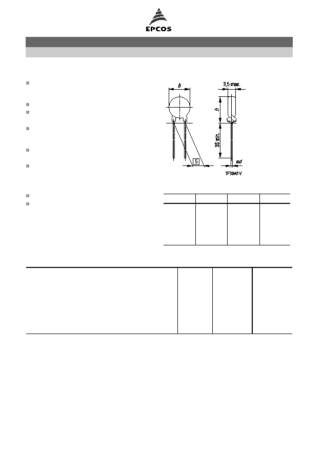
Dimensional drawing
Dimensions (mm)
Type
b
max
h
max
d
C943
17.5
21.0
0.6
C953
13.5
17.0
0.6
C963
11.0
14.5
0.6
C973
9.0
12.5
0.6
C983
6.5
10.0
0.6
General technical data
Max. operating voltage
(T
A
= 125
∞
C)
V
max
1)
54
VDC
Max. operating voltage
(t
400 ms)
V
max,dyn
2)
58
V
Rated voltage
V
R
42
VDC
Switching cycles
N
100
Reference temperature
(typ.)
T
ref
120
∞
C
Tolerance of R
R
R
R
±
20
%
Operating temperature range
(V = 0)
T
op
40/+125
∞
C
Operating temperature range
(V = V
max
)
T
op
40/+125
∞
C
Overcurrent protection
Leaded disks, coated, 42 V power net
C943 ... C983
Page 2 of 7
Please read Important notes and
Cautions and warnings at the end of this document.

Electrical specifications and ordering codes
Type
I
R
mA
I
S
mA
I
Smax
(V = V
max
)
A
I
r
(V = V
max
)
typ.
mA
R
R
R
min
Ordering code
C943
750
1300
8.0
50
1.0
0.7
B59943C0120A070
C953
430
770
6.0
40
1.8
1.2
B59953C0120A070
C963
320
560
5.0
30
2.7
1.8
B59963C0120A070
C973
230
410
4.0
20
4.2
2.9
B59973C0120A070
C983
140
240
2.0
15
10.0
6.8
B59983C0120A070
Overcurrent protection
Leaded disks, coated, 42 V power net
C943 ... C983
Page 3 of 7
Please read Important notes and
Cautions and warnings at the end of this document.

Characteristics (typical)
PTC resistance R
PTC
versus
PTC temperature T
PTC
(measured at low signal voltage)
PTC current I
PTC
versus PTC voltage V
PTC
(measured at 25
∞
C in still air)
Switching time t
S
versus switching current I
S
(measured at 25
∞
C in still air)
Rated current I
R
versus ambient temperature T
A
(measured in still air)
Overcurrent protection
Leaded disks, coated, 42 V power net
C943 ... C983
Page 4 of 7
Please read Important notes and
Cautions and warnings at the end of this document.

Cautions and warnings
General
EPCOS thermistors are designed for specific applications and should not be used for purposes
not identified in our specifications, application notes and data books unless otherwise agreed
with EPCOS during the design-in-phase.
Ensure suitability of thermistor through reliability testing during the design-in phase. The
thermistors should be evaluated taking into consideration worst-case conditions.
Storage
Store thermistors only in original packaging. Do not open the package before storage.
Storage conditions in original packaging: storage temperature
25
∞
C ... +45
∞
C, relative
humidity
75% annual mean, maximum 95%, dew precipitation is inadmissible.
Avoid contamination of thermistors surface during storage, handling and processing.
Avoid storage of thermistor in harmful environment with effect on function on long-term
operation (examples given under operation precautions).
Use thermistor within 6 months after delivery.
Handling
PTCs must not be dropped. Chip-offs must not be caused during handling of PTCs.
Components must not be touched with bare hands. Gloves are recommended.
Avoid contamination of thermistor surface during handling.
Soldering
Use rosin-type flux or non-activated flux.
Insufficient preheating may cause ceramic cracks.
Rapid cooling by dipping in solvent is not recommended.
Complete removal of flux is recommended.
Mounting
Electrode must not be scratched before/during/after the mounting process.
Contacts and housing used for assembly with thermistor have to be clean before mounting.
Especially grease or oil must be removed.
When PTC thermistors are encapsulated with sealing material, the precautions given in chapter
"Mounting instructions", "Sealing and potting" must be observed.
When the thermistor is mounted, there must not be any foreign body between the electrode of
the thermistor and the clamping contact.
The minimum force of the clamping contacts pressing against the PTC must be 10 N.
During operation, the thermistor's surface temperature can be very high. Ensure that adjacent
components are placed at a sufficient distance from the thermistor to allow for proper cooling at
the thermistors.
Ensure that adjacent materials are designed for operation at temperatures comparable to the
surface temperature of thermistor. Be sure that surrounding parts and materials can withstand
this temperature.
Avoid contamination of thermistor surface during processing.
Overcurrent protection
Leaded disks, coated, 42 V power net
C943 ... C983
Page 5 of 7
Please read Important notes and
Cautions and warnings at the end of this document.