
Data Sheet
Data Sheet
Date:
September 2006
EPCOS AG 2006. Reproduction, publication and dissemination of this data sheet and the
information contained therein without EPCOS' prior express consent is prohibited.
Ferrites and accessories
PM 62/49
Core and accessories
Series/Type:
B65684, B65685

2
09/06
Please read Cautions and warnings and
Important notes at the end of this document.
To IEC 61247
Particularly suitable for power transformers
and energy storage chokes
Delivery mode: sets
Magnetic characteristics (per set)
l/A = 0.191 mm
≠1
l
e
= 109 mm
A
e
= 570 mm
2
A
min
= 470 mm
2
V
e
= 62000 mm
3
Approx. weight 280 g/set
Gapped
Ungapped
Material
A
L
value
nH
s
approx.
mm
µ
e
Ordering code
N27
315
±3%
2.60
48
B65684A0315A027
630
±3%
1.10
95
B65684A0630A027
Material
A
L
value
nH
µ
e
P
V
W/set
Ordering code
N27
9200 +30/≠20%
1400
< 9.5 (200 mT, 25 kHz, 100
∞C) B65684A0000R027
N87
9200 +30/≠20%
1400
< 5.8 (200 mT, 100 kHz, 100
∞C) B65684A0000R087
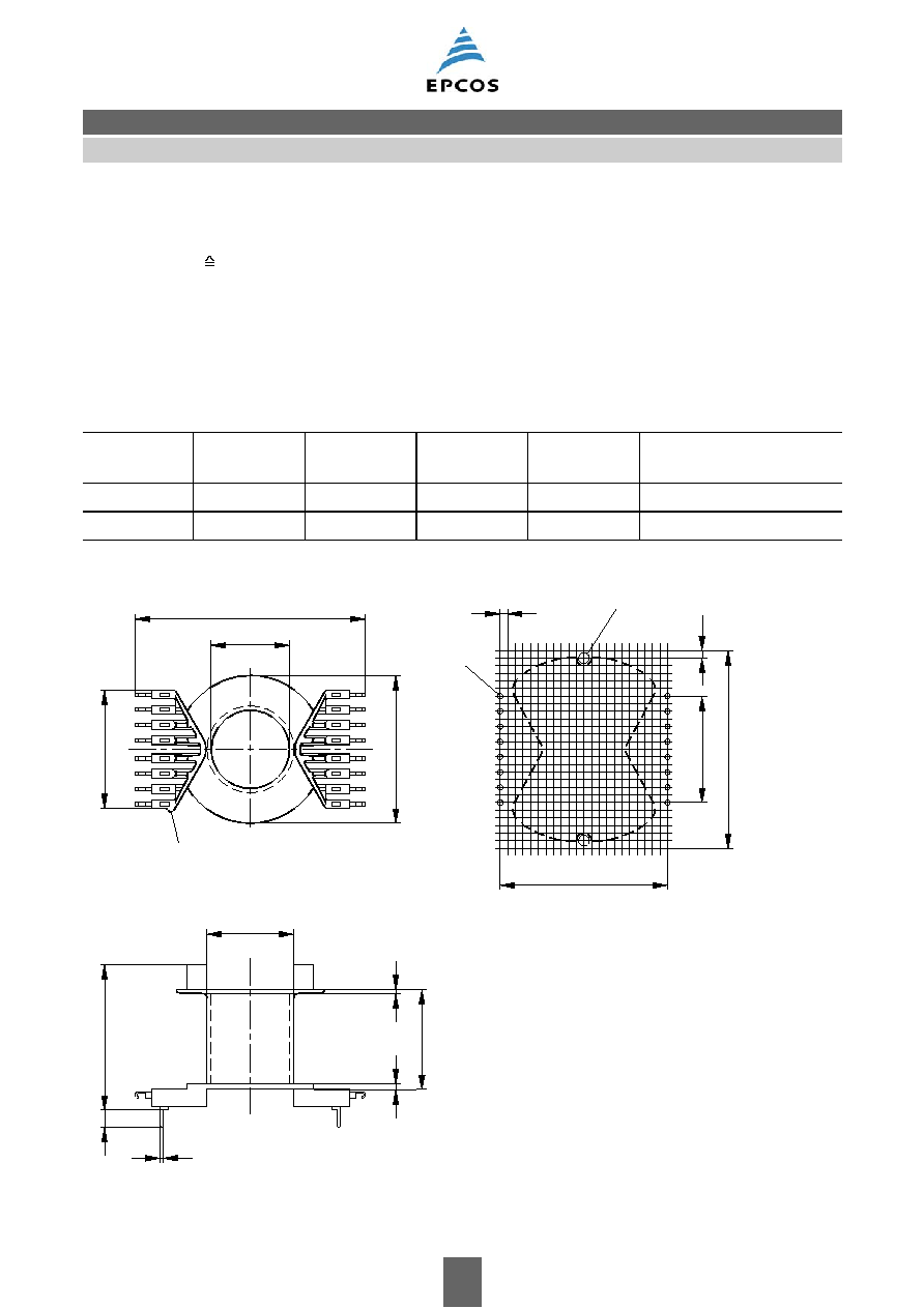
FPM0024-2
> 29
< 28.5
4+1
48.8+1.5
1.2+0.2
62 2
_
¯5.4+0.2
¯25.5 0.8
_
33.4+0.8
49
0.4
_
s
B65684
Core
PM 62/49
3
09/06
Please read Cautions and warnings and
Important notes at the end of this document.
Coil former
Material:
GFR polyterephthalate (UL 94 V-0, insulation class to IEC 60085:
F max. operating temperature 155
∞C), color code black
Valox 420-SE0
Æ
[E45329 (M)], GE PLASTICS B V
Solderability: to IEC 60068-2-20, test Ta, method 1 (aging 3): 235
∞C, 2 s
Resistance to soldering heat: to IEC 60068-2-20, test Tb, method 1B: 350
∞C, 3.5 s
Winding:
see Data Book 2007, chapter "Processing notes, 2.1"
Pins squared in the start-of-winding area.
Also available without solder pins.
Sections
A
N
mm
2
l
N
mm
A
R
value
µ
Solder
pins
Ordering code
1
270
120
15.4
16
B65685B1016T001
1
270
120
15.4
--
B65685A1000T001
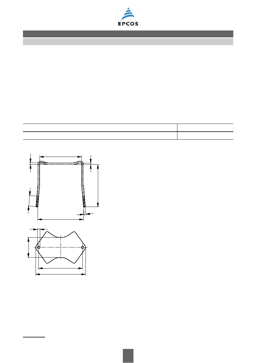
FPM0020-4-E
2.54
35.56
60.96
16
9
55.88
1
8
¯1.6+0.15
75.5 max.
48.5
25.7+0.3
38.9 max.
¯29 max.
33
1.4
1.5
48 max.
5.7
0.3
_
1.2 x 0.6
Marking of solder pin 1
Hole arrangement
View in mounting direction
¯3.5+0.2
0.5
_
0.3
_
2.54
B65685
Accessories
PM 62/49
4
09/06
Please read Cautions and warnings and
Important notes at the end of this document.
Mounting assembly
For chassis mounting
1)
or printed circuit boards
The set comprises a yoke and a base plate
Fixing nuts M3 and washers are supplied
Yoke
Material: Brass clamping yoke (
2.6 mm) with thread
Base plate
Material: Aluminum (0.6 mm)
Ordering code
Complete mounting assembly including nuts and washers
B65685A2000X000
FPM0009-T
59,8+0,3
2
59
1
_
15
64,8+1
M3
69 0,2
_
60,96±0,1
_
27,5
0,2
¯2,6
¯3,5+0,15
1) On a chassis the coil former must be mounted with its solder pins upward.
B65685
Accessories
PM 62/49

5
09/06
Ferrites and accessories
Cautions and warnings
Mechanical stress and mounting
Ferrite cores have to meet mechanical requirements during assembling and for a growing number
of applications. Since ferrites are ceramic materials one has to be aware of the special behavior
under mechanical load.
As valid for any ceramic material, ferrite cores are brittle and sensitive to any shock, fast changing
or tensile load. Especially high cooling rates under ultrasonic cleaning and high static or cyclic loads
can cause cracks or failure of the ferrite cores.
For detailed information see Data Book 2007, chapter "General ≠ Definitions, 8.1".
Effects of core combination on A
L
value
Stresses in the core affect not only the mechanical but also the magnetic properties. It is apparent
that the initial permeability is dependent on the stress state of the core. The higher the stresses are
in the core, the lower is the value for the initial permeability. Thus the embedding medium should
have the greatest possible elasticity.
For detailed information see Data Book 2007, chapter "General ≠ Definitions, 8.2".
Heating up
Ferrites can run hot during operation at higher flux densities and higher frequencies.
NiZn-materials
The magnetic properties of NiZn-materials can change irreversible in high magnetic fields.
Processing notes
≠ The start of the winding process should be soft. Else the flanges may be destroid.
≠ To strong winding forces may blast the flanges or squeeze the tube that the cores can no more
be mount.
≠ To long soldering time at high temperature (>300 ∞C) may effect coplanarity or pin arrangement.
≠ Not following the processing notes for soldering of the J-leg terminals may cause solderability
problems at the transformer because of pollution with Sn oxyd of the tin bath or burned insulation
of the wire. For detailed information see Data Book 2007, chapter "Processing notes, 2.2".
≠ The dimensions of the hole arrangement have fixed values and should be understood as a
recommendation for drilling the printed circuit board. For dimensioning the pins, the group of
holes can only be seen under certain conditions, as they fit into the given hole arrangement. To
avoid problems when mounting the transformer, the manufacturing tolerances for positioning the
customers' drilling process must be considered by increasing the hole diameter.