
Data Sheet
Data Sheet
Date:
September 2006
EPCOS AG 2006. Reproduction, publication and dissemination of this data sheet and the
information contained therein without EPCOS' prior express consent is prohibited.
Ferrites and accessories
EFD 15/8/5
Core and accessories
Series/Type:
B66413, B66414

2
09/06
Please read Cautions and warnings and
Important notes at the end of this document.
E core with flattened, lower center leg
for especially flat transformer design
For DC/DC converters
Delivery mode: single units
Magnetic characteristics (per set)
l/A = 2.27 mm
≠1
l
e
= 34 mm
A
e
= 15 mm
2
A
min
= 12.2 mm
2
V
e
= 510 mm
3
Approx. weight 2.8 g/set
Ungapped
Gapped
The A
L
value in the table applies to a core set comprising one ungapped core (dimension g = 0) and
one gapped core (dimension g > 0).
Calculation factors (for formulas, see "E cores: general information")
Validity range:
K1, K2: 0.10 mm < s < 1.00 mm
K3, K4: 30 nH < A
L
< 280 nH
Material
A
L
value
nH
µ
e
P
V
W/set
Ordering code
N49
600 +30/≠20%
1080
< 0.11 ( 50 mT, 500 kHz, 100 ∞C)
B66413G0000X149
N87
780 +30/≠20%
1400
< 0.28 (200 mT, 100 kHz, 100 ∞C)
B66413G0000X187
N97
820 +30/≠20%
1480
< 0.23 (200 mT, 100 kHz, 100 ∞C)
B66413G0000X197
Material
A
L
value
nH
µ
e
g
approx. mm
Ordering code
N87
100
±10%
180
0.17
B66413U0100K187
160
±15%
288
0.08
B66413U0160L187
Material
Relationship between
air gap ≠ A
L
value
Calculation of saturation current
K1 (25 ∞C)
K2 (25 ∞C)
K3 (25 ∞C)
K4 (25 ∞C)
K3 (100 ∞C)
K4 (100 ∞C)
N87
29.7
≠ 0.676
44.2
≠ 0.796
33.2
≠ 0.873
FEK0417-2
4,65±0,15
11±0,35
5,3±0,15
g
15±0,4
2,4±0,1
0,2±0,1
7,5±0,15
5,5±0,2
B66413
Core
EFD 15/8/5

3
09/06
Please read Cautions and warnings and
Important notes at the end of this document.
Coil former
Material:
GFR thermosetting plastic (UL 94 V-0, insulation class to IEC 60085:
H max.operating temperature 180 ∞C), color code black
Sumikon PM 9630
Æ
[E41429 (M)], SUMITOMO BAKELITE CO LTD
Solderability: to IEC 60068-2-20, test Ta, method 1 (aging 3): 235 ∞C, 2 s
Resistance to soldering heat: to IEC 60068-2-20, test Tb, method 1B: 350 ∞C, 3.5 s
Winding:
see Data Book 2007, chapter "Processing notes, 2.1"
Squared pins.
Yoke
Material:
Stainless spring steel (0.25 mm)
Coil former
Yoke
Coil former
Ordering code
Sections
A
N
mm
2
l
N
mm
A
R
value
µ
Pins
1
15.5
35.9
79.7
8
B66414W1008D001
Yoke (ordering code per piece, 2 are required)
B66414B2000X000
FEK0271-J
4,4
15,6
13,6 min.
1
4,8 max.
1
5.55+0.15
8.3 max.
3.5±0.2
1.7
0.45
2.55
7.5
_
0.2
0.15
0.1
15±0.2
Pin 1 marking
10.55
_
8
7
1
6.95
2
_
16.5±0.2
5
6
4
3
8.85 min.
0.15
1.6
_
FEK0418-A-E
4
0.2
Mounting holes
1
11.25
10.4
_
3.75
8
13.75
4
¯1+0.1
5
B66414
Accessories
EFD 15/8/5
4
09/06
Please read Cautions and warnings and
Important notes at the end of this document.
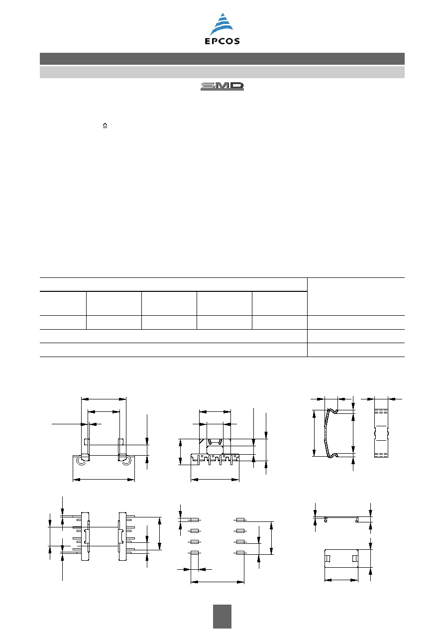
SMD coil former with J terminals
Material:
GFR liquid crystal polymer (UL 94 V-0, insulation class to IEC 60085:
F max. operating temperature 155 ∞C), color code black
Vectra C 130 [E83005 (M)], TICONA
Solderability: to IEC 60068-2-58, test Td, method 6 (Group 3): 245 ∞C, 3 s
Resistance to soldering heat: to IEC 60068-2-58, test Td, method 6 (Group 3): 255 ∞C, 10 s
permissible soldering temperature for wire-wrap connection on coil former: 400 ∞C, 1 s
Winding:
see Data Book 2007, chapter "Processing notes, 2.1"
Yoke
Material:
Stainless spring steel (0.25 mm)
Mounting:
Preferred assembly direction from the top
Cover plate
For marking and improved processing on assembly machines.
See under coil former for material and resistance to soldering heat.
Coil former
Yoke
Coil former
Ordering code
Sections
A
N
mm
2
l
N
mm
A
R
value
µ
Terminals
1
18.1
35.1
66.7
8
B66414B6008T001
Yoke (ordering code per piece, 2 are required)
B66414B2000X000
Cover plate
B66414A7000X000
FEK0187-Y
12,8±0,1
6,6±0,1
1,8±0,1
Abdeckplatte
0,5 max.
FEK0469-J-E
5.5+0.2
7.7±0.15
2.6+0.15
Recommended
PCB layout
17.7
11.25
3.75
0.55±0.05
0.6±0.05
2.5
11.25
3.75
1.2
5
6
7
8
1
2
3
4
0.25
15
_
0.2
_
10.4
0.5±0.05
0.2
_
3.45
0.3
_
20.8
_
10.6 0.2
7.3
0.1
_
_
16 0.2
0.2
_
6.4
Cover plate
FEK0271-J
4,4
15,6
13,6 min.
1
4,8 max.
1
B66414
Accessories
EFD 15/8/5

5
09/06
Ferrites and accessories
Cautions and warnings
Mechanical stress and mounting
Ferrite cores have to meet mechanical requirements during assembling and for a growing number
of applications. Since ferrites are ceramic materials one has to be aware of the special behavior
under mechanical load.
As valid for any ceramic material, ferrite cores are brittle and sensitive to any shock, fast changing
or tensile load. Especially high cooling rates under ultrasonic cleaning and high static or cyclic loads
can cause cracks or failure of the ferrite cores.
For detailed information see Data Book 2007, chapter "General ≠ Definitions, 8.1".
Effects of core combination on A
L
value
Stresses in the core affect not only the mechanical but also the magnetic properties. It is apparent
that the initial permeability is dependent on the stress state of the core. The higher the stresses are
in the core, the lower is the value for the initial permeability. Thus the embedding medium should
have the greatest possible elasticity.
For detailed information see Data Book 2007, chapter "General ≠ Definitions, 8.2".
Heating up
Ferrites can run hot during operation at higher flux densities and higher frequencies.
NiZn-materials
The magnetic properties of NiZn-materials can change irreversible in high magnetic fields.
Processing notes
≠ The start of the winding process should be soft. Else the flanges may be destroid.
≠ To strong winding forces may blast the flanges or squeeze the tube that the cores can no more
be mount.
≠ To long soldering time at high temperature (>300 ∞C) may effect coplanarity or pin arrangement.
≠ Not following the processing notes for soldering of the J-leg terminals may cause solderability
problems at the transformer because of pollution with Sn oxyd of the tin bath or burned insulation
of the wire. For detailed information see Data Book 2007, chapter "Processing notes, 2.2".
≠ The dimensions of the hole arrangement have fixed values and should be understood as a
recommendation for drilling the printed circuit board. For dimensioning the pins, the group of
holes can only be seen under certain conditions, as they fit into the given hole arrangement. To
avoid problems when mounting the transformer, the manufacturing tolerances for positioning the
customers' drilling process must be considered by increasing the hole diameter.