
Microwave Ceramics and Modules
Antenna
ISM2400 Vertical Embedded Antenna on big PCB
B69780T2457A000
Preliminary Datasheet
Customer: Standard
ISSUE DATE
24.11.03
ISSUE
P6
PUBLISHER
SAW MWC PD F
PAGE
1/5
Features
l Unbalanced 50 W, linearly polarized embedded antenna.
l Low loss LTCC substrate.
l SMD component with integrated feeding pad and soldering pad for positioning.
l Extra soldering terminal(s) can be added.
l Applications: WLAN, Bluetooth ...
Index
Page 2
∑ Component drawing
∑ Recommended footprint
Page 4
∑ Definition of the three main cut-planes
∑ Radiation patterns in the three main cut-planes
∑ Maximum ratings
Page 3
∑ Characteristics
∑ VSWR & SMITH chart diagrams
∑ Efficiency diagram
Page 5
∑ Processing information
∑ Soldering requirements
∑ Delivery mode
Microwave Ceramics and Modules
Antenna
ISM2400 Vertical Embedded Antenna on big PCB
B69780T2457A000
Preliminary Datasheet
Customer: Standard
ISSUE DATE
24.11.03
ISSUE
P6
PUBLISHER
SAW MWC PD F
PAGE
2/5
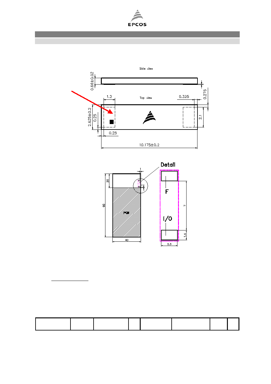
Component drawing
Recommended footprint
F :
Fixation pad. This pad is floating and should not be connected to any signal or
ground areas on the PCB.
I/O :
Should be connected to a 50 Ohms impedance line.
Standard Conditions:
-
FR4 Material (Permittivity 4.4, Thickness 0.8 mm)
-
No metallisation is allowed underneath the antenna area
* For customer specific needs, if the surrounding layout is different, additional SMD matching
components or more appropriate products should be advised by EPCOS.
I / O Pad
0.0
1
m
m
Microwave Ceramics and Modules
Antenna
ISM2400 Vertical Embedded Antenna on big PCB
B69780T2457A000
Preliminary Datasheet
Customer: Standard
ISSUE DATE
24.11.03
ISSUE
P6
PUBLISHER
SAW MWC PD F
PAGE
3/5
Characteristics
Min.
Typ.
Max.
Center frequency
1)
fc
2450
MHz
Bandwidth
B
100
MHz
Standing Wave Ratio
SWR
2.0
Impedance (unbalanced)
Z
50
W
Average Gain at fc (in all cuts)
2)
G
-4
-2
-1
dBi
Peak Gain at fc (in all cuts)
2)
pG
1
2
3
dBi
Efficiency
h
65
%
Polarization
P
Linear
Weight
W
0.075
g
Notes:
1)
Measured on FR4 90*40 mm≤ EPCOS standard PCB. The area under the antenna is free of
copper. See recommended Footprint.
2)
The values extracted are issued from the three main cuts of
the radiation pattern
f = 0, f = 90, q = -90. Measurement Accuracy ± 0,3 dB.
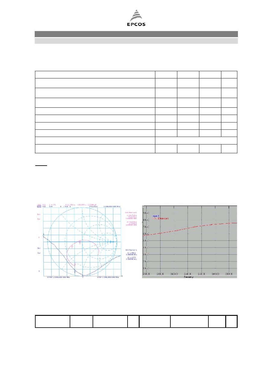
VSWR & Smith Diagrams
Efficiency in % vs Frequency

Microwave Ceramics and Modules
Antenna
ISM2400 Vertical Embedded Antenna on big PCB
B69780T2457A000
Preliminary Datasheet
Customer: Standard
ISSUE DATE
24.11.03
ISSUE
P6
PUBLISHER
SAW MWC PD F
PAGE
4/5
Definition of the three main cut-planes
Radiation Patterns in the three main cut-planes
Maximum ratings
IEC climatic category (IEC 68-1)
- 40 / +90 / 56
Operating temperature
Top
- 40 / + 90
∞C
f = 0
f = 90
q = -90
Microwave Ceramics and Modules
Antenna
ISM2400 Vertical Embedded Antenna on big PCB
B69780T2457A000
Preliminary Datasheet
Customer: Standard
ISSUE DATE
24.11.03
ISSUE
P6
PUBLISHER
SAW MWC PD F
PAGE
5/5
Processing information
l Wettability to IEC 68-2-58: ≥75% (after aging)
Soldering requirements
Soldering type
Reflow
Maximum soldering temperature
300 (max. 10 sec.)
∞C
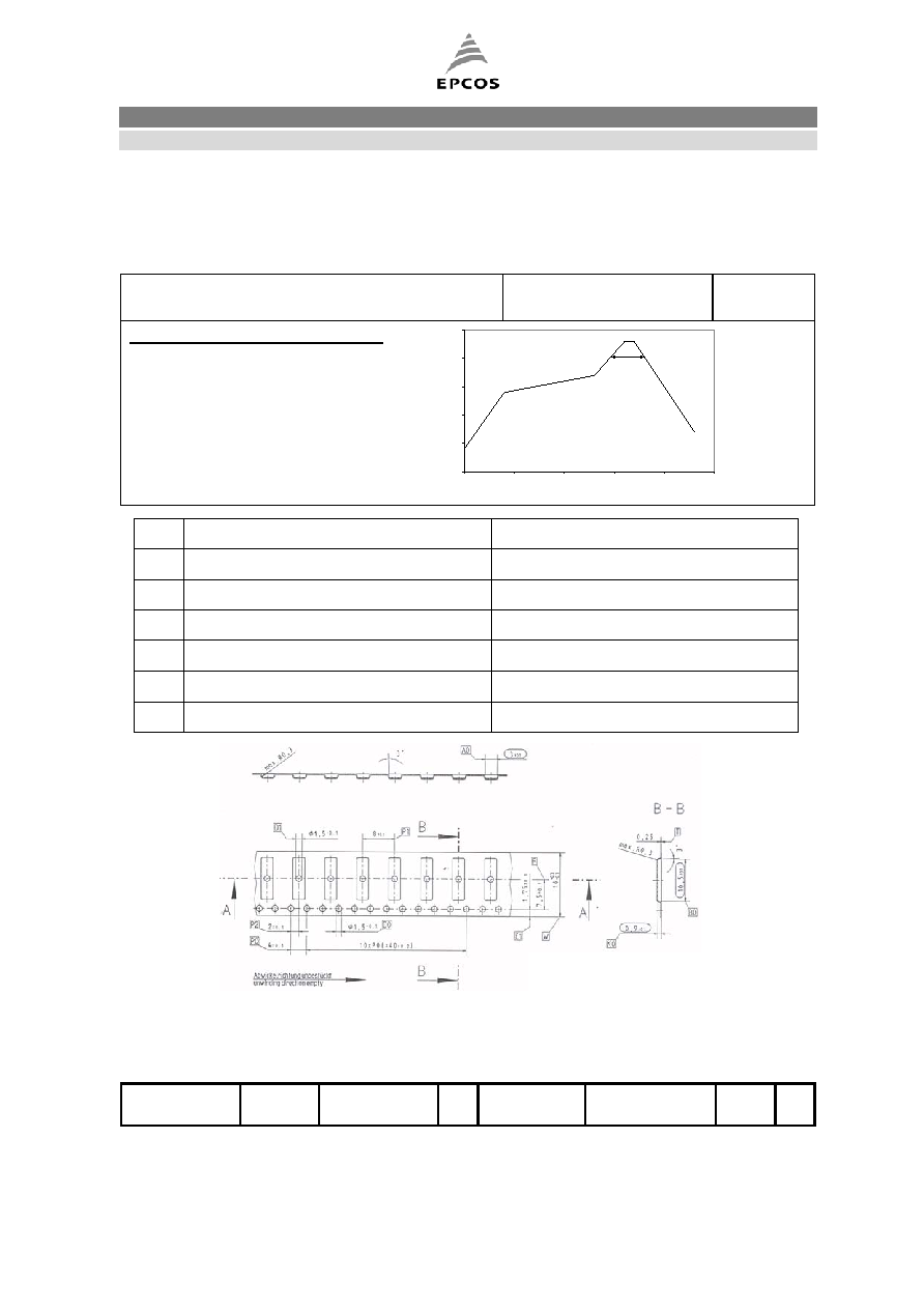
Recommended soldering conditions :
0
50
100
150
200
250
0
50
100
150
200
250
Time / s
T
e
mper
atur
e /C
1
2
3
5
6
4
Not to scale. For reference only.
Delivery mode
” EPCOS AG 2001. All Rights Reserved. Reproduction, publication and dissemination of this data sheet, enclosures hereto and the
information contained therein without EPCOS' prior express consent is prohibited.
The information contained in this data sheet describes the type of component and shall not be considered as guaranteed characteristics.
Purchase orders are subject to the General Conditions for the Supply of Products and Services of the Electrical and Electronics Industry
recommended by the ZVEI (German Electrical and Electronic Manufacturers' Association), unless otherwise agreed.
Ref
Parameter
Specification
1
Temperature gradient in preheating
Maximum 5 ∞C/s
2
Soak time (T=140...170 ∞C)
60...120 seconds
3
Temperature gradient in reflow
Maximum 3 ∞C/s
4
Time above 200∞C
30...45 seconds
5
Peak temperature in reflow
230...260
±5∞C for 10 seconds
6
Temperature gradient in cooling
Maximum -5 ∞C/s
7500 antennas per reel