 | –≠–ª–µ–∫—Ç—Ä–æ–Ω–Ω—ã–π –∫–æ–º–ø–æ–Ω–µ–Ω—Ç: S1M1W043 | –°–∫–∞—á–∞—Ç—å:  PDF PDF  ZIP ZIP |
Document Outline
- DESCRIPTION
- FEATURES
- BLOCK DIAGRAM
- PIN CONFIGURATION
- PIN DESCRIPTION
- ABSOLUTE MAXIMUM RATINGS
- DC RECOMMENDED OPERATING CONDITIONS
- ELECTRICAL CHARACTERISTICS
- FUNCTIONS
- PACKAGE DIMENSIONS

1
Rev.1.0
s
DESCRIPTION
The S1M1W043B0J7 is a 262,144 words x 16-bit asynchronous, random access memory on a monolithic CMOS
chip. Its very low standby power requirement makes it ideal for applications requiring non-volatile storage with
back-up batteries. The asynchronous and static nature of the memory requires no external clock and no refreshing
circuit. It is possible to control the data width by the data byte control. 3-state output allows easy expansion of
memory capacity. The temperature range of the S1M1W043B0J7 is from ≠40 to 85
∞
C, and it is suitable for the
industrial products.
s
FEATURES
q
Fast Access time ........................ 70ns (1.65V)
q
Low supply current ..................... LL Version
q
Completely static ........................ No clock required
q
Supply voltage ............................ 1.65V to 2.2V
q
3-state output with wired-OR capability
q
Non-volatile storage with back-up batteries
q
Package ..................................... S1M1W043B0J
PFBGA-48 pin (Plastic CSP)
s
BLOCK DIAGRAM
I/O Buffer
16
I/O1
I/O16
CS1
OE
WE
LB
UB
LB , UB
OE , WE
Control Logic
CS1,CS2,
Control
Logic
10
8
A0
A1
A2
A3
A4
A5
A6
A7
A8
A9
A10
A11
A12
A13
A14
A15
A16
A17
Address Buffer
Memory Cell Array
1024 x 256x 16
Column Gate
1024
256
256x 16
X Decoder
Y Decoder
CS2
4M-bit Static RAM
PF1195-01
S1M1W043B0J7
q
Super Low Voltage Operation and Low Current Consumption
q
Access Time 70ns (1.65V)
q
262,144 Words x 16-bit Asynchronous
q
Wide Temperature Range
Super Low Voltage
Operation
Products

S1M1W043B0J7
Rev.1.0
2
s
PIN CONFIGURATION
A
B
C
D
E
F
G
H
2
1
3
4
5
6
LB
I/O9
I/O10
V
SS
V
DD
I/O15
I/O16
NC
OE
UB
I/O11
I/O12
I/O13
I/O14
NC
A8
A0
A3
A5
A17
NC
A14
A12
A9
A1
A4
A6
A7
A16
A15
A13
A10
A2
CS1
I/O2
I/O4
I/O5
I/O6
WE
A11
CS2
I/O1
I/O3
V
DD
V
SS
I/O7
I/O8
NC
TFBGA-48 pin
Top view (Looking through part)
S1M1V083B0J
s
PIN DESCRIPTION
A0 to A17
WE
OE
CS1
CS2
LB
UB
I/O1 to 16
V
DD
V
SS
NC
Address Input
Write Enable
Output Enable
Chip Select1
Chip Select2
LOWER Byte Enable
UPPER Byte Enable
Data I/O
Power Supply (1.8V to 2.7V)
Power Supply (0V)
No connection
S1M1W043B0J7
3
Rev.1.0
s
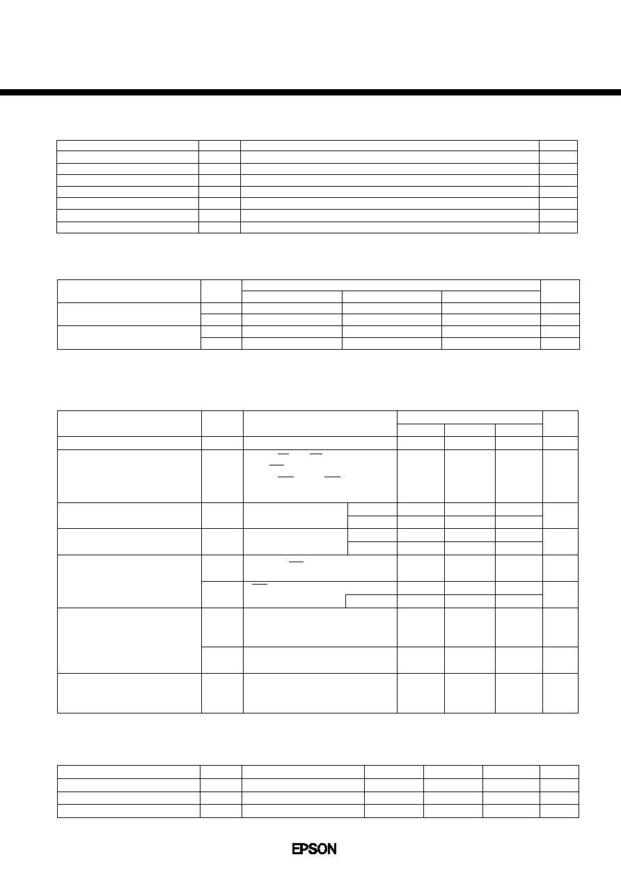
ABSOLUTE MAXIMUM RATINGS
Supply voltage
Input voltage
Input/Output voltage
Power dissipation
Operating temperature
Storage temperature
Soldering temperature and time
Parameter
V
DD
V
I
V
I/O
P
D
T
opr
T
stg
T
sol
Symbol
Ratings
Unit
≠ 0.3 to 2.7
≠ 0.3
*
to V
DD
+ 0.3
≠ 0.3
*
to V
DD
+ 0.3
0.5
≠ 40 to 85
≠ 65 to 150
260
∞
C, 10s (at lead)
(V
SS
=0V)
*
V
I
,V
I/O
(Min.) = ≠2.0V (when pulse width is less than 50ns)
V
V
V
W
∞
C
∞
C
≠
s
DC RECOMMENDED OPERATING CONDITIONS
Parameter
Supply voltage
Input voltege
Symbol
V
DD
V
SS
V
IH
V
IL
V
V
V
V
*
if pulse width is less than 50ns it is ≠ 2.0V
Min.
1.65
0.0
0.75V
DD
≠ 0.3
*
Typ.
1.8/2.0
0.0
≠
≠
Max.
2.2
0.0
V
DD
+0.3
0.3
Unit
V
DD
= 1.65 to 2.2V
(Ta = ≠40 to 85
∞
C)
s
ELECTRICAL CHARACTERISTICS
q
DC Electrical Characteristics
Parameter
Symbol
Conditions
Unit
Input leakage current
Standby supply current
Average operating current
Operating Supply Current
High level output voltage
I
LI
I
LO
V
OH
I
OH
Low level output voltage
V
OL
I
DDS
I
DDS1
I
DDA
I
DDA1
I
DDO
I
OL
µ
A
(V
SS
=0V, Ta = ≠40 to 85
∞
C)
V
DD
= 1.65 to 2.2V
V
I
= 0 to V
DD
LB and UB = V
IH
or
CS1 = V
IH
or CS2 = V
IL or
WE=V
IL
or OE = V
IH
,
V
I/O
= 0 to V
DD
CS1 = V
IH or
CS2= V
IL
Output leakage current
≠1.0
Min.
Max.
1.0
µ
A
≠1.0
1.0
mA
≠
0.5
10
1.0
µ
A
mA
≠
25
mA
≠
3.5
mA
≠
3.5
V
V
1.4
V
DD
≠0.2
≠
≠
≠
≠
0.4
0.2
*1 : Typical values are measured at Ta = 25
∞
C and V
DD
= 1.8V
V
I
= V
IL
or V
IH
I
I/O
= 0mA, t
cyc
= Min.
V
I
= V
IL
or V
IH
I
I/O
= 0mA, t
cyc
= 1
µ
s
V
I
= V
IL
or V
IH
I
I/O
= 0mA
≠0.5mA
≠100
µ
A
0.5mA
100
µ
A
Typ.
*1
≠
≠
17.8
2.1
2.1
≠
≠
≠
≠
≠
≠
0.5
≠
≠
CS1 = CS2
V
DD
≠ 0.2V
or CS2
0.2V
Ta
25
∞
C
q
Terminal Capacitance
(Ta = 25
∞
C, f = 1MHz)
Parameter
Symbol
Unit
Conditions
Address Capacitance
Input Capacitance
I/O Capacitance
C
ADD
C
I
C
I/O
V
ADD
= 0V
V
I
= 0V
V
I/O
= 0V
Max.
Min.
Typ.
Note : This parameter is made by the inspection data of sample, not of all products
≠
≠
≠
≠
≠
≠
8
8
10
pF
pF
pF
S1M1W043B0J7
Rev.1.0
4
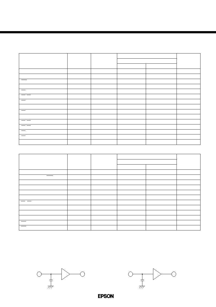
1TTL
I/O
C
L
*1 Test Conditions
1. Input pulse level : 0.3V to 0.8V
DD
(1.65V to 2.2V)
2. t
r
= t
f
= 5ns
3. Input and output timing reference levels :1/2V
DD
(1.65V to 2.2V)
4. Output load : C
L
=30pF (Includes Jig Capacitance)
*2 Test Conditions
1. Input pulse level : 0.3V to 0.8V
DD
(1.65V to 2.2V)
2. t
r
= t
f
= 5ns
3. Input timing reference levels :1/2V
DD
(1.65V to 2.2V)
4. Output timing reference levels :
±
200mV (The level changed from stable
output voltage level)
5. Output load :C
L
= 5pF (Includes Jig Capacitance)
q
AC Electrical Characteristics
r
Read Cycle
Unit
S1M1W043B0J7
1.65 to 2.2V
Min.
Max.
70
≠
≠
≠
≠
≠
5
5
≠
≠
0
≠
0
≠
5
≠
70
70
70
40
40
≠
≠
30
30
≠
30
≠
30
≠
Parameter
Symbol
Test
Conditions
(V
SS
= 0V, Ta = ≠40 to 85
∞
C)
Read cycle time
Address access time
CS1 access time
CS2 access time
OE access time
LB, UB access time
CS1 output set time
CS2 output set time
CS1 output floating
CS2 output floating
LB, UB output set time
LB, UB output floating
OE output set time
OE output floating
Output hold time
t
RC
t
ACC
t
ACS1
t
ACS2
t
OE
t
AB
t
CLZ1
t
CLZ2
t
CHZ1
t
CHZ2
t
BLZ
t
BHZ
t
OLZ
t
OHZ
t
OH
1
1
1
1
1
1
2
2
2
2
2
2
2
2
1
ns
ns
ns
ns
ns
ns
ns
ns
ns
ns
ns
ns
ns
ns
ns
r
Write Cycle
Unit
S1M1W043B0J7
1.65 to 2.2V
Min.
Max.
70
60
60
60
0
55
60
0
35
0
≠
5
≠
≠
≠
≠
≠
≠
≠
≠
≠
≠
30
≠
Parameter
Symbol
Test
Conditions
(V
SS
= 0V, Ta = ≠40 to 85
∞
C)
t
WC
t
CW1
t
CW2
t
AW
t
AS
t
WP
t
BW
t
WR
t
DW
t
DH
t
WHZ
t
OW
1
1
1
1
1
1
1
1
1
1
2
2
ns
ns
ns
ns
ns
ns
ns
ns
ns
ns
ns
ns
Write cycle time
Chip select time (CS1)
Chip select time (CS2)
Address enable time
Address setup time
Write pulse width
LB, UB select time
Address hold time
Data setup time
Data hold time
WE output floating
WE output set time
1TTL
I/O
C
L

S1M1W043B0J7
5
Rev.1.0
q
Timing Chart
CS1
Read Cycle
*1
A0 to 17
LB, UB
OE
I/O1 to 16
(Dout)
t
RC
t
ACC
t
BLZ
t
OE
t
OHZ
t
OLZ
Write Cycle 1 (CS1 Control)
*2, *3
t
AW
t
DW
t
WR
t
AS
t
DH
Write Cycle 3 (WE Control)
*3
Write Cycle 4 (UB, LB Control)
A0 to 17
CS1
LB, UB
WE
I/O1 to 16
(Dout)
(Din)
t
OH
High-Z
t
BW
t
CHZ1
t
CLZ1
CS2
CS2
t
WC
t
CW1
t
WP
t
DW
t
WR
t
AS
t
DH
A0 to 17
CS1
LB, UB
WE
I/O1 to 16
(Dout)
(Din)
High-Z
CS2
t
WC
t
CW1
t
WP
t
DW
t
BW
t
WR
t
AS
t
WHZ
t
OW
t
DH
A0 to 17
CS1
LB, UB
WE
I/O1 to 16
(Dout)
(Din)
t
CW2
Write Cycle 2 (CS2 Control)
*2, *3
t
AW
t
DW
t
WR
t
AS
t
DH
A0 to 17
CS1
LB, UB
WE
I/O1 to 16
(Dout)
(Din)
High-Z
t
BW
CS2
*3
CS2
t
CW2
t
WP
t
CW2
t
BW
t
CW1
t
WC
t
ACS1
t
WP
t
AB
t
ACS2
t
CLZ2
t
CW2
t
WC
t
CW1
t
BHZ
t
CHZ2
Note :
*
1
During read cycle time, W
__
E
_
is to be "High" level.
*
2 In write cycle time that is controlled by C
_
S
_
1
_
or CS2, output buffer is to be "Hi-Z" state even if O
_
E
_
is "Low" level.
*
3 When output buffer is in output state, be careful that do not input the opposite signals to the output data.
q
DATA RETENTION CHARACTERISTIC WITH LOW VOLTAGE POWER SUPPLY
Parameter
Symbol
Conditions
Min.
Typ.*
Max.
Unit
Data retention supply voltage
Data retention curren
Data hold time
Operation recovery time
V
DDR
I
DDR
t
CDR
t
R
V
µ
A
ns
ns
(V
SS
= 0V, Ta = ≠40 to 85
∞
C)
V
DDR
= 1.2V
CS1 = CS2
V
DD
≠ 0.2V or CS2
0.2V
* : Reference data at Ta=25
∞
C
1.0
≠
0
100
≠
0.25
≠
≠
2.2
5
≠
≠