
25≠40 W DC/DC Power Modules
48 V Input Series
∑ Single, dual and triple output
∑ 10.7 mm (0.42 in.), allows 0.8 in.
board spacing
∑ 1,500 V dc isolation voltage
∑ MTBF > 2 million hours at +75 ∞C
case temperature
∑ Complete, no extra filters or heatsinks
required
The 25≠40 watts PKE 4000 series hybrid DC/DC
power modules are especially designed for decentra-
lized 48/60 VDC power distribution systems with
distributed on-board DC/DC converters in
applications with high temperature and isolation
requirements.
By using a thickfilm technology, which provides a
high degree of integration as well as an efficient
thermal management and by utilizing a 300 kHz
switching frequency technology based on proprietary
drive & control chips, the highly reliable products
conform to the most stringent telecom and datacom
requirements in harsh environment applications.
Input to output isolation is as high as 1,500 Vdc and
mechanical ruggedness in conformance to IEC 68-2
≠ is close to the requirements for discrete
components. The converters can operate in free
convection with full output power at ambient
temperatures from ≠45 to +85∞C, making the
products ideal for the most de-manding temperature
requirements in both indoor and outdoor tele/
datacom applications.
These products are manufactured using highly
automated manufacturing lines with a world-class
quality commitment and a five-year warranty.
Ericsson Microelectronics AB has been an ISO 9001
certified supplier since 1991. For a complete product
program please reference the back cover.
E
PKE 4000 I

2
EN/LZT 146 26 R1A (Replaces EN/LZT 137 31 R1) © Ericsson Microelectronics AB, June 2000
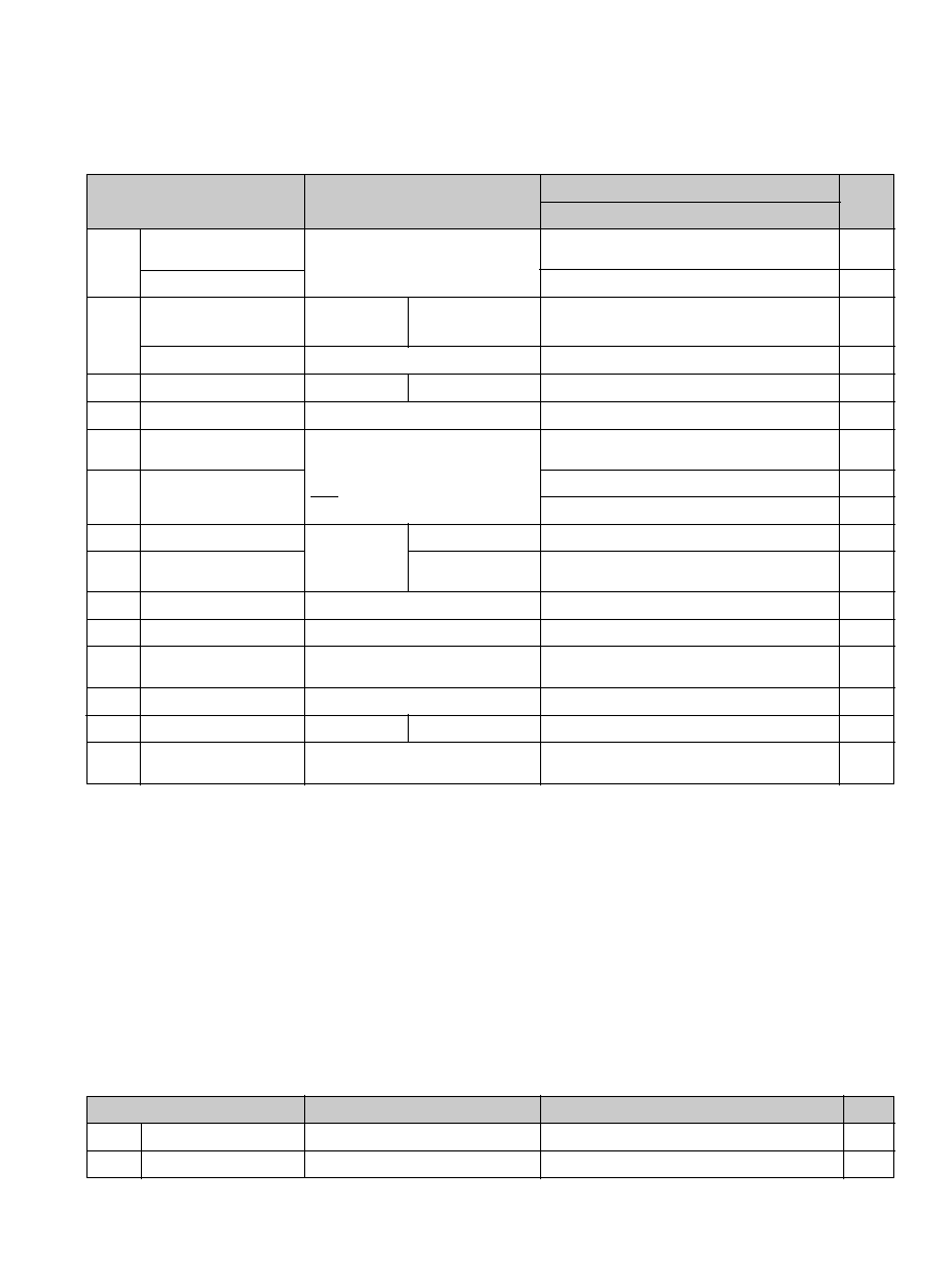
General
Absolute Maximum Ratings
Stress in excess of Absolute Maximum Ratings may cause permanent damage. Absolute Maximum Ratings, sometimes
referred to as no destruction limits, are normally tested with one parameter at a time exceeding the limits of Output
data or Electrical Characteristics. If exposed to stress above these limits, function and performance may degrade in an
unspecified manner.
Characteristics
min
max
Unit
T
C
Case temperature @ max output power
1)
+ 115
∞C
T
S
Storage temperature
≠ 55
+125
∞C
V
I
Input voltage
≠ 0.5
+ 75
V dc
V dc
V
ISO
V
RC
Remote control voltage pin 1
0
+ 5
V dc
V
adj
Output adjust voltage pin 10
0
V
O
V dc
Isolation voltage
(input to output test voltage)
1,500
V
tr
Transient input energy @ T
A
= +25 ∞C
1.3
Ws
Safety
The PKE 4000 I Series DC/DC power
modules are designed in accordance with
EN 60 950 Safety of information technology
equipment including electrical business equip-
ment, and certified by SEMKO.
The isolation is an operational insulation
in accordance with EN 60 950.
The PKE DC/DC power modules are re-
cognized by UL and meet the applicable
requirements in UL 1950 Safety of
information technology equipment, the
applicable Canadian safety requirements
and UL 1012 Standard for power supplies.
The DC/DC power module shall be
installed in an end-use equipment and is
intended to be supplied by isolated
secondary circuitry and shall be installed
in compliance with the requirements of
the ultimate application. When the
supply to the DC/DC power module meets
all the requirements for SELV (<60Vdc),
the output is considered to remain within
SELV limits (level 3). If connected to a
60 V DC power system, reinforced
insulation must be provided in the power
supply that isolates the input from the ac
mains. Single fault testing in the power
supply must be performed in combination
with the DC/DC power module to
demonstrate that the output meets the
requirement for SELV. One pole of the
input and one pole of the output is to be
grounded or both are to be kept floating.
The terminal pins are only intended for
connection to mating connectors of
internal wiring inside the end-use
equipment.
These DC/DC power modules may be used
in telephone equipment in accordance
with paragraph 34 A.1 of UL 1459
(Standard for Telephone Equipment,
second edition).
The isolation voltage is a galvanic
isolation and is verified in an electric
strength test. Test voltage between input
and output is 1,500 V dc.
The capacitor between input and output
has a value of 4.7 nF and the leakage
current is less than 1
mA @ 50 Vdc.
Flammability ratings of the terminal
support and internal plastic construction
details meet UL 94V-0.
Notes:
1)
Corresponding ambient temp. range (T
A
) at full output power is ≠ 45 to +85 ∞C. (Exceptions: PKE 4210 PI
= ≠ 45 to +75 ∞C, PKE 4411PI and PKE 4431 PI = ≠ 45 to +60 ∞C.)
2)
The input voltage range 38...72 V meets the requirements in the European Telecom Standard prETS 300 132-2
for Normal input voltage range in 48 V and 60 V DC power systems, ≠40.5...≠57.0 V and ≠50.0...≠72.0 V respec-
tively. At input voltages exceeding 72 V (abnormal voltage) the power loss will be higher than at normal input voltage
and T
C
must be limited to max +90∞C. Absolute max continuous input voltage is 75 V dc. Output characteristics will
be marginally affected at input voltages exceeding 72 V.
Input T
C
< T
C max
Characteristics
Conditions
min
typ
max
Unit
V
I
Input voltage range
2)
38
72
V
V
I off
Turn-off input voltage
(See Operating Information)
32
V
V
I on
Turn-on input voltage
(See Operating Information)
33
V
C
I
Input capacitance
1.8
mF
I
O
=0,T
C
= ≠0...+95∞C
15
30
mA
Equivalent inrush
current resistance
m
W
r
I rush
Quiscent drain current
I
d
30
Environmental Characteristics
Characteristics
Frequency
10...500 Hz
Amplitude
0.75 mm
Acceleration
10 g
Number of cycles
10 in each axis
Vibration
(Sinusoidal)
IEC 68-2-6 F
c
Test procedure & conditions
Peak acceleration
200 g
Shock duration
3 ms
Shock
(Half sinus)
IEC 68-2-27 E
a
Temperature
≠40∞C...+125∞C
Number of cycles
10
Temperature
change
IEC 68-2-14 N
a
Damp heat
IEC 68-2-3 C
a
Temperature
40∞C
Duration
56 days
Bump
(Half sinus)
IEC 68-2-29 E
b
Peak acceleration
40 g
Bump duration
6 ms
Number of bumps
1000 in 6 directions
Heat/humidity
IEC 68-2-3 C
a
with bias
Temperature
85∞C
Humidity
85% RH
Duration
500 hours

3
EN/LZT 146 26 R1A (Replaces EN/LZT 137 31 R1) © Ericsson Microelectronics AB, June 2000
Mechanical Data
Dimensions in mm (in)
Case
Blue anodized aluminum case with a
plastic bottom cover and with tin plated
brass pins.
Weight
Maximum 75 g (2.66 oz).
Connections
1
2
3
4
5
6
7
8
9
10
RC
Case
+In
≠In
Aux
NC/≠ Out 2/≠ Out 3
NC/+Out 2
≠Out1/Rtn
+Out 1
V
adj
Pin
Designation
Function
Remote Control. To turn-on and turn-off the output.
Connected to bottom cover.
Positive input.
Negative input.
Auxillary.
Not Connected in singles. Negative output 2 in duals.
Negative output 3 in triples
Not Connected in singles. Positive output 2 in duals and
triples.
Negative output1 in singles and duals. Return in triples.
Positive output 1 in all models.
Output voltage adjust.
Foot print Component side
5
EN/LZT 146 26 R1A (Replaces EN/LZT 137 31 R1) © Ericsson Microelectronics AB, June 2000
PKE 4210 PI
T
C
= 0...+95∞C, V
I
= 38 ...72V unless otherwise specified.
Characteristics
Conditions
Unit
min
typ
max
Efficiency
h
Power dissipation
P
d
Miscellaneous
75
78
%
7.1
8.3
W
I
O
= I
O max
, V
I
= 50 V, T
C
= +25∞C
I
O
= I
O max
, V
I
= 50 V, T
C
= +25∞C
0
7.6
A
Characteristics
Conditions
Output 1
min
typ
max
Unit
Output voltage initial
setting and accuracy
T
C
= +25 ∞C, I
O
= 7.6 A, V
I
= 50 V
V
Oi
Output voltage
tolerance band
V
O
Idling voltage
I
O
= 25 mA
Load regulation
I
O
= 0.1 ...1.0 ◊ I
O max
, V
I
= 50 V
t
tr
Load transient voltage
V
tr
Ramp-up time
t
r
Start-up time
t
s
0.1 ...0.9 ◊ V
O
From V
I
connection
to V
O
= 0.9 ◊ V
Oi
Output current
I
O
Max output power
2)
P
O max
Current limiting
threshold
I
lim
T
C
< T
C max
Output ripple
20 Hz ...5 MHz
Supply voltage
rejection (ac)
SVR
f = 100 Hz sine wave, 1 V
p-p
, V
I
= 50 V
(SVR = 20 log (1 V
p-p
/V
O p-p
))
Line regulation
I
O
= I
O max
Load transient
recovery time
3.28
3.30
3.32
V
4.0
V
mV
40
mV
≠480
mV
270
mV
15
ms
30
ms
25
W
102
%
70
90
mV
p-p
V
O ac
50
dB
50
m
s
I
O
= I
O max
Long term drift
included
Output
I
O
= 0.1 ...1.0 ◊I
O max
V
I
= 38...72 V
40
Output adjust range
1)
3.14
3.47
V
I
O
= 0.1 ... 1.0 ◊ I
O max
, V
I
= 50 V
load step = 0.5 ◊ I
Omax
I
O
=
0.1...1.0 ◊ I
O max
3.20
3.42
V
1)
See Operating Information.
2)
See Typical Characteristics, Power derating.
I
sc
Short curcuit current
1)
A
di
dt
£0.1A/ms
