
DC/DC power module
12V/ 0.65A / 7.8W
∑ SMD and through hole versions
with ultra-low component height
8.0 mm (0.315 in.)
∑ 81% efficiency at full load
∑ 1,500 Vdc isolation at full load
∑ Switching frequency synchronization
∑ MTTF >10 million hours at +50∞C
case temperature
∑ Low EMI
PKF 5713 I
E
The MacroDensTM 7.8W PKF 5713 I true component
level on-board DC/DC power modules are intended as
distributed power sources in decentralized power
systems with input voltages ranging from 18-75 VDC.
They are optimized for an operational ambient
temperature range in compliance with present and
future application needs, including non temperature
controlled environments.
The mechanical design offers the choice of surface
mount or through-hole versions, delivered in ready-
to-use tubes, trays or tape & reel package, and
compatibility with semi and fully aqueous cleaning
processes.
For mechanical and other information please refer to the
PKF series General information data sheet.
2
EN/LZT 146 127 R1A © Ericsson Microelectronics AB, December 2001
1)
The input voltage range 18...72 V dc meets
the European Telecom Standard prETS
300 132-2 Nominal input voltage range
in 48 V and 60 V dc power systems,
≠ 40.5...≠57.0 V and ≠50.0... ≠ 72.0 V
respectively. Absolute max continuous input
voltage is 75 Vdc.
2)
The power module will operate down to
£ 35V, when VI decreases, but will turn on to
at VI
£ 36V, when VI increases
(see also Operating information).
Stress in excess of Absolute Maximum
Ratings may cause permanent damage.
Absolute Maximum Ratings, sometimes
referred to as no destruction limits, are
normally tested with one parameter at a
time exceeding the limits of Output data
or Electrical Characteristics. If exposed to
stress above these limits, function and
performance may degrade in an unspecified
manner.
Absolute Maximum Ratings
Input T
C
< T
Cmax
unless otherwise specified
Characteristics
max
Unit
mW
mW
Input stand-by power
P
RC
Conditions
min
typ
V
I
Input voltage range
1)
72
V
18
V
Ioff
Turn-off input voltage
16.0
V
15.0
(See typical characteristics)
V
Ion
Turn-on input voltage
17.4
V
17.9
(See typical characteristics)
C
I
Input capacitance
1.4
mF
(V
I
= 27V)
(V
I
= 53 V)
413
400
I
O
= 0, T
C
= ≠ 30...+ 90 ∞C
P
Ii
Input idling power
T
C
= ≠ 30...+ 90 ∞C
RC connected to pin 17
(V
I
= 27V)
(V
I
= 53 V)
17
66
NOTES:
Characteristics
Unit
Isolation voltage
(input to output test voltage)
V
ISO
T
C
Case temperature at full output power
≠45
min
max
+100
∞C
T
S
Storage temperature
≠55
+125
∞C
V
I
Continuous input voltage
1)
≠0.5
+75
V dc
1,500
V dc
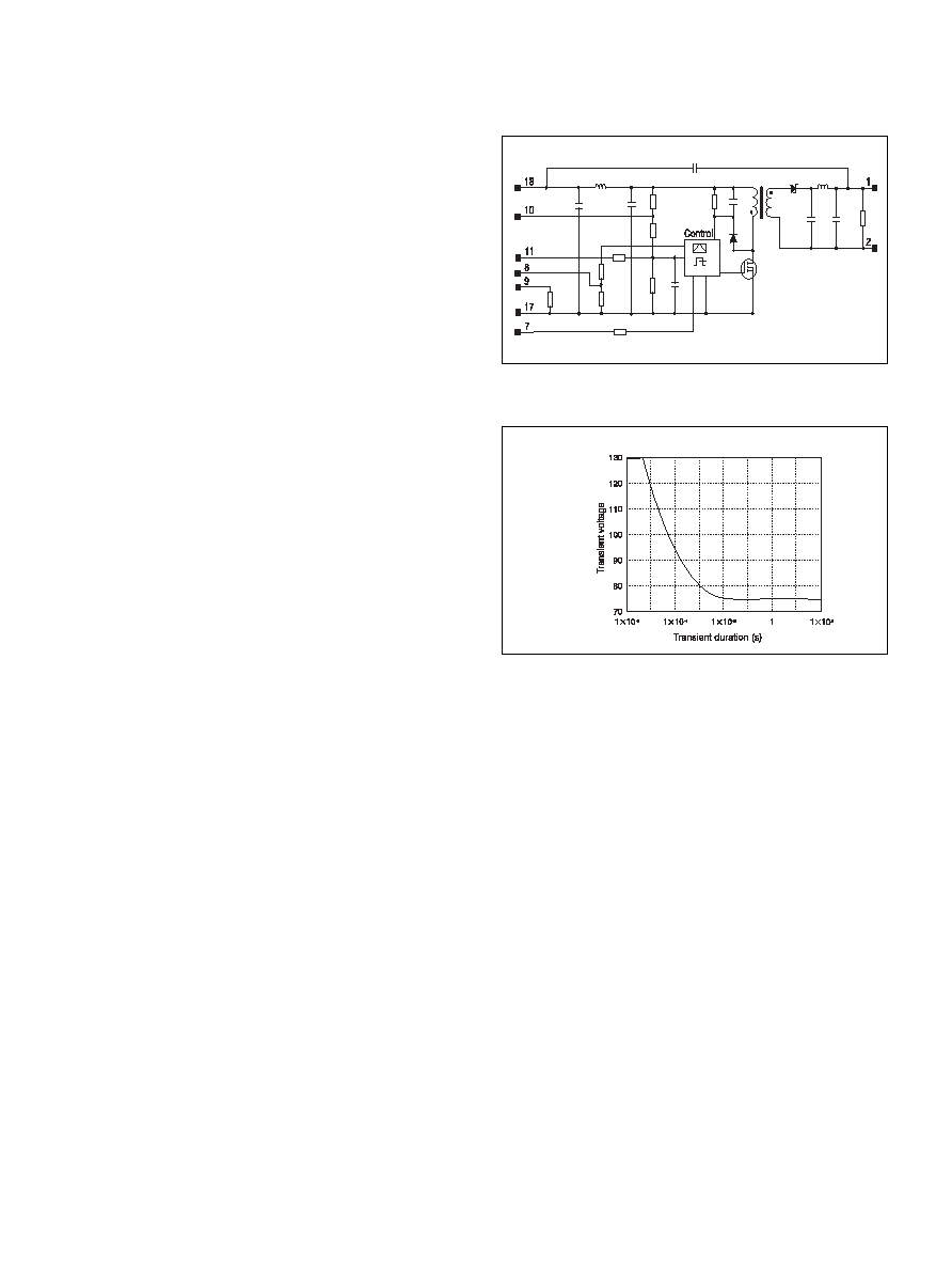
W
tr
Transient input energy
0.01
Ws
V
RC
Remote control voltage pin 10,11 ref. to pin 17.
+ 16
V dc
≠5
V
adj
Output adjust voltage pin 8, 9 ref. to pin 17.
+ 40
V dc
≠5
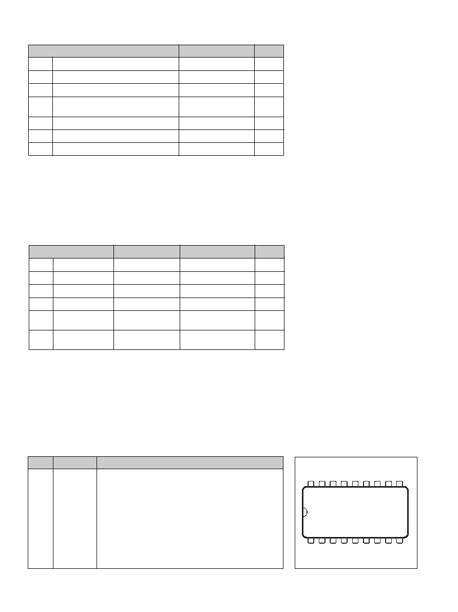
Connections
Pin
Designation
Function
1
Out 1
Output 1(+).
2
Rtn
Output return.
3-6
N C
Not connected. Galvanically Isolated from input pins.
7
Sync
Synchronization input.
8
V
adj
Output voltage adjust.
9
NOR
Connection of Nominal Output voltage Resistor.
10
TOA
Turn-on/off input voltage adjust.
11
RC
Remote control and turn-on/off input voltage adjust.
12≠16
N C
Not connected. Galvanically isolated from input pins.
17
≠In
Negative input.
18
+In
Positive input.
18 17 16 15 14 13 12 11 10
1 2 3 4 5 6 7 8 9
3
EN/LZT 146 127 R1A © Ericsson Microelectronics AB, December 2001
The PKF 5713 I DC/DC power module is designed in accordance
with EN 60 950, Safety of information technology equipment including
electrical business equipment. The PKF power modules are recognized by
UL and meet the applicable requirements in UL 1950 Safety of
information technology equipment, the applicable Canadian safety
requirements and UL 1012 Standard for power supplies.
The DC/DC power module shall be installed in an end-use
equipment and considerations should be given to measuring the
case temperature to comply with T
Cmax
when in operation.
Abnormal component tests are conducted with the input protected
by an external 15 A fuse. The need for repeating these tests in the
end-use appliance shall be considered if installed in a circuit having
higher rated devices.
When the supply to the DC/DC power module meets all the
requirements for SELV (<60Vdc), the output is considered to remain
within SELV limits (level 3). The isolation is an operational
insulation in accordance with EN 60 950.
The DC/DC power module is intended to be supplied by isolated
secondary circuitry and shall be installed in compliance with the
requirements of the ultimate application. If they are connected to
a 60 V DC system reinforced insulation must be provided in the
power supply that isolates the input from the mains. Single fault
testing in the power supply must be performed in combination with
the DC/DC power module to demonstrate that the output meets the
requirement for SELV. One pole of the input and one pole of the
output is to be grounded or both are to be kept floating. The
terminal pins are only intended for connection to mating connectors
of internal wiring inside the end-use equipment.
These DC/DC power modules may be used in telephone equipment
in accordance with paragraph 34 A.1 of UL 1459 (Standard for
Telephone Equipment, second edition).
The galvanic isolation is verified in an electric strength test. Test
voltage (V
ISO
) between input and output is 1,500 Vdc for 60 s. In
production the test duration may be decreased to 1 s.
The capacitor between input and output has a value of 1 nF and the
leakage current is less than 1µA @ 53 Vdc.
The case is designed in non-conductive epoxy. Its flammability
rating meets UL 94V-0. The oxygen index is 34%.
Single voltage pulse at +25∞C ambient temperature.
Electrical Data
Fundamental circuit diagram, Single output
Transient input voltage
Safety

4
EN/LZT 146 127 R1A © Ericsson Microelectronics AB, December 2001
T
C
= ≠30...+95 ∞C, V
I
= 18 ..72 V and pin 8 connected to pin 9.
Output
2.2
Characteristics
Conditions
Unit
min
typ
max
P
d
Power dissipation
Miscellaneous
%
Efficiency
h
I
O
= 0.65 A
78
81
V
I
= 27 V
V
I
= 53 V
V
I
= 27 V
V
I
= 53 V
80
81
2.0
W
0
0.65
A
Characteristics
Conditions
Output 1
min
typ
max
Unit
Output voltage initial
setting and accuracy
V
Oi
Output voltage
tolerance band
V
O
Idling voltage
I
O
= 0 A
Load regulation
I
O
= 0.065...0.65 A V
I
= 27 V
t
tr
Load transient voltage
V
tr
Temperature coefficient
2)
T
coeff
t
r
Start-up time
t
s
I
O
Max output power
2)
P
Omax
Current limiting
threshold
I
lim
T
C
<T
Cmax
, V
O
= 10 V
Short circuit current
I
sc
V
O
= 0.2...0.5 V, T
C
=+25∞C
20 Hz...5 MHz
Line regulation
I
O
=0,65 A
Load transient
recovery time
11.94
12.00
12.06
V
12.9
V
30
221
mV
+300
mV
≠300
mV
+1.6
mV/∞C
3.9
ms
7.2
ms
7.8
W
0.70
1.1
A
1.3
A
20
50
mV
p-p
80
dB
mV
50
ms
0.6 ...50 MHz
11.60
12.60
V
Long term drift
included
I
O
= 0.065...0,65 A
V
I
= 18...36 V
Output adjust range
1)
9.98
14.2
V
I
O
= 0.0.65...0.65 A V
I
= 27 V
load step =0.325A
60
dB
1)
See also Operating Information.
2)
See Typical Characteristics.
T
C
= +25∞C, I
O
= 0.5 A, V
I
= 27 V
Ramp-up time
Output current
I
O
= 0.65 A
Output ripple & noise
V
Oac
f = 100 Hz sine wave, 1V
p-p
, V
I
= 27 V
(SVR = 20 log (1 V
p-p
/V
Op-p
))
I
O
= 0.065...0.65 A V
I
= 27 V
From V
I
connection to V
O
= 0.9 ◊V
Oi
I
O
= 0.065...0.65 A, 0.1...0.9◊V
O
, V
I
= 27 V
I
O
= 0.65 A, T
C
=+40...+90∫C
SVR
Supply voltage rejection (ac)
V
I
= 50...72 V
10
mV
Calculated value

5
EN/LZT 146 127 R1A © Ericsson Microelectronics AB, December 2001
Output characteristic (typ)
Power derating
Temperature coefficient
Turn-on/turn-off input voltage
Efficiency (typ)
@ T
A
= +25∞C
-30,0
32,5
95,0
15,0
15,5
16,0
16,5
17,0
17,5
18,0
18,5
19,0
Turn-on
Turn-off
Turn-on/Tur-off voltage
Case temperature (C)
Dynamic load response (typ) @ +25∞C
-40
100
11,5
12,0
12,5
Output voltage (V)
Case temperature ∞(C)
EMC Specifications
During EMC measurements the PKF power module is
measured directly.
The fundamental switching frequency is 510 kHz ±5%
at I
O
= 0.065-0.65A
Test Conditions: V
I
= 53 V, I
O
= 0.65A at room temperature
Conducted EMI (input teminals)
External Filter (class B)
Required external input filter in order to meet class B in EN
55022, CISPR 22 and FCC part 15J.
PKF 5713 without filter
L1 = 51µH ( Recommended part: Siemens B82790-S0513 )
L2 = 10µH
C1, C2, C3 = 0.68 µF
C4 = 22µF
C5, C6 = 10nF
+
-
Supply
voltage
L1
C2
C3
C6
C5
C4
C1
L2
pin 18
pin 17
I
O
step=
0.325-0.65-0.325A
0.2 ms/div
The output voltage
deviation is
determined by the
load transient (dI/
dt)
Load change:
dI/dt
ª4 A/ms
200 mV/div
2 A/div
38
38V
38V
0
2
4
6
8
-40
-30
+80
+90
+100
+110
+120
Case temperature (∞C)
Max output power (W)
-50
Typical Characteristics
Load current (A)
Efficiency (%)
19,2 V
75 V
0
0.2
0.4
0.6
0.8
1.0
60
70
80
90
0.004
0.203
0.403
0.603
0.803
1.003
1.203
11.0
11.4
11.8
12.2
12.6
13.0
Load current (A)
Output Voltage (V)