 | –≠–ª–µ–∫—Ç—Ä–æ–Ω–Ω—ã–π –∫–æ–º–ø–æ–Ω–µ–Ω—Ç: PTF10007 | –°–∫–∞—á–∞—Ç—å:  PDF PDF  ZIP ZIP |

e
1
PTF 10007
35 Watts, 1.0 GHz
GOLDMOS
Æ
Field Effect Transistor
0
10
20
30
40
50
0
1
2
3
Input Power (Watts)
Ou
tp
u
t
Po
we
r
0
20
40
60
80
100
Efficiency
V
DD
= 28 V
I
DQ
= 300 m A
f = 960 MHz
Typical Output Pow er & Efficiency
vs. Input Pow er
Output Pow er (W)
Ef f iciency (%)
Package
20222
Description
The PTF 10007 is a 35 Watt GOLDMOS FET intended for large
signal amplifier applications to 1.0 GHz. It operates at 55% efficiency
and 13.5 dB of gain. Nitride surface passivation and gold
metallization ensure excellent device lifetime and reliability.
∑
Performance at 960 MHz, 28 Volts
- Output Power = 35 Watts
- Power Gain = 13.5 dB Typ
- Efficiency = 55% Typ
∑
Full Gold Metallization
∑
Silicon Nitride Passivated
∑
Back Side Common Source
∑
100% lot traceability
∑
Available in Package 20235 as PTF 10052
Maximum Ratings
Parameter
Symbol
Value
Unit
Drain-Source Voltage
V
DSS
60
Vdc
Gate-Source Voltage
V
GS
±20
Vdc
Operating Junction Temperature
T
J
200
∞C
Total Device Dissipation at Tflange = 25∞C
P
D
120
Watts
Above 25∞C derate by
0.7
W/∞C
Storage Temperature Range
T
STG
≠40 to +150
∞C
Thermal Resistance (Tflange = 70∞C)
R
q
JC
1.4
∞C/W
Package
20235
10007
A-1234569723
10052
A-1234569999

2
PTF 10007
e
Electrical Characteristics
(100% Tested)
Characteristic
Conditions
Symbol
Min
Typ
Max
Units
Drain-Source Breakdown Voltage
V
GS
= 0 V, I
D
= 5 mA
V
(BR)DSS
65
70
--
Volts
Drain-Source Leakage Current
V
DS
= 28 V, V
GS
= 0 V
I
DSS
--
--
1.0
mA
Gate Threshold Voltage
V
DS
= 10 V, I
D
= 75 mA
V
GS(th)
3.0
--
5.0
Volts
Forward Transconductance
V
DS
= 10 V, I
D
= 3 A
g
fs
--
2.8
--
Siemens
RF Specifications
(100% Tested)
Characteristic
Symbol
Min
Typ
Max
Units
Gain
(V
DD
= 28 V, P
OUT
= 35 W, I
DQ
= 300 mA, f = 960 MHz)
G
ps
12.0
13.5
--
dB
Power Output at 1 dB Compression
(V
DD
= 28 V, I
DQ
= 300 mA, f = 960 MHz)
P-1dB
35
--
--
Watts
Drain Efficiency
(V
DD
= 28 V, P
OUT
= 35 W, I
DQ
= 300 mA, f = 960 MHz)
h
50
55
--
%
Load Mismatch Tolerance
(V
DD
= 28 V, P
OUT
= 35 W, I
DQ
= 300 mA, f = 960 MHz--
Y
--
--
10:1
--
all phase angles at frequency of test)
Typical Performance
0
5
10
15
20
25
30
400
500
600
700
800
900
1000
Frequency (MHz)
Gai
n
20
30
40
50
60
70
Output Power & Effi
ci
ency
V
DD
= 28 V
I
DQ
= 300 mA
P
OUT
, Gain & Efficiency
(at P-1dB)
vs. Frequency
Efficiency (%)
Output Pow er (W)
G a in (d B )
Broadband Test Fixture Performance
4
8
12
16
20
925
930
935
940
945
950
955
960
Frequency (MHz)
Gai
n
0
10
20
30
40
50
60
V
DD
= 28 V
I
DQ
= 300 mA
P
OUT
= 35 W
Gain (dB)
Return Loss (dB)
Efficiency (%)
Effi
ci
en
cy
R
e
tur
n
Los
s
- 5
-15
-25
-35

3
PTF 10007
e
Typical Performance
Power Gain vs. Output Power
11
12
13
14
15
16
17
0.1
1.0
10.0
100.0
Output Power (Watts)
P
o
wer Gai
n
(
d
B)
V
DD
= 28 V
f = 960 MHz
I
DQ
= 150 mA
I
DQ
= 300 mA
I
DQ
= 75 mA
Intermodulation Distortion vs. Output Power
-60
-50
-40
-30
-20
-10
0
10
20
30
40
50
Output Power (Watts-PEP)
I
M
D (dBc
)
3rd
7th
5th
V
DD
= 28 V
I
DQ
= 300 m A
f
1
= 960.000 MHz
f
2
= 960.100 MHz
Output Power vs. Supply Voltage
30
35
40
45
22
24
26
28
30
32
34
Supply Voltage (Volts)
O
u
tp
u
t
Po
w
e
r (W
atts)
I
DQ
= 300 mA
P
OUT
= 5 W
f = 960 MHz
Capacitance vs. Supply Voltage
0
20
40
60
80
100
120
0
10
20
30
40
Supply Voltage (Volts)
Cds and Cgs (
pF)
0
5
10
15
20
25
30
35
40
Crss (pF)
C
gs
C
ds
C
rss
V
GS
=0 V
f = 1 MHz
Bias Voltage vs. Temperature
0.95
0.96
0.97
0.98
0.99
1.00
1.01
1.02
1.03
-20
30
80
130
Temp. (∞C)
B
i
as Voltage (V)
0.3
0.87
1.44
2.01
2.58
3.15
Voltage normalized to 1.0 V
Series show current (A)
4
PTF 10007
e
Typical Scattering Parameters
(V
DS
= 28 V, I
D
= 2.0 A)
f
S11
S21
S12
S22
(MHz)
Mag
Ang
Mag
Ang
Mag
Ang
Mag
Ang
400
0.948
-167
3.668
33
0.006
-37
0.858
-149
420
0.951
-168
3.403
32
0.005
-37
0.866
-150
440
0.955
-168
3.161
30
0.005
-37
0.877
-151
460
0.956
-168
2.943
29
0.005
-36
0.886
-152
480
0.957
-168
2.745
28
0.004
-38
0.892
-152
500
0.959
-168
2.575
27
0.004
-35
0.898
-153
520
0.960
-169
2.421
26
0.004
-34
0.903
-153
540
0.962
-169
2.282
25
0.004
-30
0.907
-154
560
0.963
-169
2.151
24
0.003
-29
0.911
-155
580
0.964
-169
2.024
22
0.003
-28
0.913
-155
600
0.964
-169
1.907
22
0.003
-23
0.919
-156
620
0.965
-169
1.806
21
0.002
-20
0.925
-156
640
0.967
-169
1.72
21
0.002
-13
0.929
-156
660
0.966
-170
1.636
20
0.002
-6
0.929
-157
680
0.967
-170
1.558
19
0.002
3
0.929
-157
700
0.967
-170
1.483
18
0.002
8
0.928
-157
720
0.968
-170
1.413
18
0.002
21
0.930
-158
740
0.968
-170
1.345
17
0.002
25
0.932
-158
760
0.967
-170
1.281
17
0.002
33
0.935
-159
780
0.966
-170
1.228
17
0.002
44
0.937
-159
800
0.967
-170
1.179
16
0.002
51
0.938
-159
820
0.968
-170
1.134
16
0.002
55
0.939
-159
840
0.967
-170
1.088
15
0.002
59
0.938
-160
860
0.967
-170
1.039
15
0.003
67
0.938
-160
880
0.967
-170
0.993
14
0.003
68
0.938
-160
900
0.966
-170
0.957
14
0.003
73
0.941
-161
920
0.966
-171
0.922
14
0.003
75
0.943
-161
940
0.966
-171
0.890
14
0.003
79
0.941
-161
960
0.966
-171
0.859
13
0.004
81
0.942
-161
980
0.966
-171
0.827
13
0.004
83
0.943
-161
1000
0.965
-171
0.794
12
0.004
86
0.942
-162
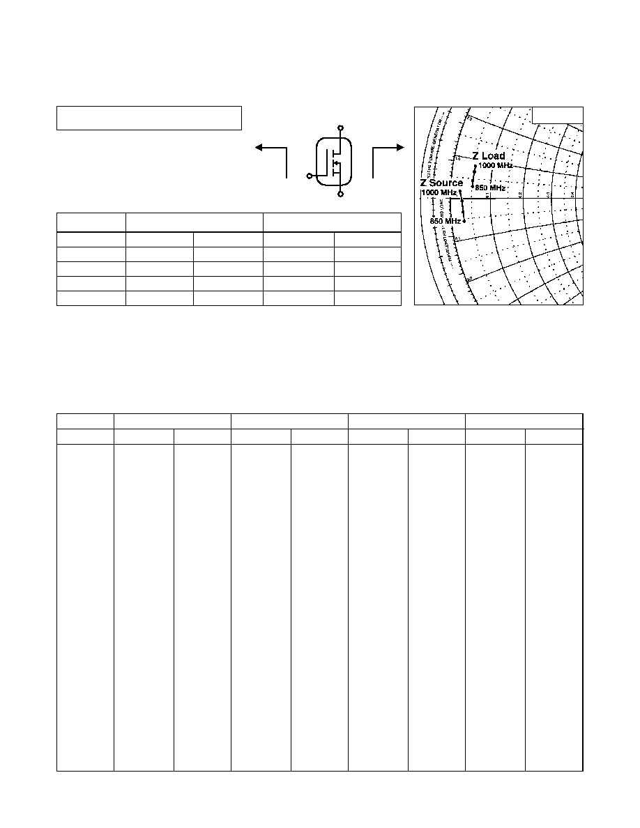
Impedance Data
(shown for fixed-tuned broadband circuit)
V
DD
= 28 V, P
OUT
= 35 W, I
DQ
= 300 mA
Z Source
Z Load
G
S
D
Z
0
= 50
W
Frequency
Z Source
W
Z Load
W
MHz
R
jX
R
jX
850
1.48
-2.80
2.60
1.55
900
1.45
-1.65
2.60
2.30
950
1.35
-0.30
2.68
3.40
1000
1.10
0.88
2.70
4.15

5
PTF 10007
e
Test Circuit Schematic for f = 960 MHz
DUT
PTF 10007
C1, C5
39 pF, Capacitor ATC 100 B
C2
7.5 pF, Capacitor ATC 100 B
C3
0.6≠6.0 pF, Trimmer Capacitor, Johanson, 5701-PC
C4
0.35≠3.5 pF, Trimmer Capacitor, Johanson, 5801-PC
C6, C8
51 pF, Capacitor ATC 100 B
C7, C9
0.1
m
F, 50 V, Capacitor, Digi-Key P4917-ND
C10
100
m
F, 50 V, Electrolytic Capacitor, Digi-Key P5276
L1
4 Turn, #20 AWG, .120" I.D.
R1
1 K, 1/4 W Resistor
R2
10 K, 1/4 W Resistor
l
1,
l
4
Microstrip 50
W
l
2
0.185
l
960 MHz
Microstrip 5.70
W
l
3
0.240
l
960 MHz
Microstrip 9.30
W
Circuit Board
.028" Dielectric Thickness,
e
r
= 4.0, AlliedSignal, G200, 2 oz. copper
Test Circuit
Parts Layout (not to scale)

6
PTF 10007
e
Package Mechanical Specifications
Package 20222
Ericsson Inc.
Microelectronics
Morgan Hill, CA 95037 USA
Specifications subject to change without notice.
LF
© 1997, 1998, 1999, 2000 Ericsson Inc.
EUS/KR 1522-PTF 10007 Uen Rev. C 11-09-00
1-877-GOLDMOS (465-3667) United States
+46 8 757 4700 International
e-mail: rfpower@ericsson.com
www.ericsson.com/rfpower
Artwork (not to scale)