 | –≠–ª–µ–∫—Ç—Ä–æ–Ω–Ω—ã–π –∫–æ–º–ø–æ–Ω–µ–Ω—Ç: 10TP581T | –°–∫–∞—á–∞—Ç—å:  PDF PDF  ZIP ZIP |

PRODUCT CATALOG
CAT. No.129E

SURGE ABSORBERS
SENSORS AND MODULES
THERMISTORS

3
THERMISTOR
POWER THERMISTOR
VRD
(TRANSIENT VOLTAGE SUPPRESSOR)
CRD
(CURRENT REGULATIVE DIODE)
ZENAMIC
(METAL OXIDE VARISTOR)
GAS TUBE ARRESTER
6
21
26
30
32
40
HIGH PRECISION SERIES
SMD SERIES
HIGH HEAT-RESISTANCE SERIES
DISK SERIES
SENSORS
NON-CONTACT SENSOR
4
THERMOPILE
NC SENSOR
D-TYPE SERIES
MARK SERIES
D2-TYPE SERIES
SMD SERIES
LEAD TYPE SERIES
LEAD TYPE SERIES
MELF TYPE SERIES
LEAD TYPE SERIES
M TYPE SERIES
SURGE ABSORBER UNIT SERIES
CERAMIC TUBE SERIES
GLASS TUBE SERIES
SA-01 SERIES

4
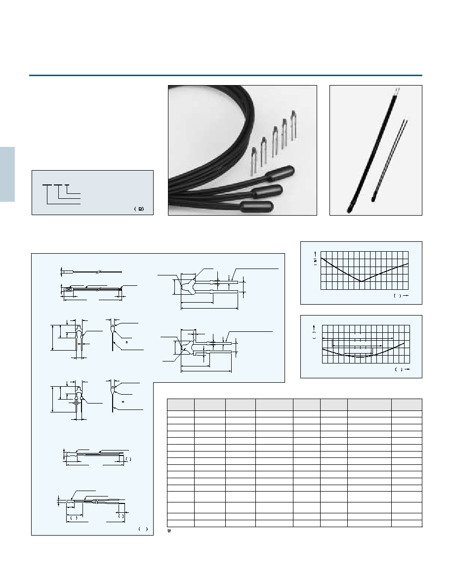
THERMOPILE
Dimensions
Ratings
Part number
Thermopile type Infrared sensor
utilizing own silicon micromachining
technology.
Applications:Eardrum thermometer
Microwave oven
Non contact temparature measurement
Part No.
15TP551T
15TP551N
10TP581T
type
TO5
TO18
Thermistor
Built-in
Built-in
8.2
0.05
3
4.5
3
0.8 0.1
1.8 max
45
0.8
A
1.56
0.01
9.4 max
2
2
1
1
4
4
3
3
3.8
0.05
0.45
0.03
10.3 max
A
TO5
4.65
0.05
(3.12)
(2.4)
0.7
A
1.05
0.01
5.6 max
2.4
A
TO18
0.1
0.4
0.45
0.05
0.03
3.2
0.3
0.1
6.6 max
(TOP VIEW)
(SIDE VIEW)
(BOTTOM VIEW)
5.08 0.2
1 0.2
1.35 0.2
2.2 0.1
13.2 0.5
Au plated
SENSOR
SURFACE
FILTER
SURFACE
R 0.3 max
R 0.5 max
OPTICAL
DISTANCE
2.54 0.2
13.2 0.5
2.95 0.2
1.25 0.2
0.55 0.2
SENSOR
SURFACE
FILTER
SURFACE
R 0.3 max
OPTICAL
DISTANCE
1
5
5
1 T
0 0
1
1
Parameters
Unit
Conditions
Value
15TP551
10TP581
Sensitive area
*
1
Responsivily
*
1
Output Voltage
*
2
Output Voltage
*
1
Temperature Coefficient
of Responsivily
Thermopile Resistans
Temperature Coefficient
of Thermopile Resistance
Johnson Noise Voltage
*
1
S/N Ratio
*
1
Noise Equivalent Power
*
1
Specific Detecivity
Time Constant
Operating Temperature range
Strage Temperature renge
Filter Range
Field of View
Insulation Rasistance
Sealing
*
3
Thermistor Resistance Value
*
3
Thermistor B-Value
*
3
Thermistor Rated Power
Test Condition
Blackbody Temperature
Sensor-Blackbody Distance
Sensor Temperature
Aperture size
: 500K
: 100mm
: 298K
: 12.7mm
*1
Test Condition
Blackbody Temperature
Sensor Temperature
: 310K
: 298K
*2
Built-in Type
*3
1.56 1.56
16 30%
490 30%
2.49 30%
0.01 0.02
55 30%
0.1
30
84.2
1.9
8.4 10
7
45
20 100
40 100
Cut on 5
45
500
1 10
9
100 3%
3435 0.7%
0.5
1.05 1.05
15 30%
200 30%
1.00 30%
0.02 0.02
65 30%
0.1
33
75.7
2.2
4.7 10
7
15
20 100
40 100
Cut on 5
50
500
1 10
9
100 3%
3435 0.7%
0.5
mm
2
V/ W
V
mV
% / C
k
% / C
nV/
dB
nW/ Hz
1/2
cm
∑
Hz
1/2
/ w
ms
C
C
m
deg.
M
Pa
∑
m
3
/ s
k
K
mW
Size of Absorbing Film
Reference
Johnson Noise r.m.s.,298K 1Hz Typical
Output Voltage/Johnson Noise, Typical
Typical
Typical
Typical
Standard
Incident Angle to Ahieve 50% Responsivity
Application of DC25V
Rated zero-power resistance Value at 25 C
at 25 C
Hz
Unit mm
THERMOPILE TYPE INFRARED SENSOR

5
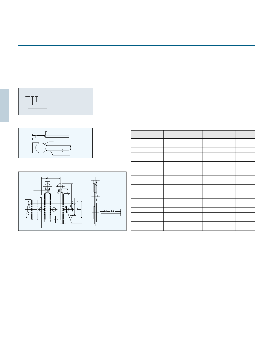
NC SENSOR
NC SENSOR is the remote temperature sensor
consisting of two precision thermistors.
1.Features
3. Dimensions
4.Specification
Parameters
F-type (for heat-roller)
M-type (for microwave ovens)
Performance
180 C 3 C
Conditions
Temperature
Accuracy
Blackbody Temperature : 180 C
Thermal Emissivity : 0.96
Temperature compensation : 100 C
Roller Size : 40mm
Testing Distance : 5mm
Resistor Connected : 33.0
Power Line Voltage : DC 5.000V
Operating
Temperature
Range
Temperature
Detecting
range
∑
Larger output in comparison with other IR sensors.
∑
Operating temperature of up 150
C.
∑
Minimum negative influence caused by a dew and/or
dust.
2.Applications
∑
Temperature measurment of the LBP and PPC heat-
roller.
∑
White goods such as microwave-ovens, air-conditioner,
refrigerator and so on.
∑
Any other measurement requiring the remote-sensing.
52.5
28
5
2
28
8
23
18
12
5
1
4
1
4.6
38
29.2
21.2
6
5.5
34.5
5
200 (120 300)
160 (120 300)
3
10
12.6
3.2
5.6
8
F-type
M-type
Unit mm
Unit mm
Performance
Conditions
Blackbody Temperature : 60 C
Thermal Emissivity : 0.995
Temperature compensation : 25 C
Resistor Connected : 68.0
Power Line Voltage : DC 5.000V
60 C 5 C
10 C 150 C
10 C 260 C
10 C 100 C
NON-CONTACT SENSOR (Infrared sensing temperature detector)

6
2.1
2.2
2.3
2.4
2.5
2.6
2.7
2.8
2.9
3.0
3.1
3.2
3.3
3.4
3.5
3.6
3.7
3.8
3.9
B:3350
B:3400
B:3650
1k
10k
100k
Resistance(
)
Temperature(1/ Tx10
3
)
THERMISTOR
"Thermistor" is the generic name given to
thermally sensitive resistors.
Negative temperature coefficient thermistor
is generally called as thermistor. Thermistor
is a semiconducting ceramic resistor
produced by sintering the materials at high
temperature and made mainly from metal
oxide.
Depending on the manufacturing method
and the structure, there are many shapes
and characteristics for various purposes
such as temperature measurement,
temperature compensation and etc.
The thermistor resistance values, unless
otherwise specified, are classified at a
standard temperature of 25 C.
B constant is calculated from the resistance
values at 25 C and 85 C.
The resistance of a temperature is solely a function
of its absolute temperature. Since electrical power
being dissipated within a temperature might heat
above its ambient temperature and thereby reduce
its resistance, it is necessary to test for resistance
with temperature. The resistance so measured is
called RT, which means the resistance at essentially
zero-power.
The mathematical expression which relates the
resistance and the absolute temperature of
a thermistor is as follows:
R
a
R
b
exp
B 1
T
1
1
T
2
B
T
2
R
a
T
1
Where:
is the resistance at absolute temperature
is the resistance at absolute temperature
R
b
T
2
B is a constant which depends on the
material of the thermistor
Unless otherwise specified,all values of B are
determined from measurements made at 25 C and
85 C.
The temperature coefficient of resistance
is expressed in the follow ing equation:
100 (%/ C)
Resistance -Temperature Characteristics
Dissipation factor
Thermal time constant
Dissipation factor ( ) is power in milliwatts
required to raise thermistor temperature 1 C.
Measured with thermistor suspended by its leads in
a specified environment.
t:Raise temperature( C)
t
P
(mW/ C)
P :Power(mW)
Thermal time constant (
a
) is the time required by a
thermistor to change 63% of the difference between
its initial and final temperature. Measured with
thermistor suspended by its leads in specified
environment.
95
87
63
a
2
a
3
a
5
a
Time (s)
(%)

7
JT THERMISTOR
JT thermistors feature ultra thinness of 500 m and
superior electrical insulation.
It is possible to use with safety in ambience that
might contact with electrodes.
Part number
103 JT- 025
Shape
Rated zero-power resistance
at 25 C 103
:
10k
JT the rmistor
Dimensions
A
3.6
0.5
5
1
2.0
0.5
0.5
0.035
0.17
0.02
1.8
0.1
Unit(mm)
0.5max.
Adhesive
lnsulation film
lnsulation film
Tin plated wires
42 Alloy leads
Slipped film
:
1 max.
Protruded adhesive
:
1 max.
Shape
Dimensions A
025
25
1
50
1
75
1
100
1
050
075
100
Specifications
Type
Resistance-Temperature
Temperature
( C)
Unit(k )
50
40
30
20
10
0
10
20
30
40
50
60
70
80
90
100
110
120
125
367.7
204.7
118.5
71.02
43.67
27.70
18.07
12.11
8.301
5.811
4.147
3.011
2.224
1.668
1.267
103JT
104JT
Part No.
R
25
*
1
B value
*
2
Dissipation factor
(mW/ C)
Thermal time
constant(s)
*
3
Operating temp.
range( C)
Rated power
at 25 C(mW)
103JT-
104JT-
10k
1%
100k
1%
3435K 1%
4390K 1%
0.7
0.7
5
5
3.5
3.5
50 90
50 125
9584
4572
2282
1191
647.2
365.0
212.5
127.7
78.88
50.03
32.51
21.61
14.66
10.13
7.135
5.111
3.720
2.746
2.371
*
1
R
25
: Rated zero-power resistance value at 25 C, 2% and 3% are also available.
*
2
B value : determined by rated zero-power resistance at 25 C and 85 C.
*
3
Time when thermistor temperature reaches 63.2% of the temperature difference. The value is measured in the air.
ULTIMATE THINNESS, JT THERMISTOR
500 m only
8
1.0
Tiebar cut
4.0 max.
2.54 0.25
8.5
1
17
1.5
Color code
Epoxy
0.5 Tin-Plated
42 Alloy
2.4 max.
2.4 max.
3.8 max.
15 max.
Marking
0.3sq
TPE lead wire
4.0 max.
5 max.
2.54 0.25
5 1
8.5
1
6
0.2
17
1.5
0.7
Tiebar cut
3.8 max.
Epoxy
Color code
0.5 Tin-Plated
42 Alloy
Soldered
600
20
0
AT-2
AT-11
AT-2SS
AT-2S
AT-3
AT THERMISTOR
The AT thermistor is a high-precision thermal
sensing device featuring extremely small
B-value tolerance and resistance.
When used as a temperature gauge, the AT
thermistor requires no adjustment between
the control circuit and the sensor.
This insures temperature precision of 0.3
C.
Temperature indicators and control instruments
are now available for use with the thermistor.
102 AT- 2
Shape
High-precision AT thermistor
Rated zero-power
Resistance at 25 C 102 : 1 k
Dimensions
Interchange precision
Part number
Specifications
Temperature
precision
C
2.5
2.0
1.5
1.0
0.5
0.5 C
0.7 C
1 C
102AT-2
202AT-2
502AT-2
103AT-2
203AT-2
503AT-2
104AT-2
103AT-3
102AT-11
202AT-11
502AT-11
103AT-11
1.0k
1%
2.0k
1%
5.0k
1%
10.0k
1%
20.0k
1%
50.0k
3%
100.0k
1%
10.0k
1%
1.0k
1%
2.0k
1%
5.0k
1%
10.0k
1%
3100K 1%
3182K 1%
3324K 1%
3435K 1%
4013K 1%
4060K 1%
4665K 1%
3435K 1%
3100K 1%
3182K 1%
3324K 1%
3435K 1%
2
2
2
2
2
2
2
2
3
3
3
3
15
15
15
15
15
15
15
15
75
75
75
75
10
10
10
10
10
10
10
10
15
15
15
15
50 90
50 90
50 110
50 110
50 110
50 110
50 110
50 110
50 90
50 90
50 105
50 105
Black
Red
Yellow
White
None
None
None
White
None
None
None
None
103AT-2S
103AT-2SS
103AT-4
Shape1
10.0k
1%
10.0k
1%
3435K 1%
3435K 1%
1
1
15
15
5
5
50 110
50 110
white
white
10.0k
1%
10.0k
1%
3435K 1%
3435K 1%
2
4
10
35
10
20
30 90
30 90
None
None
Part No
R
25
*1
B value
*2
Dissipation factor
(mW/ C)
Thermal time
constant (s)
*3
Operating temp.
range( C)
Color code
Rated power
at 25 C (mW)
*1 R
25
: Rated zero-power resistance value at 25 C.
*2 B value : determined by rated zero-power resistance at 25 C and 85 C.
*3 Time when thermistor temperature reaches 63.2% of the temperature difference. The value is measured in the air.
103AT-4
Shape2
Resistance tolerance
40
30 20 10
0
10 20 30 40 50 60 70 80 90 100
Resistance
tolerance
5
4
3
2
1
Ambient temperature C
40
30 20 10
0
10 20 30 40 50 60 70 80 90 100
Ambient temperature C
Unit mm
8max.
13max.
Epoxy
3
2.5max.
4max.
UL1685 AWG30
40 100
AT-4
Shape1
Shape2
30
5
100 225
Epoxy resin
HVFF 0.14sq
Color code
Epoxy
Epoxy
0.25t Tin plated 42 Alloy leads
3.0 4.0
2.9
3.3
2.54
0.25
17 1.5
8.5 1
(0.7
)
(0.35
)
Color code
0.25t Tin plated 42 Alloy leads
4.0 4.5
2.9
3.3
2.54
0.25
17 1.5
8.5 1
(0.7
)
(0.9
)
(0.6)
(0.35
)
Other resistance is also available, please ask.
AT-11,AT-2
AT-4
HIGH PRECISION THERMISTOR

9
AT-5 THERMISTOR
103 AT- 5-TP
Taping
Shape
High-precision AT thermistor
Rated zero-power
resistance at 25 C
Part number
Specifications
Part No
R
25
B value
Dissipation factor
(mW/ C)
Thermal time
constant (s)
Operating temp.
range( C)
Rated power
at 25 C (mW)
103AT-5
10.0k
1%
3435K 1%
2.5
15
10
50 110
Dimensions
Taping
AT-5
Resistance -Temperature
24.46
18.68
14.43
11.23
8.834
6.998
5.594
4.501
3.651
2.979
2.449
2.024
1.684
1.408
1.184
1.000
0.8486
11473
7781
5366
3728
2629
1864
1340
969.0
709.5
523.3
390.3
292.5
221.5
168.6
129.5
100.0
77.81
55.66
42.17
32.34
24.96
19.48
15.29
12.11
9.655
7.763
6.277
5.114
4.188
3.454
2.862
2.387
2.000
1.684
154.6
116.5
88.91
68.19
52.87
41.21
32.44
25.66
20.48
16.43
13.29
10.80
8.840
7.267
6.013
5.000
4.179
329.5
247.7
188.5
144.1
111.3
86.43
67.77
53.41
42.47
33.90
27.28
22.05
17.96
14.69
12.09
10.00
8.313
642.0
465.8
342.5
253.6
190.0
143.2
109.1
83.75
64.88
50.53
39.71
31.36
24.96
20.00
16.12
1632
1186
872.8
646.3
484.3
364.6
277.5
212.3
164.0
127.5
99.99
78.77
62.56
50.00
40.20
50
45
40
35
30
25
20
15
10
5
0
5
10
15
20
25
30
35
40
45
50
55
60
65
70
75
80
85
90
95
100
105
110
0.7229
0.6189
0.5316
0.4587
0.3967
0.3446
0.3000
0.2622
0.2285
0.1999
0.1751
0.1536
1.424
1.211
1.033
0.8854
0.7620
0.6587
0.5713
0.4975
0.4343
0.3807
0.3346
0.2949
3.508
2.961
2.509
2.137
1.826
1.567
1.350
1.168
1.014
0.8835
0.7722
0.6771
0.5961
0.5265
0.4654
0.4128
6.940
5.827
4.911
4.160
3.536
3.020
2.588
2.228
1.924
1.668
1.451
1.266
1.108
0.9731
0.8572
0.7576
13.06
10.65
8.716
7.181
5.941
4.943
4.127
3.464
2.916
2.468
2.096
1.788
1.530
1.315
1.134
0.9807
102AT
202AT
502AT
103AT
203AT
503AT
104AT
104AT
Temperature
( C)
Temperature
( C)
102AT
202AT
502AT
103AT
203AT
503AT
Unit(k )
32.48
26.43
21.59
17.75
14.64
12.15
10.13
8.482
7.129
6.022
5.105
4.345
3.712
3.185
2.741
2.369
60.94
48.10
38.13
30.44
24.42
19.72
15.99
13.05
10.68
8.796
7.271
6.041
5.037
4.220
3.546
2.994
Type
Type
1253
890.5
3168
2257
Other resistance is also available, please ask.
AT-5 thermistor is available in taping.
3 1
6 1
30 1
3.5
1
2.5
0.5
2.4
1
Epoxy
103AT
0.5 Tin plated CP leads
1
2
3
3
1
9.0
2.0
1.0
16.0
0.5
1
1.0 max.
3.5 1
6.35 1.3
12.7 1.0
12.7 0.3
1 max.
5
0.8
0.2
0.5 0.05
3 max.
4.0 0.3
12.5 min
9.0
0.75
0.5
18.0
0.5
2.4 1
2.0 max.
2.0 max.
1.5 max.
0.6
0.3
*1 R
25
: Rated zero-power resistance value at 25 C.
*2 B value : determined by rated zero-power resistance at 25 C and 85 C.
*3 Time when thermistor temperature reaches 63.2% of the temperature difference. The value is measured in the air.
AT-5

10
4 max.
4 max.
1.5 max.
1.6 max.
3 2
4 2
21 1
87 1
45 1
Resin(black)
Resin (ET-2 : light brown, ETB : black)
Soldered terminal
Resin
(0.17)
(0.25)
Enlarged view
Solder plated lead wires
(resin coated insulation)
Solder plated lead wires
(0.17)
(0.25)
Enlarged view
ET-2, ETB
ET-3
ET-1
Part number
Dimensions
ET THERMISTOR
The ET thermistor is smaller version of the AT thermistor.
Its fast response time and high reliability makes it
Particularly suitable for use in medical equipment
and thermometers. Manufactured by full-automated
production line, all ET thermistors have identical size and
that makes it possible to assemble sensors automatically.
503 ET 1
-
ET thermistor
Shape
Rated zero-power resistance at 25 C
503 : 50k
Specifications
Part No.
R
25
*
1
B value
*
2
Dissipation factor
(mW/ C)
Thermal time
constant (s)
*
3
Operating temp.
range ( C)
Rated power
at 25 C(mW)
402ET-1(2)
103ET-1(2)
303ET-1(2)
403ET-1(2)
413ET-1(2)
503ET-1(2)
593ET-1(2)
833ET-1(2)
104ET-1(2)
224ET-1(2)
234ET-1(2)
103ETB
503ET-3
4.0k
3%
10.0k
3%
30.0k
3%
40.0k
3%
41.0k
3%
50.0k
3%
59.0k
3%
83.0k
3%
100.0k
3%
226.0k
3%
232.0k
3%
10.0k
2%
50.0k
2%
3100K 1%
3250K 1%
3760K 1%
3525K 1%
3435K 1%
4055K 1%
3617K 1%
4013K 1%
4132K 1%
4021K 1%
4274K 1%
3435K 1%
4086K 1%
0.7
0.7
0.7
0.7
0.7
0.7
0.7
0.7
0.7
0.7
0.7
0.7
0.7
3.5
3.5
3.5
3.5
3.5
3.5
3.5
3.5
3.5
3.5
3.5
3.5
3.5
6
6
6
6
6
6
6
6
6
6
6
6
6
40 90
40 90
40 100
40 100
40 100
40 100
40 100
40 100
40 90
40 100
40 100
40 90
40 100
Temperature ( C)
Type
Resistance-Temperature
Unit (k )
Unit (k )
40
30
20
10
0
10
20
30
40
50
60
70
80
90
100
57.71
35.34
22.38
14.60
9.797
6.737
4.736
3.394
2.476
1.835
1.378
1.049
0.7997
0.6145
170.9
102.2
63.07
40.08
26.16
17.51
11.99
8.387
5.988
4.353
3.217
2.414
1.836
1.416
253.7
149.8
91.30
57.31
37.00
24.47
16.56
11.45
8.070
5.791
4.222
3.125
2.346
833.3
481.1
287.5
177.2
112.4
73.00
48.61
33.08
22.96
16.26
11.70
8.569
6.367
4.797
3.662
772.8
456.5
277.9
174.1
111.7
73.63
49.57
34.08
23.89
17.06
12.38
9.135
6.838
5.190
3.990
474.4
272.7
161.9
99.13
62.38
40.24
26.58
17.93
12.33
8.588
6.064
4.338
3.142
445.8
271.7
170.1
109.4
72.10
48.55
33.41
23.44
16.73
12.15
8.951
6.697
5.077
788.5
453.0
269.3
164.8
103.6
66.91
44.18
29.80
20.51
14.37
10.24
7.419
5.459
977.5
559.0
329.8
200.5
125.3
80.27
52.62
35.23
24.00
16.59
11.64
8.287
2116
1225
730.1
447.8
282.1
182.1
120.3
81.07
55.75
39.01
27.78
20.10
14.75
2515
1401
808.2
480.2
293.7
184.4
118.6
78.00
52.39
35.87
24.99
17.72
12.75
204.7
118.5
71.02
43.67
27.70
18.07
12.11
8.301
5.811
4.147
3.011
2.224
1.668
1.267
402ET
103ET
303ET
403ET
413ET
503ET
593ET
833ET
104ET
224ET
234ET
103ETB
Specifications for clinical thermo-meter
Temperature ( C)
Type
40.22
30.00
21.75
3953
67.04
50.00
36.25
3953
182.4
136.0
98.56
3958
184.5
135.0
95.87
4209
R
30
R
37
R
45
B
30/45
(K)
503ET
833ET
224ET
234ET
Unit (mm)
1602
855.0
1318
754.3
2664
1421
3325
1769
7005
3784
9046
4680
810.7
445.1
Epoxy resin (White)
Polyurethane-covered CP wire
0.16 Color:White
Soldered (Pb free)
100 2
3 1
5max.
1.6max.
*1 R
25
: Rated zero-power resistance value at 25 C.
*2 B value : determined by rated zero-power resistance at 25 C and 85 C.
*3 Time when thermistor temperature reaches 63.2% of the temperature difference. The value is measured in the air.

11
Part number
Dimensions
Taping
Package
Our newly developed
IT
thermistors are axial
leaded diode type packaged in high-density resin
mold and featured strength against various operating
environments.
We offer
IT
thermistor with 2% tolerance for a
resistance value of 25 C and 1% for B value.
IT
thermistors are the most appropriate device for
accurate temperature control below 100 C.
103 I T
IT thermistor
Rated zero-power resistance
at 25 C 103 : 10k
Mark
Reel
Ammopack (Zig-Zag)
Epoxy
0.6 Silver plated
CP wire
2.5
0.1
95
2
76
2
70
2
100
5
260
5
80
5
24
0.5
30
2
350
2
30
2
30
2
3
0.1
103 AA
Lot NO
103 : 10k
Unit (mm)
(mm)
Unit (mm)
Unit (mm)
2
5
6
1.2 max
0.5 max.
Minimum quantity : 5000 pcs/ reel
Minimum quantity : 2000 pcs/box
Label
52
182.1
93.35
49.85
27.75
16.02
9.541
5.876
3.728
2.431
1.623
303.4
155.6
83.09
46.25
26.70
15.90
9.793
6.214
4.051
2.705
367.7
204.7
118.5
71.02
43.67
27.70
18.07
12.11
8.301
5.811
1539
810.8
445.1
253.8
149.8
91.31
57.32
36.99
24.47
16.56
3135
1602
855.0
474.4
272.7
161.9
99.13
62.38
40.24
26.58
9584
4572
2282
1191
647.2
365.0
212.5
127.7
78.88
50.03
1026
540.5
296.7
169.2
99.85
60.87
38.21
24.66
16.31
11.04
Specifications
Part No.
R
25
*
1
B value
*
2
Dissipation factor
(mW/ C)
Thermal time
constant (s)
*
3
Operating temp.
range ( C)
Rated power
at 25 C (mW)
*
1 R
25
: Rated zero-power resistance value at 25 C, 1% and 3% are also available.
*
2 B value : determined by rated zero-power resistance at 25 C and 85 C.
*
3 Time when thermistor temperature reaches 63.2% of the temperature difference. The value is measured in the air.
302 I T
3.0k
2%
5.0k
2%
10.0k
2%
20.0k
2%
30.0k
2%
50.0k
2%
100.0k
2%
3860K 1%
3860K 1%
3435K 1%
3760K 1%
3760K 1%
4055K 1%
4390K 1%
3.6
3.6
3.6
3.6
3.6
3.6
3.6
13.5
13.5
13.5
13.5
13.5
13.5
13.5
18.0
18.0
18.0
18.0
18.0
18.0
18.0
50 125
50 125
50 100
50 125
50 125
50 125
50 125
Resistance-Temperature
50
40
30
20
10
0
10
20
30
40
Temperature
( C)
Temperature
( C)
1.109
0.7744
0.5513
0.4000
0.2951
0.2210
0.1680
0.1295
0.1142
50
60
70
80
90
100
110
120
125
1.849
1.291
0.9189
0.6667
0.4918
0.3683
0.2800
0.2158
0.1903
4.147
3.011
2.224
1.668
1.267
0.9753
7.632
5.380
3.861
2.815
2.083
1.564
1.190
0.9159
0.8067
11.45
8.070
5.792
4.223
3.125
2.346
1.785
1.374
1.210
17.93
12.33
8.588
6.064
4.338
3.142
2.302
1.705
1.472
32.51
21.61
14.66
10.13
7.135
5.111
3.720
2.746
2.371
Unit (k )
I T THERMISTOR
Unit
502 I T
103 I T
104 I T
503 I T
302 I T
502 I T
103 I T
203 I T
303 I T
503 I T
104 I T
302 I T
502 I T
203 I T
303 I T
503 I T
104 I T
103 I T
303 I T
203 I T
Type
Type
ACCURATE AXIAL TYPE THERMISTOR

12
1.6
0.15
2.65
0.2
3.80
0.15
0.02
0.05
1.1
0.15
0.6
103
Dimensions
Dimensions
Taping
Taping
42 Alloy
Epoxy resin
Mark
1.6
0.15
3.0
0.3
0.3
0.8
1.1
0.15
2.65
0.2
8.65
0.5
5.25
0.1
1.7
103
Mark
Epoxy resin
Solder plated
lead wires
42 Alloy
0.6
0.1
(0.1)
0.8
0.6
Unit (mm)
Part number
HT THERMISTOR
103 HT
Shape
Tolerance of R
25
Taping HTF only
Rated zero-power resistance at 25 C 103
: 10k
HT thermistors are entirely new type of thermistor
for surface mounting (by reflow soldering) and were
acquired from advanced technology.
Our HT thermistors are adapted metal electrodes
packaged in a resin mold, unlike conventional chip
thermistors, and can offer 2% tolerance for a
resistance value at 25 C.
HT series (SMD Thermistor) is not only compact-
surface mounting type but also highly accurate and
reliable.
182.1
93.35
49.85
27.75
16.02
9.541
5.876
3.728
2.431
1.623
303.4
155.6
83.09
46.25
26.70
15.90
9.793
6.214
4.051
2.705
367.7
204.7
118.5
71.02
43.67
27.70
18.07
12.11
8.301
5.811
1539
810.8
445.1
253.8
149.8
91.31
57.32
36.99
24.47
16.56
3135
1602
855.0
474.4
272.7
161.9
99.13
62.38
40.24
26.58
9584
4572
2282
1191
647.2
365.0
212.5
127.7
78.88
50.03
1026
540.5
296.7
169.2
99.85
60.87
38.21
24.66
16.31
11.04
Specifications
Part No.
R
25
*
1
B value
*
2
Dissipation factor
(mW/ C)
Thermal time
constant (s)
*
3
Operating temp.
range ( C)
Rated power
at 25 C (mW)
*
1
R
25
: Rated zero-power resistance value at 25 C, 1% and 3% are also available.
*
2
B value : determined by rated zero-power resistance at 25 C and 85 C.
*
3
Time when thermistor temperature reaches 63.2% of the temperature difference. The value is measured in the air.
302HT(F)
502HT(F)
103HT(F)
203HT(F)
303HT(F)
503HT(F)
104HT(F)
3.0k
2%
5.0k
2%
10.0k
2%
20.0k
2%
30.0k
2%
50.0k
2%
100.0k
2%
3860K 1%
3860K 1%
3435K 1%
3760K 1%
3760K 1%
4055K 1%
4390K 1%
1.0
1.0
1.0
1.0
1.0
1.0
1.0
8.0
8.0
8.0
8.0
8.0
8.0
8.0
5.0
5.0
5.0
5.0
5.0
5.0
5.0
50 125
50 125
50 100
50 125
50 125
50 125
50 125
Resistance-Temperature
50
40
30
20
10
0
10
20
30
40
Type
302HT
502HT
103HT
203HT
303HT
503HT
Type
302HT
502HT
103HT
203HT
303HT
503HT
104HT
Temperature
( C)
Temperature
( C)
1.109
0.7744
0.5513
0.4000
0.2951
0.2210
0.1680
0.1295
0.1142
50
60
70
80
90
100
110
120
125
1.849
1.291
0.9189
0.6667
0.4918
0.3683
0.2800
0.2158
0.1903
4.147
3.011
2.224
1.668
1.267
0.9753
7.632
5.380
3.861
2.815
2.083
1.564
1.190
0.9159
0.8067
11.45
8.070
5.792
4.223
3.125
2.346
1.785
1.374
1.210
17.93
12.33
8.588
6.064
4.338
3.142
2.302
1.705
1.472
32.51
21.61
14.66
10.13
7.135
5.111
3.720
2.746
2.371
Unit (k )
4.0
0.1
1.9
0.1
4.0
0.1
1.45
0.1
2.0
0.1
1.75
0.1
16.0
0.2
7.5
0.1
0.2
0.05
1.55
0.05
1.5
0.1
1.9
0.1
4.0
0.1
4.0
0.1
2.0
0.1
3.55
0.1
1.55
0.1
8.0
0.2
0.2
0.05
(1.45)
4.1
0.1
104HT
-TP
-
1P
: 1% 2P : 2%
HT
HTF
9.3
0.1
Minimum quantity:3000pcs/reel
0.2
0
SURFACE MOUNT TYPE THERMISTOR

13
0.44
0.03
0.5
0.1
0.15
0.05
1.0 0.1
0.22 0.03
0.22 0.03
Part number
Dimensions
FT THERMISTOR
The FT thermistors, the highly reliable thermistors, are
characterized by their fast response time, which was
made possible by the miniaturization of the thermistor
dimensions. FT thermistors are also heat-resistant type.
FT thermistors are the most excellent products of today
,
s
chip thermistors manufacturing.
364 FT
Thin film thermistor
Rated zero-power Resistance
at 25 C : 364k
Temperature
( C)
Resistance -Temperature
20
10
0
10
20
25
30
40
50
60
70
80
90
100
110
B=3370K
67.26
42.10
27.08
17.86
12.07
10.00
8.332
5.871
4.216
3.081
2.288
1.725
1.318
1.021
0.8003
B=3435K
70.34
43.55
27.71
18.11
12.12
10.00
8.299
5.804
4.139
3.006
2.220
1.666
1.269
0.9797
0.7662
B=3370K
336.3
210.5
135.4
89.31
60.33
50.00
41.66
29.36
21.08
15.40
11.44
8.623
6.592
5.105
4.002
B=3435K
351.9
217.7
138.5
90.48
60.58
50.00
41.50
29.03
20.70
15.04
11.11
8.331
6.344
4.898
3.829
B=3370K
2447
1532
985.4
650.0
439.1
363.9
303.2
213.7
153.4
112.1
83.25
62.76
47.98
37.15
29.12
103FT
503FT
364FT
P/N
Temperature
( C)
120
125
130
140
150
160
170
180
190
200
210
220
230
240
250
B=3370K
0.6345
0.5671
B=3435K
0.6064
0.5418
B=3370K
3.172
2.836
B=3435K
3.029
2.706
B=3370K
23.09
20.64
18.50
14.97
12.23
10.07
8.364
7.000
5.901
5.008
4.277
3.676
3.177
2.760
2.411
103FT
503FT
364FT
P/N
Specifications
Part No.
R
25
*
1
B value
*
2
Dissipation factor
(mW/ C)
Thermal time
constant (s)
*
3
Operating temp.
range ( C)
Rated power
at 25 C (mW)
*
1 R
25
: Rated zero-power resistance value at 25 C.
*
2 B value : determined by rated zero-power resistance at 25 C and 85 C.
*
3 Time when thermistor temperature reaches 63.2% of the temperature difference. The value is measured in the air.
103FT
103FT
503FT
503FT
364FT
10k
5%
10k
5%
50k
5%
50k
5%
364k
5%
3435K 1%
3370K 1%
3435K 1%
3370K 1%
3370K 1%
0.3
0.3
0.3
0.3
0.3
2.0
2.0
2.0
2.0
2.0
1.5
1.5
1.5
1.5
1.5
20 125
20 125
20 125
20 125
20 250
Unit (mm)
(0.5)
Glass
Unit (k )
Connect the FTs to the electrodes with using conductive epoxy resins.
The FTs cannot be soldered onto the electrodes.
THIN FILM TYPE THERMISTOR

14
SMD type chip
Chip thermistors are specially processed, highly
reliable thermistors.
They can be face-bonded to act as thermal
compensators for ICs and they are manufactured
in sizes down to 1 square mm, they can also be
used to detect temperature with relatively small
time constants.
Precautions
Dimensions
Reflow soldering profile
103 K T 2125T -
Rated zero-power resistance at 25 C 103:10k
Part number
Chip thermistor
1P: 1%,2P: 2%,3P: 3%
Dimension(EIAJ) 2125
Specifications
Part No.
R
25
*1
B value*
2
Dissipation factor
(mW/ C)
Thermal time
constant(s)*
3
Operating temp.
range( C)
Rated power
at 25 C(mW)
*1 R
25
: Rated zero-power resistance value at 25 C.
*2 B value : determined by rated zero-power resistance at 25 C and 85 C.
*3 Time when thermistor temperature reaches 63.2% of the temperature difference. The value is measured in the air.
Other resistance is available, please ask.
103KT2125T
103KT1608T
503KT1608T
104KT1608T
103KT1005T
10k
10k
50k
100k
10k
3435K 1%
3435K 1%
4055K 1%
4390K 1%
3435K 1%
1.0
0.9
0.9
0.9
0.7
7.5
5.0
5.0
5.0
2.2
5.0
4.5
4.5
4.5
3.5
40 125
40 125
40 125
40 125
40 125
Unit(mm)
1.5
(1.0 0.1)
1.65 0.2
4.0 0.1
4.0 0.1
2.0 0.05
3.5
0.05
1.75
0.1
8.0
0.3
1.5max.
(0.25max.)
( ):1608type
0.3max.
0.1
0
2.4
0.2
(1.85
0.1)
Taping (2125, 1608 type)
Do not expose the thermistors to high
soldering heat for more than specified time.
(260 C for not longer than 10s is
recommended)
Unit(mm)
L
L
1
L
1
W
Glass coating
Electrode
(Sn plated)
190 C 15 C
260 C 5 C
Temperature
Time
Soldering
Cooling
Preheat(air)
120s 30s
1 2
C/s
10s
max.
Minimum quantity:4000pcs/reel
Minimum quantity:10000pcs/reel
Unit(mm)
(1005 type)
T
EIA
0402
0603
0805
EIAJ
1005
1608
2125
L
1.00 0.15
1.60 0.15
2.00 0.20
W
0.50 0.10
0.80 0.15
1.25 0.20
T
0.6max.
0.95max.
1.2max.
L
1
0.15 0.30
0.20 0.50
0.20 0.50
2.0 0.05
0.66 0.03
0.9max
0.75 0.02
4.0 0.1
0.6 0.10
2.0 0.10
1.75
0.1
3.5
0.05
8.3 max
1.5
0.1
0
1.10
0.10
CHIP TYPE THERMISTOR

15
3 1
1.35
0.15
48 1
Glass
Nickel-plated
(0.15)
(0.18)
Part number
Time constant
Dimensions
GT THERMISTOR
GT thermistor is combined both superior feature of
BT thermistor and ET thermistor as fast response
time, high reliability, wide category temperature
range, high moisture proof, high accuracy and
reasonable price.
GT thermistor is made up of a high quality
thermistor element and the lead wire is connected to
the thermistor element by alloyed technology, and
glass coating for the thermistor element.
103 GT 1
-
GT thermistor
Shape
Rated zero-power resistance at 25 C
103
:
10k
100
95.0
86.5
80
63.2
60
40
20
0
0
2
4
6
8
10
12
(%)
Time (s)
in air
in silicone oil
Specifications
Part No.
R
25
*
1
B value
*
2
Dissipation factor
(mW/ C)
Thermal time
constant(s)
*
3
Operating temp.
range( C)
Rated power
at 25 C(mW)
*
1
R
25
: Rated zero-power resistance value at 25 C.
*
2
B value : determined by rated zero-power resistance at 25 C and 85 C.
*
3
Time when thermistor temperature reaches 63.2% of the temperature difference. The value is measured in the air. (silicone oil)
102GT-1
202GT-1
502GT-1
103GT-1
203GT-1
503GT-1
104GT-1
204GT-1
504GT-1
105GT-1
3305K 2%
3838K 2%
3964K 2%
4126K 2%
4282K 2%
4288K 2%
4267K 2%
4338K 2%
4526K 2%
4608K 2%
0.6
0.6
0.6
0.6
0.6
0.6
0.6
0.6
0.6
0.6
3
3
3
3
3
3
3
3
3
3
7(0.6)
7(0.6)
7(0.6)
7(0.6)
7(0.6)
7(0.6)
7(0.6)
7(0.6)
7(0.6)
7(0.6)
50 200
50 300
50 300
50 300
50 300
50 300
50 300
50 300
50 300
50 300
Resistance-Temperature
Temperature ( C)
Type
Unit (k )
102GT
202GT
502GT
103GT
203GT
503GT
104GT
204GT
504GT
105GT
50
40
30
20
10
0
10
20
30
40
50
60
70
80
90
100
110
120
130
140
150
160
170
180
190
200
210
220
230
240
250
260
270
280
290
300
32.57
18.48
10.84
6.594
4.144
2.675
1.773
1.203
0.8354
0.5918
0.4273
0.3141
0.2347
0.1782
0.1373
0.1072
111.3
61.34
33.69
18.79
10.82
6.424
3.939
2.489
1.618
1.080
0.7390
0.5170
0.3695
0.2693
0.1998
0.1507
0.1154
342.1
175.4
92.54
50.44
28.49
16.66
10.06
6.264
4.019
2.651
1.792
1.239
0.8753
0.6304
0.4624
0.3450
0.2614
0.2010
0.1566
0.1236
825.1
405.3
206.6
109.9
60.72
34.82
20.66
12.64
7.968
5.164
3.436
2.341
1.631
1.159
0.8391
0.6181
0.4626
0.3514
0.2706
0.2111
0.1666
0.1330
0.1073
1901
909.0
453.2
236.6
128.3
72.32
42.24
25.47
15.82
10.10
6.620
4.444
3.050
2.138
1.527
1.111
0.8209
0.6160
0.4686
0.3613
0.2820
0.2226
0.1777
0.1432
0.1166
4613
2199
1100
576.2
315.1
178.8
104.9
63.52
39.62
25.37
16.64
11.16
7.645
5.338
3.795
2.742
2.014
1.501
1.133
0.8662
0.6704
0.5247
0.4149
0.3314
0.2673
0.2174
0.1784
0.1475
0.1230
0.1032
8743
4218
2132
1127
620.0
353.7
208.6
126.8
79.36
50.96
33.49
22.51
15.44
10.80
7.686
5.556
4.082
3.043
2.298
1.758
1.360
1.064
0.8414
0.6714
0.5408
0.4393
0.3597
0.2969
0.2468
0.2065
0.1740
0.1475
0.1258
0.1079
0.09305
0.08065
8810
4436
2329
1272
720.3
421.8
254.6
158.2
100.8
65.85
43.99
29.98
20.82
14.71
10.57
7.720
5.720
4.296
3.269
2.516
1.958
1.539
1.222
0.9796
0.7919
0.6455
0.5303
0.4389
0.3658
0.3068
0.2591
0.2201
0.1881
0.1616
0.1396
12091
6268
3372
1880
1083
642.3
391.9
245.4
157.5
103.3
69.20
47.23
32.84
23.22
16.68
12.15
8.976
6.719
5.091
3.903
3.024
2.367
1.871
1.492
1.200
0.9726
0.7946
0.6539
0.5418
0.4519
0.3793
0.3203
0.2720
0.2323
6920
3833
2190
1289
780.9
485.2
309.0
201.2
133.6
90.53
62.49
43.90
31.34
22.69
16.65
12.39
9.330
7.107
5.472
4.255
3.339
2.644
2.113
1.702
1.382
1.131
0.9323
0.7735
0.6459
0.5424
0.4583
0.3894
Unit (mm)
1.0k
3%
2.0k
3%
5.0k
3%
10.0k
3%
20.0k
3%
50.0k
3%
100.0k
3%
200.0k
3%
500.0k
3%
1000.0k
3%
0.08483
0.06787
0.05488
0.04483
0.03697
0.03077
0.02584
0.02189
0.01869
0.01610
0.08973
0.07068
0.05638
0.04550
0.03715
0.03065
0.02556
0.02151
0.01826
0.09865
0.07967
0.06501
0.05358
0.04457
0.03741
0.03167
0.02703
0.02324
0.02014
0.01759
0.08741
0.07186
0.05960
0.04986
0.04204
0.03573
0.03059
0.02640
0.09573
0.07929
0.06620
0.05570
0.04722
0.04030
HIGH HEAT-RESISTANCE
AND HIGH SENSITIVE THERMISTOR

16
1.35max.
1.5max.
70 min.
Glass
Glass
Part number
Dimensions
BT THERMISTOR
The BT thermistor is a small thermal sensing device
providing high reliability, stable characteristics and a
wide operating range of 50 C to 300 C.
It is used in various applications including medical
apparatus, industrial equipment and home electric
appliances.
10 BT 5
-
Bead thermistor
Shape
Rated zero-power resistance at 25 C 10:10k
4.5max.
70 min.
3.5max.
0.225
Dumet leads
0.2
Dumet leads
Fig.2
(BT-6)
Fig.1
(BT-5)
Specifications
Port No.
R
25
*1
B value
*2
Dissipation factor
(mW/ C)
Thermal Time
constant(s)
*3
Operating temp.
range( C)
Rated power
at 25 C(mW)
*
1 R
25
: Rated zero-power resistance value at 25 C, 5% are also available.
*
2 B value : determined by rated zero-power resistance at 25 C and 85 C.
*
3 Time when thermistor temperature reaches 63.2% of the temperature difference. The value is measured in the air
1BT-5
2BT-5
5BT-5(6)
9BT-5(6)
10BT-5(6)
20BT-5(6)
30BT-5(6)
40BT-5(6)
100BT-5(6)
400BT-5(6)
500BT-5(6)
1.3MBT-5(6)
1.000k
10%
2.000k
10%
5.000k
10%
9.000k
10%
10.00k
10%
20.00k
10%
30.00k
10%
40.00k
10%
100.0k
10%
400.0k
10%
500.0k
10%
1300k
10%
3,250K
3%
3,420K
3%
3,450K
3%
3,470K
3%
3,250K
3%
3,330K
3%
3,450K
3%
3,550K
3%
3,750K
3%
4,050K
3%
3,760K
3%
4,380K
3%
0.5(0.4)
0.5(0.4)
0.5(0.4)
0.5(0.4)
0.5(0.4)
0.5(0.4)
0.5(0.4)
0.5(0.4)
0.5(0.4)
0.5(0.4)
0.5
0.5
4
12
4
12
4
12(3
8)
4
12(3
8)
4
12(3
8)
4
12(3
8)
4
12(3
8)
4
12(3
8)
4
12(3
8)
4
12(3
8)
4
12(3
8)
4
12(3
8)
50
150
50
300
50
300
50
300
50
300
50
300
50
300
50
300
50
300
50
300
50
300
50
150
2.5
2.5
2.5(2)
2.5(2)
2.5(2)
2.5(2)
2.5(2)
2.5(2)
2.5(2)
2.5(2)
2.5(2)
2.5(2)
Temperature ( C)
Type
Resistance-Temperature
50
40
30
20
10
0
10
20
25
30
40
50
60
70
80
90
100
110
120
130
140
150
160
170
180
190
200
210
220
230
240
250
260
270
280
290
300
29.87
17.33
10.35
6.374
4.038
2.629
1.755
1.200
1.000
0.8380
0.5973
0.4338
0.3205
0.2407
0.1834
0.1417
0.1110
0.08789
70.71
40.02
23.28
13.96
8.640
5.513
3.610
2.421
2.000
1.661
1.163
0.8311
0.6043
0.4468
0.3357
0.2559
0.1978
0.1547
0.1224
0.09789
0.07908
0.06450
35.44
21.84
13.87
9.057
6.060
5.000
4.148
2.898
2.065
1.497
1.104
0.8267
0.6280
0.4836
0.3771
0.2975
0.2373
0.1913
0.1556
0.1278
0.1058
0.08836
0.07432
0.06295
344.8
190.3
109.1
64.81
39.70
25.15
16.36
10.92
9.000
7.456
5.200
3.698
2.677
1.970
1.473
1.117
0.8581
0.6685
0.5264
0.4191
0.3369
0.2735
284.8
163.4
97.62
60.41
38.63
25.45
17.22
11.92
10.00
8.434
6.084
4.456
3.303
2.460
1.850
1.405
1.078
0.8355
0.6540
0.5171
0.4126
0.3321
0.2696
0.2207
0.1818
0.1508
0.1258
0.1056
686.7
383.1
222.6
134.2
83.61
53.75
35.53
24.09
20.00
16.70
11.81
8.511
6.248
4.658
3.522
2.698
2.093
1.640
1.296
1.027
0.8190
0.6581
0.5327
0.4345
0.3567
0.2947
0.2451
0.2052
83.80
54.46
36.37
30.00
24.88
17.39
12.40
8.990
6.629
4.962
3.767
2.897
2.255
1.774
1.410
1.130
0.9113
0.7374
0.5997
0.4909
0.4048
0.3360
0.2808
0.2360
0.1995
0.1695
0.1447
0.1243
0.1072
0.09283
0.08078
0.07060
306.8
184.7
115.0
73.88
48.77
40.00
33.00
22.82
16.10
11.57
8.457
6.279
4.730
3.611
2.792
2.182
1.727
1.378
1.107
0.8943
0.7252
0.5915
0.4859
0.4018
0.3344
0.2802
0.2361
0.2000
0.1704
0.1458
0.1255
0.1084
0.09408
0.08200
4860
2599
1439
827.4
491.1
301.4
190.1
123.1
100.0
81.71
55.39
38.31
27.00
19.38
14.14
10.48
7.866
5.968
4.580
3.551
2.782
2.201
1.757
1.416
1.150
0.9418
0.7770
0.6458
0.5403
0.4551
0.3855
0.3286
0.2816
0.2426
0.2100
0.1826
0.1595
1486
945.3
614.7
500.0
408.9
277.7
192.1
135.3
96.90
70.47
52.00
38.90
29.49
22.63
17.55
13.76
10.90
8.717
7.034
5.722
4.692
3.876
3.225
2.702
2.277
1.930
1.644
1.407
1.209
1.041
0.8995
0.7810
8066
4598
2718
1652
1300
1029
656.0
427.8
284.5
193.0
133.0
92.76
65.53
46.91
34.03
25.02
18.59
13.99
10.63
8.163
6.336
4.965
3.926
3.131
2.517
2.039
1.663
1.366
1.129
0.9398
0.7871
0.6628
0.5612
1BT
2BT
5BT
9BT
10BT
20BT
30BT
40BT
100BT
400BT
500BT
1.3MBT
11043
6198
3573
2109
1274
788.4
498.7
400.0
322.4
212.8
143.3
98.24
68.52
48.50
34.91
25.47
18.83
14.10
10.68
8.180
6.332
4.957
3.915
3.120
2.508
2.032
1.658
1.363
1.127
0.9390
0.7864
0.6626
0.5613
0.4780
0.4091
0.3518
Unit(k )

17
CT THERMISTOR
The CT thermistor is a thermal sensor in a DO35
package. Similar to the BT thermistor, it is highly
reliable and offers a wide operating range of
50
C
to 250
C. It is primarily used in home electric
appliances
and features a competitive price for
full-automated manufacturing system.
512 CT- 4
Shape
CT-Thermistor
Rated zero-power resistance
at 25 C 512 : 5.1k
Part number
Dimensions
Resistance -Temperature
Glass encapsulated
0.5 Nickel-plated
4.0 max.
28 1
28 1
1.8
To allow automatic insertion, this product can be taped.
Temperature ( C)
Type
252CT
512CT
562CT
912CT
103CT
113CT
203CT
473CT
513CT
563CT
104CT
204CT
50
40
30
20
10
0
10
20
30
40
50
60
70
80
90
100
110
120
130
140
150
160
170
180
190
200
210
220
230
240
250
120.2
65.60
36.48
20.91
12.32
7.516
4.738
3.074
2.045
1.393
0.9698
0.6895
0.4993
0.3680
0.2757
0.2098
0.1620
0.1267
0.1003
0.08028
0.06494
0.05302
0.04369
0.03630
0.03039
0.02562
137.9
81.02
48.93
30.56
19.65
12.96
8.779
6.080
4.296
3.095
2.267
1.687
1.270
0.9650
0.7402
0.5735
0.4493
0.3559
0.2847
0.2298
0.1870
0.1534
0.1267
0.1055
0.08833
0.07445
151.4
88.96
53.73
33.55
21.58
14.23
9.639
6.676
4.717
3.398
2.489
1.852
1.394
1.060
0.8128
0.6298
0.4933
0.3908
0.3126
0.2524
0.2053
0.1684
0.1391
0.1158
0.09699
0.08175
94.62
58.02
36.67
23.82
15.92
10.91
7.626
5.441
3.952
2.918
2.184
1.656
1.269
0.9787
0.7605
0.5952
0.4702
0.3750
0.3016
0.2444
0.1996
0.1643
0.1362
0.1136
0.09541
0.08063
0.06853
0.05857
0.05031
104.0
63.76
40.29
26.18
17.49
11.99
8.381
5.980
4.342
3.206
2.400
1.820
1.394
1.076
0.8357
0.6540
0.5168
0.4121
0.3314
0.2686
0.2193
0.1805
0.1496
0.1249
0.1049
0.08860
0.07531
0.06436
0.05529
114.4
70.13
44.32
28.79
19.24
13.18
9.219
6.578
4.777
3.527
2.640
2.002
1.534
1.183
0.9193
0.7194
0.5684
0.4533
0.3646
0.2955
0.2413
0.1986
0.1646
0.1374
0.1153
0.09746
0.08284
0.07080
0.06082
81.00
52.63
35.15
24.01
16.74
11.88
8.570
6.239
4.581
3.401
2.553
1.937
1.489
1.156
0.9075
0.7191
0.5752
0.4638
0.3771
0.3091
0.2552
0.2122
0.1777
0.1497
0.1269
0.1082
0.09271
127.1
84.16
56.86
39.01
27.07
19.05
13.58
9.807
7.187
5.327
3.997
3.040
2.337
1.815
1.425
1.129
0.9031
0.7280
0.5919
0.4849
0.4000
0.3324
0.2780
0.2339
0.1979
0.1683
138.0
91.32
61.70
42.33
29.37
20.67
14.74
10.64
7.798
5.781
4.337
3.298
2.535
1.969
1.546
1.226
0.9799
0.7899
0.6422
0.5261
0.4341
0.3607
0.3016
0.2538
0.2147
0.1827
151.5
100.3
67.75
46.47
32.25
22.70
16.18
11.68
8.559
6.348
4.762
3.622
2.784
2.162
1.698
1.346
1.076
0.8674
0.7052
0.5777
0.4766
0.3961
0.3312
0.2787
0.2358
0.2006
272.2
179.4
120.9
83.11
58.23
41.52
30.14
22.19
16.57
12.52
9.586
7.434
5.827
4.619
3.694
2.982
2.428
1.992
1.647
1.371
1.149
0.9697
0.8235
0.7033
0.6038
0.5208
553.6
362.5
242.5
165.7
115.3
81.91
59.14
43.36
32.28
24.33
18.57
14.36
11.24
8.900
7.108
5.732
4.666
3.829
3.168
2.641
2.216
1.871
1.591
1.360
1.169
1.010
Specifications
Part No.
R
25
*
1
B value*
2
Dissipation factor
(mW/ C)
Thermal time
constant (s)*
3
Operating temp.
range( C)
Rated power
at 25 C(mW)
*1 R
25
: Rated zero-power resistance value at 25 C.
*2 B value : determined by rated zero-power resistance at 25 C and 85 C.
*3 Time when thermistor temperature reaches 63.2% of the temperature difference. The value is measured in the air.
252CT-4
512CT-4
562CT-4
912CT-4
103CT-4
113CT-4
203CT-4
473CT-4
513CT-4
563CT-4
104CT-4
204CT-4
2.5k
5%
5.1k
5%
5.6k
5%
9.1k
5%
10.0k
5%
11.0k
5%
20.0k
5%
47.0k
5%
51.0k
5%
56.0k
5%
100.0k
5%
200.0k
5%
3670K
2%
3200K
2%
3200K
2%
3270K
2%
3270K
2%
3270K
2%
3410K
2%
3610K
2%
3610K
2%
3610K
2%
3450K
2%
3500K
2%
2.1
2.1
2.1
2.1
2.1
2.1
2.1
2.1
2.1
2.1
2.1
2.1
10.5
10.5
10.5
10.5
10.5
10.5
10.5
10.5
10.5
10.5
10.5
10.5
10
20
10
20
10
20
10
20
10
20
10
20
10
20
10
20
10
20
10
20
10
20
10
20
50 250
50 200
50 200
50 250
50 250
50 250
50 250
50 250
50 250
50 250
50 250
50 250
Unit(mm)
Unit(k )
18
TEMPERATURE COMPENSATION
D THERMISTOR
The D thermistor, based on resistance changes, is
used in transistor, coil and other temperature
compensating circuits found in TV
,
s, radio, etc.
1K D- 5
Diameter
Disk thermistor
Rated zero-power resistance at 25 C
1k:1k
Part number
Dimensions
Taping
35 min.
5.0 max.
6.0max.
Resin
Soldered CP wire
3.5
1.0
0.5
6.35 1.3
0 2.0
6.0 max.
5.0 max.
1.5 max.
20.0
1.5 1.0
9.0
0.75 0.5
18.0
1.0 0.5
5.0
0.8
0.2
3.85 0.7
12.7 0.3
12.7 1.0
0.5 0.05
11.0 max.
2.0 max
32.25 max.
3.0 max.
12.5 min.
4.0 0.3
4
1
16.0
0.5
0.535
0.2
2,500pcs/box
Unit (mm)
Unit(mm)
Specifications
Part No.
R25*
1
B value*
2
Dissipation factor
(mW/ C)
Thermal time
constant(s)*
3
Operating temp.
range( C)
Rated power
at 25 C(mW)
*1 R
25
: Rated zero-power resistance value at 25 C, 10% are also available.
*2 B value : determined by rated zero-power resistance at 25 C and 85 C.
*3 Time when thermistor temperature reaches 63.2% of the temperature difference.
The value is measured in the air.
50D-5
80D-5
100D-5
200D-5
250D-5
300D-5
360D-5
500D-5
800D-5
1KD-5
1.5KD-5
2KD-5
5KD-5
8KD-5
10KD-5
15KD-5
20KD-5
25KD-5
50KD-5
100KD-5
50.0
15%
80.0
15%
100.0
15%
200.0
15%
250.0
15%
300.0
15%
360.0
15%
500.0
15%
800.0
15%
1.0k
15%
1.5k
15%
2.0k
15%
5.0k
15%
8.0k
15%
10.0k
15%
15.0k
15%
20.0k
15%
25.0k
15%
50.0k
15%
100.0k
15%
3250K 5%
3300K 5%
3300K 5%
3400K 5%
3450K 5%
3500K 5%
3550K 5%
3650K 5%
3850K 5%
3950K 5%
3950K 5%
4000K 5%
4100K 5%
4200K 5%
4200K 5%
4250K 5%
4300K 5%
4300K 5%
4650K 5%
4850K 5%
3.5
3.5
3.5
3.5
3.5
3.5
3.5
3.5
3.5
3.5
3.5
3.5
3.5
3.5
3.5
3.5
3.5
3.5
3.5
3.5
13
13
13
13
13
13
13
13
13
13
13
13
13
13
13
13
13
13
13
13
297
297
297
297
297
297
297
297
297
297
297
297
297
297
297
297
297
297
297
297
40
110
40
110
40
110
40
110
40
110
40
110
40
110
40
110
40
110
40
110
40
110
40
110
40
110
40
110
40
110
40
110
40
110
40
110
40
110
40
110

19
3. Dimensions
29
27
27
33
Housing
Housing
Thermistor
Thermistor
Thermistor
Thermistor
Window
Window
Lead wire
Lead wire
Evaporator Pipe
18
R4.3
5
1
5
(mm)
FROST DETECTING SENSOR
FD SENSOR
1. Application
Any frost-free system found in domestic and commercial fridge-freezers,
vending machines, ice-makers, etc.
2. Features
Simple detecting principle
Highly sensitive
Ease of assembly
Replaces less-efficient conventional sensors
The FD Sensor has been developed to detect the level of accumulated frost
on the evaporator in frost-free systems, such as those found in domestic
fridge-freezers. It helps to eliminate unnecessary defrost cycles and also
increases the energy efficiency of the system.
4. Findings from studies carried on the FD Sensor
5. Specifications
6. Reliability
Climatic test properties
7. Mechanical properties
NTC Thermistor characteristics(only for reference)
Power Consumption
No. of defrost cycle completed
Conventional Fixedtime defrost system
Defeost system with FD Sensor
Improved efficiency
74.16KK Whr/month
65.6KK Whr/month
12%
9 times/week
Once/week
Criteria
Dry heat
Test
Test Conditions
In air at 100 C for 1,000hr.
Between 40 C and 75 C for 10,000 cycles.
In air at 55 C for 1,000hr.
95% RH at 40 C for 1,000hr.
Cold
Damp heat
Thermal shock
Deviation of resistance at 25 C from the original value
after test within 2% and deviation of B value(B25 85)
from the original value after test is within 1%.
Criteria
Free Fall
Test
Test Conditions
3 natural drops from 75 cm high
JIS C2571 Item A
40 N for 10 seconds
Robustness of
termination
Vibration
Deviation of resistance at 25 C from the original value
after test within 2% and deviation of B value(B25 85)
from the original value after test is within 1%.
Study (A)
A 12% of energy saving in a 420 liter domestic frost-free fridge-freezer was found by one of the major Japanese refrigerator manufacturers by the following test
procedures.
Test Procedure
The power consumption measurement was carried out in accordance with JIS C9607 power consumption test, item B ( ISO8561).
The test procedure was extended to one week to determine the full advantage of the defrost system using the FD Sensor.
Study (B)
Evaluation of the FD Sensor in a 130 liter domestic frost-free fridge-freezer was made by another Japanese refrigerator manufacturer.
They obtained an energy saving of over 10% using the same test method as in 5(A) above but including the opening and closing the fridge-freezers
doors.
Study (C)
FD Sensor
1) Environmental Temperature range : 40 C
80 C
2) Operating temperature range : 40 C
5 C
3) Sensitivity : 4 C 12 C
(Difference in temperature measured by both NTC Thermistors when no frost is recognized.)
Evaluation of the FD Sensor in a 400 liter domestic frost-free fridge-freezer made by a Japanese refrigerator manufacturer shows an energy saving of over 10%.
Measurement of this energy saving was made using the test method specified as in 5(A) above.
1) Nominal Zero power resistance : R25 10k 3%
2) Rated B value : B25 85 3435K 1%
3) Absolute difference between the two NTCs : 0.2% or 0.05 C at 25 C

20
TEMPERATURE SENSOR
The TEMPERATURE SENSOR is assembled one with various parts
and thermistor devices according to the required applications. lts
electric characteristics are the same as those of thermistor devices.
Variable type of sensor can be utilized for detecting or controlling
temperature because its operating temperature range is wide from
50 to 300 C. Standard TEMPERATURE SENSOR is available in
accordance with the applications such as measurements of liquid,
atmosphere and surface temperature.
External dimensions
Fig 1
Fig 2
Fig 3
Fig 5
Fig 4
Fig 6
Fig 7
Fig 8
Fig 10
Fig 9
Fig 11
Fig 12
Fig 13
Fig 15
Fig 14
Unit (mm)
THERMISTOR
THERMISTOR
THERMISTOR
THERMISTOR
THERMISTOR
TAPE
RESIN
RESIN
TUBE
LEAD WIRE
SHRINK TUBE
LEAD WIRE
LEAD WIRE
LEAD WIRE
LEAD WIRE
COPPER PLATE
EPOXY
THERMISTOR
LEAD WIRE
COPPER PIPE
3
3
7
6
2.4
5
5
6
12
25
5
17
15
23
EPOXY
3.5
5
5.5max.
TUBE
13
25
5
6.5max.
25
25
40
SUS PIPE
THERMISTOR
LEAD WIRE
RESIN PIPE
THERMISTOR
LEAD WIRE
SUS PIPE
EPOXY
LEAD WIRE
2.5max.
8max.
THERMISTOR
SHRINK TUBE
LEAD WIRE
3.5
30
16
7.8
THERMISTOR
LEAD WIRE
THERMISTOR
BRASS
SCREW M5
LEAD WIRE
SCREW PT1/8
6
50
12
10 5.5
THERMISTOR
SUS PIPE
LEAD WIRE
COPPER CASE
23
13.3
14
7.5
30
THERMISTOR
TUBE
THERMISTOR
LEAD WIRE
NUT
6
14
4
8
Specifications
Fig
Thermal Time constant(s)
Air
Water
Dissipation factor
mW/ C
Operating temperature range
Application
Thermistor
1
2
3
4
5
6
7
8
9
10
11
12
13
14
15
75
40
70
130
65
10
70
30
85
130
260
5
3
Heater
3
1.0
1.2
3
4
5
4
3
2
4.5
1.1
5
2.7
3
1.5
2.6
2.6
30 C
230 C
30 C
105 C
30 C
105 C
30 C
110 C
30 C
110 C
30 C
105 C
30 C
90 C
30 C
105 C
50 C
200 C
50 C
170 C
30 C
100 C
50 C
205 C
30 C
100 C
30 C
105 C
30 C
105 C
Surface temp. sensor for OA equipment.
Air temp. sensor for general use.
Surface temp. sensor for general use.
Air temp. sensor for air conditioner.
Air temp. sensor for air conditioner.
Surface temp. sensor for general use.
Surface temp. sensor for rechargeable battery.
Water (Oil)
temp. sensor for general use.
For general use.
Inner temp. sensor for general use.
Fast response water temp. sensor
Surface temp. sensor for cooker.
Air temp. sensor for general use.
For general use.
For general use.
BT
AT
AT
AT(ET)
AT(ET)
AT
AT
AT(ET, GT)
BT
GT(AT, ET)
ET
CT
ET
AT(ET)
AT(ET)
3.1
0.2
0.1
6.4 0.3
1.9 0.3
3.2
0.3
8.8
0.4

21
POWER
THERMISTOR
The POWER THERMISTOR is a device for
suppressing inrush current to an electric
circuit. Circuits including electric bulbs or
capacitors induce a inrush current more
than 100 times the normal current when the
circuit switch is turned on. The POWER
THERMISTOR in the circuits protects
electric equipments from being damaged
by limiting the inrush current.
MARK is a NEW POWER THERMISTOR
featuring smaller size and larger energy
capacity to meet severe requirements in
inrush current suppression.
There is the tendency of miniaturization in
low power switching power supply, and
MARK is effectively applicable for the
needs, though the comparatively larger
sized fixed resistors (ceramic coat) are
used now.
Application
How to use the power thermistor
The power thermistor will suppress inrush current
which is caused by a capacitor, filament for a bulb,
inverter for fluorescent lamp, a heater and etc., also
will control fan motor speed of cooler for electric
circuit.
Especially MARK was developed to use for power
supply of TV, VCR instead of cement resistor.
Accordingly, suitable thermistors are 6D-22, 5D-18
and 8D-18, and if we consider in the points of small
time constant which means a small size and large
effect for suppressive current which means large
rated zero-power resistance, 8D-18 is the most
suitable one.
Use the following circuit in the power supply for 100V
and 200V.
The most suitable power thermistor for the above
circuit is required to fulfill the following terms and
conditions.
1. The permissible current at ambient temperature of
55 C should be over 2A.
2. The thermistor resistance for suppressive current
which becomes below 30A should be over 4.2
ohm from the under-mentioned formula.
t
SW
V
E
I
O
C
L
Input voltage
:
AC 100V 10%
Steady state current
:
2A
Capacitor
:
2000 F
Ambient temperature
:
Max.55 C
Suppressive current
:
Max.30A at 25 C
SW
1
SW
2
C
2
C
1
V
E
L
2 V
E
1.1
30
R
C
R
25
R
C
:
Internal resistance value in the circuit is 1 ohm
(100V/100A)
R
25
:
Rated zero-power resistance at 25 C
3. Max. capacitance shall be over 2000 F at AC 100V.
SW
2
: ON (200V), OFF (100V)
t
t

22
Thermal time constant
If ambient temperature of a thermistor is changed
to T
1
from T
2
suddenly, temperature of the thermistor
changes slowly.
The time constant means the time when temperature
of the thermistor reaches 63% of the temperature
difference.
Maximum permissible current
If the maximum permissible current flows to a
thermistor at 25 C, temperature of the thermistor
rises to 200 C, (160 C). When ambient temperature is
above 25 C, the maximum permissible current shall be
over reduced as the maximum permissible current
reduction curve.
Reliability tests
Dry heat test
MARK
Test sample is exposed in air at 200 C for 1,000
hours. R25/R25 20%
Damp heat test
Test sample is exposed in atmosphere of 95%RH at
40 C for 1,000 hours. R25/R25 10%
Load test
Test sample is applied the maximum rating current
in air at 25 C for 1,000 hours. R25/R25 20%
Change of temperature
Test sample is given 10 times of the following
temperature cycle,
40 C for 30 minutes room temperature for 5
minutes
200 C for 30 minutes room temperature for 5
minutes.
R25/R25 10%
Residual resistance
If current is flowed through a thermistor, any heat
will be generated in the thermistor by which its
resistance will be decreased, however, a decrease
of a resistance will be stabilized at a saturation
resistance value which is determined by impressed
electric power and a dissipation constant. The
residual resistance value means maximum
saturation resistance value when the maximum
permissible current is flowed through the thermistor.
Temperature coefficient
The temperature coefficient of a thermistor is
expressed by the following equation ;
Dissipation factor
If small voltage is applied to a thermistor, small
current will flow which produce enough heat in the
thermistor. Dissipation factor is electric power
which make 1 C raise by heat in a thermistor.
Resistance-temperature characteristics
The theoretical characteristics of a thermistor is expressed by following equation.
P is applied electric power.
t is rised temperature of the thermistor.
New Power Thermistor MARK
1.2
1.1
1.0
0.9
0.8
0.7
0.6
0.5
0.4
0.3
0.2
20 30 40 50 60 70 80 90 100 110 120 130 140 150 160 170 180 190 200
Ambient temperature ( C)
Current derating ratio
Power Thermistor
1.2
1.1
1.0
0.9
0.8
0.7
0.6
0.5
0.4
0.3
0.2
20
10
10 0
30 40 50 60 70 80 90 100 110 120 130 140 150 160
Ambient temperature ( C)
Temperature ( C)
Resistance change ratio
Current derating ratio
D TYPE
W TYPE
( % / C)
T
2
B
exp B
T
1
R
1
R
1
is the zero-power resistance at absolute temperature T
1
R
2
is the zero-power resistance at absolute temperature T
2
R
2
1
T
2
1
(mW/ C)
t
P
MARK
B : 3150K
Dry heat test
POWER THERMISTOR
Test sample is exposed in air at 160 C for 1,000
hours. R25/R25 10%
Damp heat test
Test sample is exposed in atmosphere of 95%RH at
40 C for 1,000 hours. R25/R25 10%
Load test
Test sample is applied the maximum rating current
in air at 25 C for 1,000 hours. R25/R25 10%
Change of temperature
Test sample is given 10 times of the following
temperature cycle,
30 C for 30 minutes room temperature for 5
minutes
160 C for 30 minutes room temperature for 5
minutes.
R25/R25 10%
B is constant which depends on the material used to
make the thermistor. Unless otherwise specified, all
values of B are determined from measurements made
at 25 C and 85 C.
200
0.01
0.1
1.0
10
100
160
100
50
25
25
0
Temperature ( C)
Resistance change ratio
MARK
B : 2900K
200
0.01
0.1
1.0
10
100
160
100
50
25
25
0
Temperature ( C)
Resistance change ratio
Power Thermistor
B : 3250K
0.02
0.03
0.05
0.1
0.2
0.3
0.5
1.0
2.0
3.0
5.0
10.0
20.0
160
100
50
25
30
0

23
Part number
Taping
Dimensions
5 D 11 T3C (F2)
-
Shape D : Disk type
Element diameter : 11
Resistance at 25 C : 5
Washer type
4 W 25
-
Shape W : Washer type
Element diameter : 25
Resistance at 25 C : 4
D
F
h
L
d
d
D
T
H
25 min.
T
5D-11
DU
0.8
Tin-plated
copper
wire
5D-11
DU
1. Straight lead type 2. Forming lead type
W
W
0
W
1
W
2
L
H
1
P
P
1
P
O
D
0
t
1
t
h
F
1
28 max.
29 max.
(11)
23 max.
3 5
18
35 max.
(12)
Disk type
Disk type
Washer type
UL approved (Disk type)
File No. E92669
Thermistor type device
Canadian Standards (Disk type)
File No. CA97673-1
Class 7950 30 NTC Thermistor
Part No.
R
25
( )
B value
B
25/85
(K)
Dissipation
factor
(mW/ C)
Specifications (Disk type)
Maximum
energy
J
(W s)
Maximum
rating
current
at 25 C
(A)
Residual
resistance
( )
Thermal
time
constant
(s)
Rating
temp
( C)
Maximum capacitance
( F)
3D-22
4D-22
6D-22
4D-18
5D-18
8D-18
10D-18
5D-13
8D-13
16D-13
5D-11
8D-11
10D-11
10D-9
16D-9
22D-7
3
15%
4
15%
6
15%
4
15%
5
15%
8
15%
10
15%
5
15%
8
15%
16
15%
5
15%
8
15%
10
15%
10
15%
16
15%
22
15%
3250
5%
3250
5%
3250
5%
3250
5%
3250
5%
3250
5%
3250
5%
3250
5%
3250
5%
3250
5%
3250
5%
3250
5%
3250
5%
3250
5%
3250
5%
3250
5%
40.0
50.0
80.0
9.0
11.0
18.0
22.0
4.0
6.0
12.0
4.0
6.0
7.0
2.0
4.0
1.0
5.4
4.7
3.9
4.1
3.8
3.1
2.8
3.4
2.7
1.9
3.3
2.6
2.4
2.2
1.7
1.4
0.137
0.182
0.274
0.182
0.228
0.365
0.456
0.228
0.365
0.730
0.228
0.365
0.456
0.456
0.730
1.003
29.8
30.7
32.4
22.8
24.6
27.2
28.2
20.1
20.3
21.4
19.0
19.8
20.1
17.2
17.4
15.7
130
160
220
100
120
150
150
55
65
105
50
70
75
40
50
30
8,500
11,000
17,000
2,000
2,500
4,100
5,000
900
1,400
2,800
900
1,400
1,800
510
820
310
5,900
7,600
11,800
1,350
1,700
2,800
3,400
620
970
1,900
620
970
1,250
350
560
210
1,470
1,900
2,950
340
430
710
860
150
240
480
150
240
310
80
140
50
1,700
2,200
3,500
410
510
840
1,030
180
280
570
180
280
370
100
160
60
AC100V
AC120V
AC220V
AC240V
30
160
30
160
30
160
30
160
30
160
30
160
30
160
30
160
30
160
30
160
30
160
30
160
30
160
30
160
30
160
30
160
Taping
D-7
D-9
D-11
D-13
15 1
30 1
9 0.5
16 0.5
7.5 0.5 4 0.3
0 2
0.6 0.3
15 0.3 3.75 0.7 18
1.0
0.5
3max.
1.6max.
1max.
5min.
P
P
0
P
1
W
W
0
W
1
W
2
H
1
L
F
1
D
0
t
t
1
h
D-7
D-9
D-11
D-13
D-18
D-22
9.5max.
11max.
14max.
16max.
21max.
25max.
8max.
9max.
8max.
13max.
15max.
18max.
20max.
26max.
30max.
15max.
17max.
20max.
22max.
28max.
32max.
3 0.2
6 1
3.5 0.5
7.5 1
10 1
5max.
6max.
D
T
H
h
F
L
d
AC100V
AC120V
AC220V
AC240V
Part No.
R
25
( )
B value
B
25/85
(K)
Dissipation
factor
(mW/ C)
Specifications (Washer type)
Maximum
enegy
J
(W s)
Maximum
rating
current
at 25 C
(A)
Residual
resistance
( )
Thermal
time
constant
(s)
Rating
temp
( C)
Maximum capacitance
( F)
*
4 Time when thermistor temperature reaches 63.2% of the temperature difference. The value is measured in the air.
6W-22
4W-25
6.0
15%
3250
5%
3250
5%
4.0
15%
80
50
6.1
7.8
0.153
0.102
34.0
36.2
220
160
30
200
30
200
17,000
11,800
3,500
2,950
11,000
7,600
2,200
1,900
*
1
*
2
*
3
*
4
*
1 R
25
: Rated zero-power resistance value at 25 C.
*
2 B value : determined by rated zero-power resistance at 25 C and 85 C.
*
3 Residual resistance is the maximum value when maximum rating current is applied.
Forming lead
Taping
*
1
*
2
*
3
*
4
Unit (mm)
Unit (mm)
Unit (mm)

24
Part number
Taping
Dimensions
M 5R1 07
C
Element diameter : 7
Mark
Resistance at 25 C : 5.1
1. Straight lead type
W
W
0
W
1
W
2
L
H
1
P
P
1
P
O
D
0
t
1
t
h
F
1
UL approved
File No. E92669
Thermistor type devices
D
D
25 m
i
n
.
25m
i
n
.
3.0 min.
d
d
H
0
H
5R110
1N
5R110
1N
D
3.0 min.
d
H
0
5R110
1N
T
3.5
0.75
Part No.
R
25
( )
B value
B
25/85
(K)
Dissipation
factor
(mW/ C)
Specifications (Disk type)
Maximum
energy
J
(W
.
s)
Maximum
rating
current
at 25 C
(A)
Residual
resistance
( )
Thermal
time
constant
(s)
Rating
temp
( C)
Maximum capacitance
( F)
AC100V
AC120V
AC220V
AC240V
5.1 10%
8.2 10%
10.0 10%
12.0 10%
16.0 10%
22.0 10%
2.2 10%
3.0 10%
3.9 10%
5.1 10%
8.2 10%
10.0 10%
1.0 10%
2.0 10%
3.0 10%
3.9 10%
5.1 10%
3150 5%
3150 5%
3150 5%
4.6
3.6
3.3
3.6
3.1
2.6
7.4
6.4
5.6
5.7
4.5
4.1
11.9
8.6
8.3
7.4
6.5
0.18
0.30
0.36
0.24
0.43
0.59
0.08
0.11
0.11
0.14
0.22
0.27
0.04
0.07
0.08
0.08
0.14
17.0
17.2
17.2
17.5
17.8
18.0
18.9
19.2
19.5
19.2
19.9
20.1
22.0
23.4
23.6
24.5
24.7
2900 5%
3150 5%
3150 5%
2900 5%
3150 5%
2900 5%
2900 5%
2900 5%
2900 5%
3150 5%
3150 5%
3150 5%
2900 5%
2900 5%
20
25
30
25
30
40
40
45
45
40
50
60
65
90
80
95
110
40 200
40 200
40 200
40 200
40 200
40 200
40 200
40 200
40 200
40 200
40 200
40 200
40 200
40 200
40 200
40 200
40 200
270
380
470
380
550
660
1,130
1,190
1,300
1,000
1,080
1,130
2,580
2,900
2,130
2,360
2,500
80
110
140
110
160
190
330
350
380
290
320
330
760
860
630
700
740
60
90
110
90
130
160
280
290
320
250
270
280
640
720
530
590
620
M5R107
M8R207
M10007
M12007
M16007
M22007
M2R210
M3R010
M3R910
M5R110
M8R210
M10010
M1R014
M2R014
M3R014
M3R914
M5R114
2.0
2.8
3.4
3.6
4.0
4.8
8.2
8.6
8.0
7.2
7.8
8.2
18.0
21.0
15.0
17.0
18.0
400
560
680
560
800
960
1,640
1,720
1,880
1,440
1,560
1,640
3,720
4,200
3,080
3,400
3,600
Taping
9 0.5
16 0.5
7.5 0.5 4 0.2
0 2
0.6 0.3
15 0.3 3.75 0.7 18
1.0
0.5
3max.
1.5max.
1max.
5min.
P
P
0
P
1
W
W
0
W
1
W
2
H
1
L
F
1
D
0
t
t
1
h
D
T
H
H
0
d
M...07
M...10
M...14
7.5 1
9.5max.
13max.
17max.
12max.
17max.
20.5max.
15max.
19.5max.
22.5max.
6max.
15 1
30 1
M...07
M...10
M...14
*
1
R
25
: Rated zero-power resistance value at 25 C.
*
2
B value : determined by rated zero-power resistance at 25 C and 85 C.
*
3
T3
C : Clinch lead
D : Straight lead
CS : Clinch short
Taping
2. Clinch lead type
3. Clinch short lead type
Lead wire 0.8
Tinned copper wire
Residual resistance is the maximum value when maximum rating current is applied.
*
1
*
2
*
3
*
4
*
4
Time when thermistor temperature reaches 63.2% of the temperature difference. The value is measured in the air.

25
Part number
Dimensions
5 D 2 - 07
CS
Diameter of element
Resistance
Type
1. Straight lead type
UL approved
File No. E92669
Thermistor type devices
D
D
20 m
i
n
.
20m
i
n
.
1.0 min.
d
d
H
0
H
5D210
D
1.0 min.
d
H
0
T
3.5
0.75
D
T
H
H
0
d
D2-05
D2-07
D2-10
D2-14
5.0 1
5.0 1
5.0 1
7.5 1
7 2
9 2
11 2
15 2
14.0max.
15.0max.
19.5max.
22.5max.
6.8max.
*
1
R
25
: Rated zero-power resistance value at 25 C.
*
2
*
3
K
C : Clinch lead
Lead -wire form
D : Straight lead
CS : Clinch short
Resistance tolerance
2. Clinch lead type
3. Clinch short lead type
0.8 tinned
copper wire
Residual resistance is the maximum value when maximum rating current is applied.
Time when thermistor temperature reaches 63.2% of the temperature difference. The value is measured in the air.
Part No.
R
25
( )
Dissipation
factor
(mW/ C)
Specifications (Disk type)
Maximum
rating
current
at 25 C
(A)
Residual
resistance
( )
Thermal
time
constant
(s)
Rating
temp
( C)
Maximum
capacitance at AC220V
( F)
5
8
10
12
16
3
5
8
10
12
16
22
2
3
5
8
10
12
16
2
3
4
5
8
10
12
16
1.7
1.3
1.2
1.4
1.2
2.4
3.0
2.0
2.0
1.7
2.0
1.0
5.0
4.0
4.0
3.0
3.0
1.8
1.6
5.0
5.0
5.0
4.0
2.5
2.2
2.0
1.8
0.610
0.970
1.210
0.860
1.150
0.370
0.352
0.562
0.706
0.780
1.125
1.547
0.107
0.160
0.267
0.427
0.533
0.780
0.940
0.107
0.160
0.213
0.267
0.470
0.590
0.710
0.940
14
14
14
14
14
30
30
30
30
30
30
30
32
32
32
32
32
32
32
36
36
36
36
36
36
36
36
25
27
31
26
30
35
35
41
45
41
45
50
50
53
53
70
75
53
70
90
80
95
110
80
95
105
115
40 160
40 160
40 160
40 160
40 160
40 160
40 160
40 160
40 160
40 160
40 160
40 160
40 160
40 160
40 160
40 160
40 160
40 160
40 160
40 160
40 160
40 160
40 160
40 160
40 160
40 160
40 160
36
39
39
49
57
42
80
110
140
80
160
190
330
350
290
320
330
173
173
860
630
700
740
289
371
454
578
5D2-05
8D2-05
10D2-05
12D2-05
16D2-05
3D2-07
5D2-07
8D2-07
10D2-07
12D2-07
16D2-07
22D2-07
2D2-10
3D2-10
5D2-10
8D2-10
10D2-10
12D2-10
16D2-10
2D2-14
3D2-14
4D2-14
5D2-14
8D2-14
10D2-14
12D2-14
16D2-14
*
1
*
2
*
3
L : 15%
K : 10%
5D210
5D210
9 2
11 2
15 2
19 2

26
Fig 2
V
C
V
B
V
S
I
T
'
I
L
t
a
t
b
I
P
I
P
V
C
I
P/2
V
S
:Stand-off voltage
V
B
:Break down voltage
V
C
:Maximum clamping voltage
I
L
:Maximum leakage current
I
T
:Test current
I
P
:Peak pulse current
I
T
L
1
L
2
1.5 max.
Paper
I
P
V
B
'
Fig 1
Fig 3
Fig 4
Fig 5
Fig 6
5 or 7
2 max.
1 max.
6
1 max.
6
52
L:26 or 52
10
5
10
4
10
4
10
3
10
2
10
1
10
2
10
1
10
3
10
2
10
Time (ms)
Peak pulse power (W)
Ambient temperature ( C)
Power ratio (%)
Time
Current
Time
Peak current
Test pulse waveform
Maximum clamping voltage
Voltage
Current
Z6 type
Z2 type
ZS1 type
ZD, Z1 type
clamping voltage waveform
100
80
60
40
20
20
40
60
80
100
120
140
160
TRANSIENT VOLTAGE SUPPRESSOR
VRD
VRD is a transient voltage
suppressor used for protecting electric
circuits from surge voltage and thus
preventing breakdown.
VRD has superior surge suppression
characteristics, such as extremely fast
response time, very low clamping voltage,
and high surge capacity. Unlike metal oxide
varistors, VRD does not have characteristics
to change with surge variations within the
rated capacity. This feature comprises
another superior characteristics of the VRD
as a transient voltage suppressors.
Electrical characteristics
Figure 1 shows the electrical characteristics. Bipolar
type has almost symmetrical breakdown Voltage (V
B
)
Surge capability
Allowable surge capability (Pm) is determined by the
following equation:
Pm Ip V
C
Ip:Peak current
Vc:Maximum clamping voltage
The allowable surge capability (peak pulse power) of
VRD is shown in following Figure 3 and the surge ca-
pability derating characteristics are shown in Figure 6.
Surge suppression characteristics
Power derating
When EXP waveform is applied to the circuit
below, the surge suppression waveform shown in the
figure 5 can be observed.
Surge waveform
There are many types of surge waveform depending
on the source of the surge. For the VRD surge
suppression characteristics test, the EXP waveform
shown below is used. The EXP waveform is shown as
ta / tb depending on the time width, however 10/1000
waveform is used as the standard test waveform.
The reverse breakdown voltage of the ZD type is 200
Volts or more at 10 A DC.
Taping
One of standard taping is as shown in Figure.
L
1
L
2
Z1 type
Z2 type
Z6 type
ZS1 type
Unit:(mm)
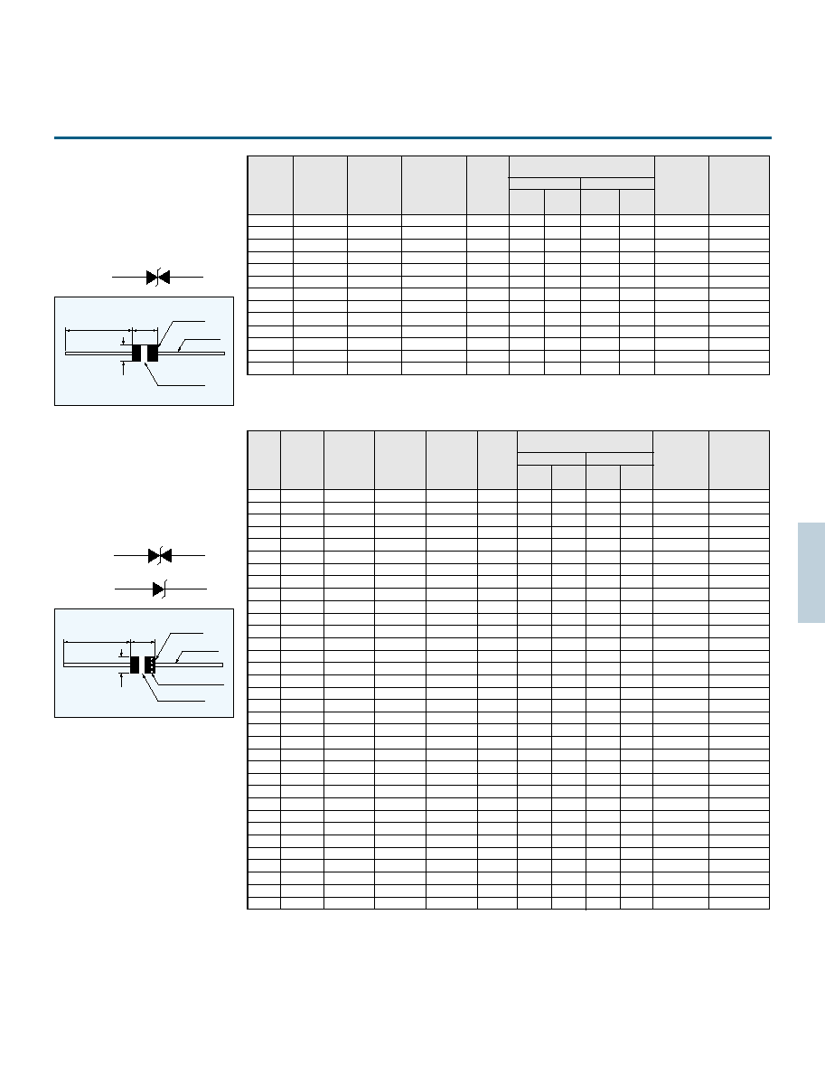
27
Z1 type VRD has bipolar electrical
characteristics.
Maximum ratings
Peak pulse power:250 W(10/1000 s)
3.00 kW(8/20 s)
Steady state power dissipation:500 mW
Operating and storage temperature
: 40 C to 125 C
Symbol mark
25 min.
6 0.3
3.6
0.3
Epoxy resin
0.8 Soldered
copper leads
Type No. Lot No.
Z2 type VRD has bipolar or unipolar
electrical characteristics.
Maximum ratings
Peak pulse power:500 W (10/1000 s)
6.00 kW (8/20 s)
Steady state power dissipation:1W
Operating and storage temperature
: 40 C to 125 C
Symbol mark
25 min.
6 0.3
3.6
0.3
Epoxy resin
0.8 Soldered
copper leads
Type No. Lot No.
Bi-polar
type
Stand-off
voltage
V
S
V
Maximum
leakage
current
I
L
A
Breakdown
voltage
V
B
V
Test
current
I
T
mA
Maximum clamping voltage &
Maximum peak pulse current
10/1000 s
8/20 s
Max. temp.
coef.
%/ C
V
C
V
V
C
V
I
p
A
I
p
A
Capacitance
(TYP)
pF
Z1015
Z1018
Z1022
Z1027
Z1033
Z1039
Z1047
Z1056
Z1068
Z1082
Z1100
Z1120
Z1150
12.1
14.5
17.8
21.8
26.8
31.6
38.1
45.4
55.1
66.4
81.0
97.0
121.0
5
5
5
5
5
5
5
5
5
5
5
5
5
13.5-16.5
16.2-19.8
19.8-24.2
24.3-29.7
29.7-36.3
35.1-42.9
42.3-51.7
50.4-61.6
61.2-74.8
73.8-90.2
90.0-110
108-132
135-165
1
1
1
1
1
1
1
1
1
1
1
1
1
22.0
26.5
31.9
39.1
47.7
56.4
67.8
80.5
98.0
118.0
144.0
173.0
215.0
11.3
9.43
7.83
6.39
5.24
4.43
3.69
3.10
2.55
2.14
1.73
1.44
1.16
28.4
34.0
41.2
50.5
61.7
73.0
88.0
105.0
127.0
153.0
187.0
222.0
277.0
106.
89.1
73.5
60.0
49.1
41.5
34.4
28.8
23.8
19.8
16.2
13.6
10.9
0.075
0.079
0.082
0.085
0.087
0.090
0.092
0.094
0.096
0.099
0.101
0.103
0.105
450
360
290
240
200
170
140
110
90
80
65
53
42
Bi-polar
type
Uni-polar
type
Stand-off
voltage
V
s
V
Maximum
leakage
current
I
L
A
Breakdown
voltage
V
B
V
Test
current
I
T
mA
Maximum clamping voltage &
Maximum peak pulse current
10/1000 s
8/20 s
V
C
V
V
C
V
I
p
A
I
p
A
Z2010
Z2012
Z2015
Z2018
Z2022
Z2027
Z2033
Z2039
Z2047
Z2056
Z2068
Z2082
Z2100
Z2120
Z2150
Z2180
Z2008U
Z2010U
Z2012U
Z2015U
Z2018U
Z2022U
Z2027U
Z2033U
Z2039U
Z2047U
Z2056U
Z2068U
Z2082U
Z2100U
Z2120U
Z2150U
Z2180U
6.63
8.10
8.10
9.72
9.72
12.1
12.1
14.5
14.5
17.8
17.8
21.8
21.8
26.8
26.8
31.6
31.6
38.1
38.1
45.4
45.4
55.1
55.1
66.4
66.4
81.0
81.0
97.2
97.2
121.0
121.0
146.0
146.0
500
100
20
5
5
5
5
5
5
5
5
5
5
5
5
5
5
5
5
5
5
5
5
5
5
5
5
5
5
5
5
5
5
7.38-9.02
9.00-11.0
9.00-11.0
10.8-13.2
10.8-13.2
13.5-16.5
13.5-16.5
16.2-19.8
16.2-19.8
19.8-24.2
19.8-24.2
24.3-29.7
24.3-29.7
29.7-36.3
29.7-36.3
35.1-42.9
35.1-42.9
42.3-51.7
42.3-51.7
50.4-61.6
50.4-61.6
61.2-74.8
61.2-74.8
73.8-90.2
73.8-90.2
90.0-110
90.0-110
108-132
108-132
135-165
135-165
162-198
162-198
10
1
1
1
1
1
1
1
1
1
1
1
1
1
1
1
1
1
1
1
1
1
1
1
1
1
1
1
1
1
1
1
1
12.5
15.0
15.0
17.3
17.3
22.0
22.0
26.5
26.5
31.9
31.9
39.1
39.1
47.7
47.7
56.4
56.4
67.8
67.8
80.5
80.5
98.0
98.0
118.0
118.0
144.0
144.0
173.0
173.0
215.0
215.0
258.0
258.0
40.0
33.4
33.4
28.9
28.9
22.7
22.7
18.8
18.8
15.7
15.7
12.8
12.8
10.5
10.5
8.86
8.86
7.37
7.37
6.21
6.21
5.10
5.10
4.24
4.24
3.47
3.47
2.89
2.89
2.32
2.32
1.94
1.94
16.3
19.5
19.5
22.7
22.7
28.4
28.4
34.0
34.0
41.2
41.2
50.5
50.5
61.7
61.7
73.0
73.0
88.0
88.0
105.0
105.0
127.0
127.0
153.0
153.0
187.0
187.0
222.0
222.0
277.0
277.0
333.0
333.0
372
311
311
267
267
213
213
178
178
147
147
120
120
98.2
98.2
83.0
83.0
68.9
68.9
57.7
57.7
47.7
47.7
39.6
39.6
32.4
32.4
27.3
27.3
21.9
21.9
18.2
18.2
NOTE: Nonsuffix:bi-polar, suffix"U" : uni-polar.
Cathode mark(Uni-polar)
Bi-polar
Uni-polar
Max. temp.
coef.
%/ C
Capacitance
(TYP)
pF
Z2008
6.63
500
7.38-9.02
10
12.5
40.0
16.3
372
0.045
0.063
0.055
0.071
0.066
0.074
0.075
0.079
0.079
0.083
0.082
0.086
0.085
0.089
0.087
0.092
0.090
0.095
0.092
0.097
0.094
0.099
0.096
0.100
0.099
0.102
0.101
0.104
0.103
0.106
0.105
0.107
0.106
0.108
1200
2400
950
1900
790
1580
640
1280
520
1040
420
840
340
680
280
560
240
480
200
400
160
320
130
260
110
220
90
180
75
150
60
120
49
98
Unit (mm)
Unit (mm)

28
Maximum ratings
Peak pulse power:1.5kW(10/1000 s)
1 8 .0kW (8/20 s)
Steady state power dissipation:2W
Operating and storage temperature
: 40 C to 125 C
Symbol mark
24 min.
9 0.5
5.3
0.5
Epoxy resin
1.0 Soldered
copper leads
Type No. Lot No.
Low capacitance type
Z6 type VRD has bipolar or unipolar
electrical characteristics.
Maximum ratings
Reverse voltage:200 VDC
Peak pulse power:250 W(10/1000 s)
3.00 kW (8/20 s)
Steady state power dissipation:500 mW
Operating and storage temperature
: 40 C to 125 C
Symbol mark
25 min.
6 0.3
3.6
0.3
Epoxy resin
0.8 Soldered
copper leads
Type No. Lot No.
Cathode mark
Cathode mark(Uni-polar)
Z6010
Z6012
Z6015
Z6018
Z6022
Z6027
Z6033
Z6039
Z6047
Z6056
Z6068
Z6082
Z6100
Z6120
Z6008U
Z6010U
Z6012U
Z6015U
Z6018U
Z6022U
Z6027U
Z6033U
Z6039U
Z6047U
Z6056U
Z6068U
Z6082U
Z6100U
Z6120U
Z6150U
16.3
19.5
19.5
22.7
22.7
28.4
28.4
34.0
34.0
41.2
41.2
50.5
50.5
61.7
61.7
73.0
73.0
88.0
88.0
105.0
105.0
127.0
127.0
153.0
153.0
187.0
187.0
222.0
222.0
277.0
1120
933
933
802
802
641
641
535
535
442
442
360
360
295
295
249
249
207
207
173
173
143
143
119
119
97.3
97.3
82.0
82.0
65.7
6.63
8.10
8.10
9.72
9.72
12.1
12.1
14.5
14.5
17.8
17.8
21.8
21.8
26.8
26.8
31.6
31.6
38.1
38.1
45.4
45.4
55.1
55.1
66.4
66.4
81.0
81.0
97.2
97.2
121.0
500
200
50
10
5
5
5
5
5
5
5
5
5
5
5
5
5
5
5
5
5
5
5
5
5
5
5
5
5
5
7.38-9.02
9.00-11.0
9.00-11.0
10.8-13.2
10.8-13.2
13.5-16.5
13.5-16.5
16.2-19.8
16.2-19.8
19.8-24.2
19.8-24.2
24.3-29.7
24.3-29.7
29.7-36.3
29.7-36.3
35.1-42.9
35.1-42.9
42.3-51.7
42.3-51.7
50.4-61.6
50.4-61.6
61.2-74.8
61.2-74.8
73.8-90.2
73.8-90.2
90.0-110
90.0-110
108-132
108-132
135-165
10
1
1
1
1
1
1
1
1
1
1
1
1
1
1
1
1
1
1
1
1
1
1
1
1
1
1
1
1
1
12.5
15.0
15.0
17.3
17.3
22.0
22.0
26.5
26.5
31.9
31.9
39.1
39.1
47.7
47.7
56.4
56.4
67.8
67.8
80.5
80.5
98.0
98.0
118.0
118.0
144.0
144.0
173.0
173.0
215.0
120
100
100
86.7
86.7
68.2
68.2
56.6
56.6
47.0
47.0
38.5
38.4
31.4
31.4
26.6
26.6
22.1
22.1
18.6
18.6
15.3
15.3
12.7
12.7
10.4
10.4
8.67
8.67
6.98
ZD015
ZD018
ZD022
ZD027
ZD033
ZD039
ZD047
ZD056
ZD068
12.8-17.2
15.3-20.7
18.7-25.3
23.0-31.0
28.1-37.9
33.2-44.8
40.0-54.0
47.6-64.4
57.8-78.2
11.4
13.7
16.8
20.6
25.2
29.8
35.9
42.8
52.0
10
10
5
5
5
5
5
5
5
1
1
1
1
1
1
1
1
1
24.0
28.0
33.2
40.0
48.6
57.4
68.5
81.0
98.0
10.4
8.93
7.53
6.25
5.14
4.35
3.65
3.08
2.55
31.0
36.0
43.0
52.0
63.0
74.0
89.0
106.0
127.0
96.7
83.3
69.7
57.7
47.6
40.5
33.7
28.6
23.8
0.075
0.079
0.082
0.085
0.087
0.090
0.092
0.094
0.096
Bi-polar
Uni-polar
Bi-polar
type
Uni-polar
type
Stand-off
voltage
V
s
V
Maximum
leakage
current
I
L
A
Breakdown
voltage
V
B
V
Test
current
I
T
mA
Maximum clamping voltage &
Maximum peak pulse current
10/1000 s
8/20 s
V
C
V
V
C
V
I
p
A
I
p
A
NOTE : Nonsuffix : Bi-polar, suffix "U" : Uni-polar.
Max. temp.
coef.
%/ C
Capacitance
(TYP)
pF
0.063
0.055
0.071
0.066
0.074
0.075
0.079
0.079
0.083
0.082
0.086
0.085
0.089
0.087
0.092
0.090
0.095
0.092
0.097
0.094
0.099
0.096
0.100
0.099
0.102
0.101
0.104
0.103
0.106
0.107
14600
5600
11200
4400
8800
3300
6600
2700
5400
2400
4400
1700
3300
1400
2800
1200
2400
1000
2000
850
1700
720
1440
610
1220
520
1040
440
880
720
Stand-off
voltage
V
S
V
Maximum
leakage
current
I
L
A
Breakdown
voltage
V
B
V
Test
current
I
T
mA
Maximum clamping voltage &
Maximum peak pulse current
10/1000 s
8/20 s
Max. temp.
coef.
%/ C
V
C
V
V
C
V
I
p
A
I
p
A
Capacitance
(TYP)
pF
VRD
type
No.
31.5
31.0
29.0
28.2
27.2
26.3
25.0
24.1
22.0
Unit (mm)
Unit (mm)

29
ZS 1 033 D- T
Taping
Nil
:
Bi-Polar
U
:
Uni-Polar
D
:
High-Reverse voltage type
Break down voltage
Steady state power
SMD type
Part number
Dimensions
Taping
Marking
4.3
0.2
4.7
0.3
1.2
0.2
1.2
0.2
0.2
2.0
0.3
0.1 max.
1.5
0.2
2.5
0.2
Symbol Mark
012
5AA
S Mark
Part No.
Lot No.
D
0
T
1
A
B
D
1
T
2
P
1
P
1
P
2
P
0
T
1
T
2
D
0
D
1
E
F
W
B
A
3.0
0.1
5.2
0.1
12.0
0.3
5.5
0.05
1.75
0.1
4.0
0.1
2.0
0.1
4.0
0.1
1.5
0.1
0
1.5
0.2
0
0.3
0.05
(2.6)
Unit (mm)
P
2
P
0
W
FE
Dimension of reel
W
1
A
178
2.0
B
80
1.0
C
13
0.5
D
21
0.8
E
2.0
0.5
W
14.0
1.5
r
(1.0)
1.5
0.5
1.0
Unit (mm)
E
C
D
r
A
W
Minimum quantity
:
1500 / reel
W
1
B
Steady state power
dissipation
Peak pulse power
Storage temp. range
Maximum Rating
1.0W
300W(10/1000 s)
1200W(1.2/50 s)
2000W(8/20 s)
40 150 C
Part No.
Breakdown
voltage
Stand-off
voltage
Temperature
coefficient
Capacitance
Maximum
leakage
current
Maximum clamping voltage &
Maximum peak pulse current
V
B
It
1mA
V
V
S
V
S
D.C.
V
I
L
max
A
10/1000 s
8/20 s
V
C
max/I
pp
V
V
A
A
pF
C
25 C
50 C
%/ C
Specifications
ZS type
ZS1012
ZS1015
ZS1018
ZS1022
ZS1027
ZS1033
ZS1039
ZS1047
12(10.8
13.2)
15(13.5
16.5)
18(16.2
19.8)
22(19.8
24.2)
27(24.3
29.7)
33(29.7
36.3)
39(35.1
42.9)
47(42.3
51.7)
9.72
12.1
14.5
17.8
21.8
26.8
31.6
38.1
10
5
5
5
5
5
5
5
17.3
22.0
26.5
31.9
39.1
47.7
56.4
67.8
17.3
13.6
11.3
9.40
7.67
6.29
5.32
4.42
22.4
28.5
34.4
41.4
50.7
61.8
73.1
88.0
89.3
70.2
58.1
48.3
39.4
32.4
27.4
22.7
0.066
0.075
0.079
0.082
0.085
0.087
0.090
0.092
551
465
376
299
248
198
164
137
Part No.
Breakdown
voltage
Stand-off
voltage
Temperature
coefficient
Capacitance
(TYP)
Maximum
leakage
current
Maximum clamping voltage &
Maximum peak pulse current
V
B
It
1mA
V
V
S
V
S
D.C.
V
I
L
max
A
10/1000 s
8/20 s
V
C
max/I
pp
V
V
A
A
pF
C
25 C
50 C
%/ C
ZS1012D
ZS1015D
ZS1018D
ZS1022D
ZS1027D
ZS1033D
ZS1039D
ZS1047D
12(10.8
13.2)
15(13.5
16.5)
18(16.2
19.8)
22(19.8
24.2)
27(24.3
29.7)
33(29.7
36.3)
39(35.1
42.9)
47(42.3
51.7)
9.72
12.1
14.5
17.8
21.8
26.8
31.6
38.1
10
5
5
5
5
5
5
5
17.3
22.0
26.5
31.9
39.1
47.7
56.4
67.8
17.3
13.6
11.3
9.40
7.67
6.29
5.32
4.42
22.4
28.5
34.4
41.4
50.7
61.8
73.1
88.0
89.3
70.2
58.1
48.3
39.4
32.4
27.4
22.7
0.066
0.075
0.079
0.082
0.085
0.087
0.090
0.092
30.2
29.1
28.2
27.3
26.4
25.5
24.8
24.0
ZS-D type
ZS-U type
Part No.
Breakdown
voltage
Stand-off
voltage
Temperature
coefficient
Capacitance
Maximum
leakage
current
Maximum clamping voltage &
Maximum peak pulse current
V
B
It
1mA
V
V
S
V
S
D.C.
V
I
L
max
A
10/1000 s
8/20 s
V
C
max/I
pp
V
V
A
A
pF
C
25 C
50 C
%/ C
ZS1012U
ZS1015U
ZS1018U
ZS1022U
ZS1027U
ZS1033U
ZS1039U
ZS1047U
12(10.8
13.2)
15(13.5
16.5)
18(16.2
19.8)
22(19.8
24.2)
27(24.3
29.7)
33(29.7
36.3)
39(35.1
42.9)
47(42.3
51.7)
9.72
12.1
14.5
17.8
21.8
26.8
31.6
38.1
10
5
5
5
5
5
5
5
17.3
22.0
26.5
31.9
39.1
47.7
56.4
67.8
17.3
13.6
11.3
9.40
7.67
6.29
5.32
4.42
22.4
28.5
34.4
41.4
50.7
61.8
73.1
88.0
89.3
70.2
58.1
48.3
39.4
32.4
27.4
22.7
0.066
0.075
0.079
0.082
0.085
0.087
0.090
0.092
1,102
929
751
598
497
395
328
274
SMD VRD
Unit(mm)
012
5AA
S Mark
Cathode
Mark
S Mark
Cathode
Mark
Part No.
Lot No.
Symbol Mark
012
5AA
Part No.
Lot No.
Symbol Mark
ZS type
ZS-U type
ZS-D type
career tape
cover tape
(TYP)
(TYP)

30
CURRENT REGULATIVE DIODE
CRD
CRD is a diode which supplies constant
current to an electric circuit, even when
power supply voltage fluctuations or load
impedance fluctuations occur.
CRD is used for current stabilization and
current limiting.
1.8 0.2
0.5 0.1
1.35 0.1
0.3
0.3
Solder-plated
electrode
Solder-plated
electrode
(Cathode mark)
Band 1 Black
Band 3
Band 2
Glass sleeve
3.5
0.2
3.9
0.3
26 min.
Cathode
band
Anode
Cathode
Mark
Unit(mm)
F type
E type
100V
Voltage (V)
V
B
10V
V
K
V
R
I
R
I
P
0.8 I
P
Current (mA)
Explanation of terms
I
P :
Pinch-off current at 10V
V
K:
Voltage which produces
0.8Ip or greater current
V
B:
Breakdown voltage
I
R :
Permitted reverse current
Basic characteristics
Taping
Specifications
There are three Types for taping.
Minimum taping quantity for
Type 1 Roll..........5000pcs
Box..........2500pcs
Type 2 4000pcs
Type 3 2500pcs
Maximum ratings
Maximum rating voltage
Rating power
Thermal resistance
Reverse current
Operating temp
E101L E-562
E-822
E-103
E-123
E-153
Voltage
100V
30
30
30
25
E type
300mW
300 C/ W
F type
400mW
150 C/ W
30 C 150 C
50mA
F101L F-562
F-822
F-103
F-123
F-153
Voltage
100V
50
42
34
28
Type 1
Type 3
20 0.5
0 2
3 0.5
6.35 0.5
26.3 0.5
13 2
5 0.8
12.7 0.3
4.0 0.3
0.2 0.05
1.7 0.1
1.7 0.1
4.0 0.1
4.0 0.1
2.0 0.05
18
Insulation
2.75 max.
1.0
0.5
1.5
0.1
0
Type 2
3
3
Pulling
direction
Part retaining
square hole
Feeding
round hole
8.0 0.3
1.75 0.1
3.5
0.05
3.7
0.1
Unit(mm)
Unit(mm)
Unit(mm)
*In principal elements are set with cathode side on the round
hole side.
5 0.5
6 0.1
1.2 max.
1 max.
L
1
L
1
L
2
1.5
L
2
26 or 52
*1,*2 Pinch-off current limiting current are measured by impulse wave at 25 C
*3 Z
T
is minimum AC impedance when small AC signal voltage of 10KHz is added tc 25 V
DC
bias. Z
T
is used as the reference value.
*4 Temperature coefficient is measured between 25 C and 50 C.
F-101L
F-101
F-301
F-501
F-701
F-102
F-152
F-202
F-272
F-352
F-452
F-562
F-822
F-103
F-123
F-153
E-101L
E-101
E-301
E-501
E-701
E-102
E-152
E-202
E-272
E-352
E-452
E-562
E-822
E-103
E-123
E-153
Light blue
Light blue
Light blue
Light blue
Light blue
Yellow green
Yellow green
Yellow green
Yellow green
Yellow green
Yellow green
Yellow green
Yellow green
Orange
Orange
Orange
White
Pink
Orange
Yellow green
Blue
Pink
Orange
Yellow green
Light blue
Blue
Purple
White
Yellow
Pink
White
Light blue
10V
10V
10V
10V
10V
10V
10V
10V
10V
10V
10V
10V
10V
10V
10V
10V
1L
01
03
05
07
10
15
20
27
35
45
56
82
10
12
15
0.01 0.06
0.05 0.21
0.20 0.42
0.40 0.63
0.60 0.92
0.88 1.32
1.28 1.72
1.68 2.32
2.28 3.10
3.00 4.10
3.90 5.10
5.00 6.50
6.56 9.84
8.00 12.0
9.60 14.4
12.0 18.0
0.4
0.5
0.8
1.1
1.4
1.7
2.0
2.3
2.7
3.2
3.7
4.5
3.1
3.5
3.8
4.3
0.8lpmin.
0.8lpmin.
0.8lpmin.
0.8lpmin.
0.8lpmin.
0.8lpmin.
0.8lpmin.
0.8lpmin.
0.8lpmin.
0.8lpmin.
0.8lpmin.
0.8lpmin.
0.8lpmin.
0.8lpmin.
0.8lpmin.
0.8lpmin.
8.00
6.00
4.00
2.00
1.00
0.65
0.40
0.25
0.15
0.10
0.07
0.04
0.32
0.17
0.08
0.03
1.1 max.
1.1max.
1.1max.
1.1max.
1.1max.
1.1max.
1.1max.
1.1max.
1.1max.
1.1max.
1.1max.
1.1max.
*1.0max.
*1.0max.
*1.0max.
*1.0max.
2.10
0.10
2.10
0.10
0.40
0.20
0.15
0.25
0.00
0.32
0.10
0.37
0.13
0.40
0.15
0.42
0.18
0.45
0.20
0.47
0.22
0.50
0.25
0.53
0.25
0.45
0.25
0.45
0.25
0.45
0.25
0.45
Part No.
Part No.
Part No.
Indication
F type
Band 2
Band 3
E
Type
Pinch-off current*
1
Limiting current*
2
Dynamic*
3
impedance
Z
T
(M )
Temperature*
4
coefficient
(%/ C)
Limiting
current ratio
I
100V
/Ip*I
30V
/Ip
Test
Voltage
with
lead
lead
less
Ip(mA)
V
K
(V)
I
K
(mA)

31
Power derating
Pinch-off current Temperature
0.05
0.5
1
2
5
10
20
50
100
200
0.1
0.2
0.5
1.0
2.0
5.0
10
20
0.05
0.5
1
2
5
10
20
50
100
200
0.1
0.2
0.5
1.0
2.0
5.0
10
20
E-562
E-452
E-352
E-272
E-202
E-152
E-102
E-701
E-501
E-301
E-101
E-101L
E-153
E-123
E-103
E-822
F-562
F-452
F-352
F-272
F-202
F-152
F-102
F-701
F-501
F-301
F-101
F-101L
F-153
F-123
F-103
F-822
400
350
300
250
200
150
100
50
0
20
40
60
80
100
120
140
160
180
Ambient temperature
Power (mW)
E type
400
350
300
250
200
150
100
50
0
20
40
60
80
100
120
140
160
180
Ambient temperature
temperature
Pinch-off current (mA)
Power (mW)
F type
CRD in parallel
The use of CRD in parallel increases their current
handling capabilities.
The compensation of current reduction due to self
heating
Placing resistors in parallel with CRD can correct
any current decrease when the applied voltage
increases. The following values are typical for
correction resistors.
Compensative resistor is not necessary if the
current value is less than 1 mA.
E-102
1M
E-152
390k
E-202
240k
E-272
120k
E-352
82k
E-452
56k
E-562
39k
Increasing the voltage range using a zener diode
Connecting zener diodes in series with the line ensures
that the current is constant in high-voltage area.
Dynamic characteristics (saturation characteristics)
0
Voltage (V)
V
2
Z
D
Current (mA)
5
1
2
3
5
7
10
20
50
100
Voltage (V)
Current (mA)
CRD
10
5
1.0
0.1
0.01
30
0
30
60
90
120
150
E-153
E-272
E-202
E-152
E-102
E-701
E-501
E-301
E-101
E-123
E-103
E-822
E-562
E-452
E-352
E-452
Current (mA)
Current (mA)
Voltage (V)
Voltage (V)
( C)
( C)
( C)

32
Features
METAL OXIDE VARISTOR
ZENAMIC
ZENAMIC is the product name of a metal
oxide varistor.
ZENAMIC Transient / Surge Absorber, Series
D is newly released through our continued
research in ceramic material composition of
ZnO varistor and manufacturing process,
featuring large surge current handling
capability and energy handling capability
for absorbing transient overvoltage in
compact size.
Improved in "Surge Current Handling
Capability (@8 / 20 s, 2 times)" by about 2
times over the current.
Very large "Energy Handling Capability"
absorbing transient overvoltages in
compact sizes.
Lower Clamping Voltage for better surge
protection.
Fast response to high speed transient /
surge voltage.
Wide products range for transient / surge
protection on AC 100V to AC 480V
nominal system with the maximum peak
current ratings of 600A to 7000A (@8 / 20
s, 2 times).
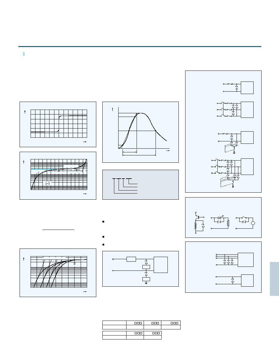
33
ZENAMIC has the forward-reverse symmetrical
electrical characteristics as shown in the figure 1.
The voltage-current curves show the varistor
characteristics in the range 1 A to 10
4
A, and show
the resistance characteristics for the range under
1 A and over 10
4
A in the figure 2.
The voltage across terminals when test current(It:
1 mA)is applied to ZENAMIC is the standard varistor
voltage(Vz), and the voltage across terminals when
a standard surge(Ip) is applied represents the
maximum suppression voltage(Vc).
Z 10 D 221
Varistor voltage
D series
Element diameter
ZENAMIC symbol
V- characteristics
A surge waveform varies according to the sources.
An EXP waveform is used for surge testing of
ZENAMIC, while a AC half-wave is used for the
energy absorption test. The EXP waveform reaches
its peak voltage (current) at [ta] as shown in the
figure 5, and then decreases as time passes and
reaches half of the peak voltage (current) at [tb].
This type of the EXP waveform is shown as a [ta / tb]
voltage (current) waveform. For surge testing
of ZENAMIC, the 8 / 20
sec current waveform is
used.
Surge waveform
Power lines and surge absorption units with error
display (SA series).
Applications
In the small current range, ZENAMIC features
outstanding temperature characteristics. A shunt
resistance Rp of metal oxide varistor has the
temperature characteristics which is determined by
the following equation.
Temperature characteristics
1.A surge excess of the specified Maximum Peak
Current may cause short circuit or mechanical
damage. The following measures are recommended.
In case that ZENAMIC is used in line to ground, the
ground fault circuit interrupter shall be applied in
location A or thermally coupled fuse shall be
applied in location C.
ZENAMIC shall not be used near heat generating
device and free from direct sunlight.
ZENAMIC shall not be used near the flammable
materials.
1) Location of the over current protector(circuit breaker
or current fuse)shall be in the power line to the
circuit(Location A)or in series with ZENAMIC
(Location B).
2) It recommended that a fuse listed in the table be put
in location A or B.
3) In case that ZENAMIC is used in line to ground, the
ground fault circuit interrupter should be applied in
location A or thermally coupled fuse should be applied
in location C.
Application notes(General)
Part No.
0
200
200
400
400
0
1
2
3
4
5
1
2
3
4
5
Current (A)
Time( s)
Current (%)
Voltage(V)
Fig 1
Fig 5
5
10
20
50
200
500
100
2,000
1,000
10
10
9
10
8
10
7
10
6
10
5
10
4
10
3
10
2
10
1
10
0
10
1
10
2
10
3
10
4
10
Current (A)
Voltage(V)
Fig 2
Clamping voltage
Varistor voltage
R
p
R
s
Test current
Surge current
I
C
E
10
20
50
40
30
200
500
400
300
100
10
10
9
10
8
10
7
10
6
10
5
10
4
10
3
10
2
10
1
10
Current (A)
Voltage(V)
Fig 3
100
90
50
10
0
ta
tb
Rp AeEg / 2kT
T:Absolute temperature
k : Boltzmann constant
A, Eg:constants
As shown in the figure 3, the temperature dependence
characteristics are shown clearly in the low current area.
(2)
Test current
25 C
60 C 90 C 120 C
Protected
Equipment
COM
.
Surge protection of
signal Line
Surge protection of
telephone Line
Telephone
Protected
circuit
Power line
A
B
C
Protected
circuit
Part Number
Rating of fuse
3A max.
5A max.
7A max.
Part Number
Rating of fuse
Refer to the related Safety Standards.
10A max.
15A max.
Line to line protection
Line to line and line to ground protection
Single line and telephone line surge protection
DC
AC single phase
AC three phase
Protected
circuit
f
Protected
circuit
DC
AC single phase
Switching surge
protection
Semiconductor
protection
Contact spark
suppression
f
f
f
f
f
AC three phase
Protected
circuit
f
f
f
f
Thermal
coupling
Thermal
coupling
M
Motor
Z5D
Z7D
Z10D
Z15D
Z21D

34
Z5D Series
Specifications
Part No.
Varistor
Voltage
V
0.1mA
(V)
Maximum
Allowable
Voltage
AC
rms
(V)
DC(V)
Clamping
Voltage
(max.)
Rated
Power
Maximum
Energy
Maximum
Peak Current
(8/20 s)
Capacitance
(max.)
1kHz
V(V)
(W)
(J)
(J)
(A)
(A)
(pF)
(10/1000 s)
(2ms)
1 time
2 times
Z5D180
Z5D220
Z5D270
Z5D330
Z5D390
Z5D470
Z5D560
Z5D680
*1
Z5D820
*1
Z5D101
*1
Z5D121
*1
Z5D151
*1
Z5D201
*1
Z5D221
*1
Z5D241
*1
Z5D271
*1
Z5D331
*1
Z5D361
*1
Z5D391
*1
Z5D431
*1
Z5D471
18(16-20)
22(20-24)
27(24-30)
33(30-36)
39(35-43)
47(42-52)
56(50-62)
68(61-75)
82(74-90)
100(90-110)
120(108-132)
150(135-165)
200(185-225)
220(198-242)
240(216-264)
270(247-303)
330(297-363)
360(324-396)
390(351-429)
430(387-473)
470(423-517)
11
14
17
20
25
30
35
40
50
60
75
95
130
140
150
175
210
230
250
275
300
14
18
22
26
31
38
45
56
65
85
100
125
170
180
200
225
270
300
320
350
385
40 at 1A
48
60
73
86
104
123
150
145 at 5A
175
210
260
355
380
415
475
570
620
675
754
810
0.01
0.01
0.01
0.01
0.01
0.01
0.01
0.01
0.1
0.1
0.1
0.1
0.1
0.1
0.1
0.1
0.1
0.1
0.1
0.1
0.1
0.6
0.7
0.9
1.1
1.2
1.5
1.8
2.2
3.5
4.0
5.0
6.5
8.5
9.0
10.5
11.0
13.0
16.0
17.0
20.0
21.0
0.4
0.5
0.7
0.8
0.9
1.1
1.3
1.6
2.5
3.0
3.5
4.5
6.0
6.5
7.5
8.0
9.5
11.0
12.0
13.0
15.0
250
250
250
250
250
250
250
250
800
800
800
800
800
800
800
800
800
800
800
800
800
125
125
125
125
125
125
125
125
600
600
600
600
600
600
600
600
600
600
600
600
600
1600
1500
1450
1400
700
650
600
580
460
400
350
300
120
110
100 *
2
90 *
2
80 *
2
80 *
2
80 *
2
70 *
2
60 *
2
Z7D Series
Specifications
Part No.
Varistor
Voltage
V
1mA
(V)
Maximum
Allowable
Voltage
AC
rms
(V)
DC(V)
Clamping
Voltage
(max.)
Rated
Power
Maximum
Energy
Maximum
Peak Current
(8/20 s)
Capacitance
(max.)
1kHz
V(V)
(W)
(J)
(J)
(A)
(A)
(pF)
(10/1000 s)
(2ms)
1 time
2 times
Z7D180
Z7D220
Z7D270
Z7D330
Z7D390
Z7D470
Z7D560
Z7D680
18(16-20)
22(20-24)
27(24-30)
33(30-36)
39(35-43)
47(42-52)
56(50-62)
68(61-75)
11
14
17
20
25
30
35
40
14
18
22
26
31
38
45
56
36 at 2.5A
43
53
65
77
93
110
135
0.02
0.02
0.02
0.02
0.02
0.02
0.02
0.02
1.1
1.3
1.6
2.0
2.4
2.8
3.4
4.1
0.9
1.1
1.3
1.6
1.9
2.3
2.7
3.3
500
500
500
500
500
500
500
500
250
250
250
250
250
250
250
250
3800
3600
3400
2900
1600
1550
1500
1200
*1
Z7D820
*1
Z7D101
*1
Z7D121
*1
Z7D151
*1
Z7D201
*1
Z7D221
*1
Z7D241
*1
Z7D271
*1
Z7D331
*1
Z7D361
*1
Z7D391
*1
Z7D431
*1
Z7D471
*1
Z7D511
82(74-90)
100(90-110)
120(108-132)
150(135-165)
200(185-225)
220(198-242)
240(216-264)
270(247-303)
330(297-363)
360(324-396)
390(351-429)
430(387-473)
470(423-517)
510(459-561)
50
60
75
95
130
140
150
175
210
230
250
275
300
320
65
85
100
125
170
180
200
225
270
300
320
350
385
410
135 at 10A
165
200
250
340
360
395
455
545
595
650
710
775
845
0.25
0.25
0.25
0.25
0.25
0.25
0.25
0.25
0.25
0.25
0.25
0.25
0.25
0.25
7
8.5
10
13
17.5
19
21
24
28
32
35
40
42
45
5
6
7
9
12.5
13.5
15
17
20
23
25
27.5
30
32
810
700
590
500
200
190
170
150
130
130
130
120
100 *
2
90 *
2
1750
1750
1750
1750
1750
1750
1750
1750
1750
1750
1750
1750
1750
1750
1250
1250
1250
1250
1250
1250
1250
1250
1250
1250
1250
1250
1250
1250
1. Operating temperature range: 40 to 85 C
2. Storage temperature range: 40 to 125 C
*1 UL 1449 approved model
*2 Measured at 1MHz

35
Z10D Series
Specifications
Part No.
Varistor
Voltage
V
1mA
(V)
Maximum
Allowable
Voltage
AC
rms
(V)
DC(V)
Clamping
Voltage
(max.)
Rated
Power
Maximum
Energy
Maximum
Peak Current
(8/20 s)
Capacitance
(max.)
1kHz
V(V)
(W)
(J)
(J)
(A)
(A)
(pF)
(10/1000 s)
(2ms)
1 time
2 times
1. Operating temperature range: 40 to 85 C
2. Storage temperature range: 40 to 125 C
* UL 1449 approved model
Z10D180
Z10D220
Z10D270
Z10D330
Z10D390
Z10D470
Z10D560
Z10D680
18(16-20)
22(20-24)
27(24-30)
33(30-36)
39(35-43)
47(42-52)
56(50-62)
68(61-75)
11
14
17
20
25
30
35
40
14
18
22
26
31
38
45
56
36 at 5A
43
53
65
77
93
110
135
0.05
0.05
0.05
0.05
0.05
0.05
0.05
0.05
2.6
3.2
3.9
4.8
5.6
6.8
8.1
9.8
2.2
2.6
3.2
4.0
4.7
5.6
6.7
8.2
1000
1000
1000
1000
1000
1000
1000
1000
500
500
500
500
500
500
500
500
16000
11000
8000
6300
5200
4600
3750
2800
* Z10D820
* Z10D101
* Z10D121
* Z10D151
* Z10D201
* Z10D221
* Z10D241
* Z10D271
* Z10D331
* Z10D361
* Z10D391
* Z10D431
* Z10D471
* Z10D511
* Z10D561
* Z10D681
* Z10D751
* Z10D821
* Z10D911
* Z10D102
82(74-90)
100(90-110)
120(108-132)
150(135-165)
200(185-225)
220(198-242)
240(216-264)
270(247-303)
330(297-363)
360(324-396)
390(351-429)
430(387-473)
470(423-517)
510(459-561)
560(504-616)
680(612-748)
750(675-825)
820(738-902)
910(819-1001)
1000(900-1100)
50
60
75
95
130
140
150
175
210
230
250
275
300
320
350
420
460
510
550
625
65
85
100
125
170
180
200
225
270
300
320
350
385
410
450
560
615
670
745
825
0.4
0.4
0.4
0.4
0.4
0.4
0.4
0.4
0.4
0.4
0.4
0.4
0.4
0.4
0.4
0.4
0.4
0.4
0.4
0.4
14
17
20
25
35
39
42
49
58
65
70
80
85
92
92
92
100
110
130
140
10
12
14.5
18
25
27.5
30
35
42
45
50
55
60
67
67
67
70
80
90
100
3500
3500
3500
3500
3500
3500
3500
3500
3500
3500
3500
3500
3500
3500
3500
3500
3500
3500
3500
3500
2500
2500
2500
2500
2500
2500
2500
2500
2500
2500
2500
2500
2500
2500
2500
2500
2500
2500
2500
2500
2000
1700
1400
1100
430
410
380
350
300
300
300
270
230
210
200
170
160
140
120
110
Z15D Series
Specifications
Part No.
Varistor
Voltage
V
1mA
(V)
Maximum
Allowable
Voltage
AC
rms
(V)
DC(V)
Clamping
Voltage
(max.)
Rated
Power
Maximum
Energy
Maximum
Peak Current
(8/20 s)
Capacitance
(max.)
1kHz
V(V)
(W)
(J)
(J)
(A)
(A)
(pF)
(10/1000 s)
(2ms)
1 time
2 times
Z15D180
Z15D220
Z15D270
Z15D330
Z15D390
Z15D470
Z15D560
Z15D680
18(16-20)
22(20-24)
27(24-30)
33(30-36)
39(35-43)
47(42-52)
56(50-62)
68(61-75)
11
14
17
20
25
30
35
40
14
18
22
26
31
38
45
56
36 at 10A
43
53
65
77
93
110
135
0.1
0.1
0.1
0.1
0.1
0.1
0.1
0.1
5.2
6.3
7.8
9.5
11
14
16
20
4.3
5.3
6.5
7.9
9.4
11
13
16
2000
2000
2000
2000
2000
2000
2000
2000
1000
1000
1000
1000
1000
1000
1000
1000
25000
20000
16000
12200
7000
6750
6500
5500
* Z15D820
* Z15D101
* Z15D121
* Z15D151
* Z15D201
* Z15D221
* Z15D241
* Z15D271
* Z15D331
* Z15D361
* Z15D391
* Z15D431
* Z15D471
* Z15D511
* Z15D561
* Z15D681
* Z15D751
* Z15D821
* Z15D911
* Z15D102
82(74-90)
100(90-110)
120(108-132)
150(135-165)
200(185-225)
220(198-242)
240(216-264)
270(247-303)
330(297-363)
360(324-396)
390(351-429)
430(387-473)
470(423-517)
510(459-561)
560(504-616)
680(612-748)
750(675-825)
820(738-902)
910(819-1001)
1000(900-1100)
50
60
75
95
130
140
150
175
210
230
250
275
300
320
350
420
460
510
550
625
65
85
100
125
170
180
200
225
270
300
320
350
385
410
450
560
615
670
745
825
135 at 50A
165
200
250
340
360
395
455
545
595
650
710
775
845
930
1120
1240
1355
1500
1650
0.6
0.6
0.6
0.6
0.6
0.6
0.6
0.6
0.6
0.6
0.6
0.6
0.6
0.6
0.6
0.6
0.6
0.6
0.6
0.6
28
35
42
53
70
78
84
99
115
130
140
155
175
190
190
210
235
255
280
20
25
30
37.5
50
55
60
70
80
90
100
110
125
136
136
136
150
165
180
200
6000
6000
6000
6000
6000
6000
6000
6000
6000
6000
6000
6000
6000
6000
6000
5000
5000
5000
5000
5000
4500
4500
4500
4500
4500
4500
4500
4500
4500
4500
4500
4500
4500
4500
4500
4500
4500
4500
4500
3700
3200
2700
2200
770
740
700
640
580
540
500
450
400
350
340
320
310
280
250
230
135
165
200
250
340
360
395
455
545
595
650
710
775
845
930
1120
1240
1355
1500
1650
at 25A
190
4500

36
Dimensions
12.5 max.
16.0 max.
9.1 max.
9.1 max.
5.8 max.
6.0 max.
7 max.
8.5 max.
22.5 max.
9.5 max.
15.5 max.
19.0 max.
10.0 max.
11.5max.
25.5 max.
20.0 min.
20.0min.
20.0 min.
20.0 min.
20.0 min.
7.5 1
7.5 1
5 1
5 1
10 1.0
10 1.0
7.5 1
7.5 1
5 1
5 1
0.8
0.8
0.6
0.6
1.0
7.2 max.
7.2 max.
4.1 max.
4.3 max.
7.4 max.
7.2 max.
7.2 max.
4.1 max.
4.3 max.
7.4 max.
P
2
P
D
A
P
1
L
F
P
O
D
0
d
W
0
W
1
W
2
H
0
H
W
t
h
T
P
2
P
D
A
P
1
L
F
P
O
D
0
d
W
0
W
1
W
2
H
0
H
W
t
h
T
Z5D
Z21D
Crimped Leads and Taped
Z7D
Z10D
Z15D
Z5D T4C
Z7D T4C
Straight Leads and Taped
Z5D T4D
Z7D T4D
*Dimension''T'':Conforms to each individual specification
*Packing quantily:1000pcs/BOX
Symbol
P
F
W
h
d
D
Z5D:7max,
Z7D:8.5max
D
Z5D:7max,
Z7D:8.5max
P
0
P
1
P
2
Type
12.7 1.0
5.0 0.5
18.0
0 2
0.60
12.7 0.3
3.85 0.70
6.35 1.30
0.06
0.05
1.0
0.5
Symbol
t
L
W
1
W
0
W
2
H
0
H
Type
5.0min
4.0 0.2
17.0 0.5
0.6 0.3
9.0 0.5
3max
11max
Approx. 22
5.0min
4.0 0.2
17.0 0.5
0.6 0.3
9.0 0.5
3max
11max
Approx. 20
*Dimension"T":Conforms to each individual specification
*Packing quantily:1000pcs/BOX
P
F
W
h
d
P
0
P
1
P
2
12.7 1.0
5.0 0.5
18.0
0 2
0.60
12.7 0.3
3.85 0.70
6.35 1.30
0.06
0.05
1.0
0.5
t
L
D
0
D
0
W
1
W
0
W
2
H
0
H
Unit(mm)
Z21D Series
Specifications
Part No.
Varistor
Voltage
V
1mA
(V)
Maximum
Allowable
Voltage
AC
rms
(V)
DC(V)
Clamping
Voltage
(max.)
Rated
Power
Maximum
Energy
Maximum
Peak Current
(8/20 s)
Capacitance
(max.)
1kHz
V(V)
(W)
(J)
(J)
(A)
(A)
(pF)
(10/1000 s)
(2ms)
1 time
2 times
1. Operating temperature range: 40 to 85 C
2. Storage temperature range: 40 to 125 C
Z21D180
Z21D220
Z21D270
Z21D330
Z21D390
Z21D470
Z21D560
Z21D680
18(16-20)
22(20-24)
27(24-30)
33(30-36)
39(35-43)
47(42-52)
56(50-62)
68(61-75)
11
14
17
20
25
30
35
40
14
18
22
26
31
38
45
56
36 at 20A
43
53
65
77
93
110
135
0.2
0.2
0.2
0.2
0.2
0.2
0.2
0.2
13
16
19
24
28
34
41
49
12
14
17
21
25
30
36
44
3000
3000
3000
3000
3000
3000
3000
3000
2000
2000
2000
2000
2000
2000
2000
2000
40000
30000
24500
20000
13800
13500
12200
11500
*
Z21D820
*
Z21D101
*
Z21D121
*
Z21D151
*
Z21D201
*
Z21D221
*
Z21D241
*
Z21D271
*
Z21D331
*
Z21D361
*
Z21D391
*
Z21D431
*
Z21D471
*
Z21D511
*
Z21D561
*
Z21D681
*
Z21D751
*
Z21D821
*
Z21D911
*
Z21D102
82(74-90)
100(90-110)
120(108-132)
150(135-165)
200(185-225)
220(198-242)
240(216-264)
270(247-303)
330(297-363)
360(324-396)
390(351-429)
430(387-473)
470(423-517)
510(459-561)
560(504-616)
680(612-748)
750(675-825)
820(738-902)
910(819-1001)
1000(900-1100)
50
60
75
95
130
140
150
175
210
230
250
275
300
320
350
420
460
510
550
625
65
85
100
125
170
180
200
225
270
300
320
350
385
410
450
560
615
670
745
825
135 at 100A
165
200
250
340
360
395
455
545
595
650
710
775
845
930
1120
1240
1355
1500
1650
1.0
1.0
1.0
1.0
1.0
1.0
1.0
1.0
1.0
1.0
1.0
1.0
1.0
1.0
1.0
1.0
1.0
1.0
1.0
1.0
56
70
85
106
140
155
168
190
228
255
275
303
350
382
382
420
460
510
565
40
50
60
75
100
110
120
135
160
180
195
215
250
273
273
273
300
325
360
400
10000
10000
10000
10000
10000
10000
10000
10000
10000
10000
10000
10000
10000
10000
7500
7500
7500
7500
7500
6500
6500
6500
6500
6500
6500
6500
6500
6500
6500
6500
6500
6500
6500
6500
6500
6500
6500
6500
6500
7500
6500
5500
4500
1700
1600
1500
1300
1100
1100
1100
1000
900
800
750
650
600
530
500
450
*
UL 1449 approved model
382
7500
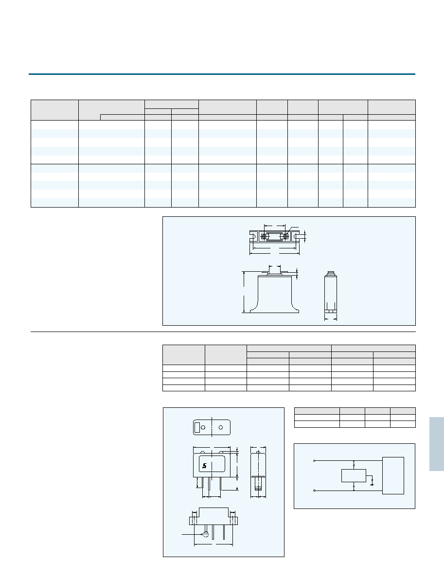
37
Dimensions
Dimensions
Application
Z25M, Z33M type
The said unit is connected to line and ground, and
protects an electric appliance from the surge
influence. When the unit was broken by the surge of
over rated current, it shows trouble in lighting
LED. The socket of exclusive use for the unit, shown
in right side figure, is also suppliable.
Power supply line
Unit
Z25M, Z33M Series
SURGE ABSORBER UNIT
4.3
5
24
12
14
51 1
60 1
55
1
ISO
M4
Zenamic
Z33M441
JAPAN
17
SA
100V
SA-100V
1E
W
D
38
9
3
3
12.5
H
12.5
9.5
0
1.5
use as
short
circuit
(7.5) (7.5)
Unit(mm)
Unit(mm)
Absorption
unit
C
A
B
Part No.
Min
Max
Varistor voltage V
1mA
(V)
Maximum allowable
voltage
AC
DC
Maximum clamping
voltage
Rated
wattage
Energy
(2ms)
Withstanding
Surge current
(8/20 s)
Typical
capacitance
(@1kHz)
V
W
J
pF
1 Time
2 Times
Z25M221S
Z25M271S
Z25M331S
Z25M391S
Z25M441S
Z25M471S
Z25M561S
Z25M681S
Z25M821S
Z25M102S
Z33M221S
Z33M271S
Z33M331S
Z33M391S
Z33M441S
Z33M471S
Z33M561S
Z33M681S
Z33M821S
Z33M102S
220(187
253 )
270(229.5
310.5)
330(280.5
379.5)
390(331.5
448.5)
440(374
506 )
470(399.5
540.5)
560(476
644 )
680(578
782 )
820(697
943 )
1000(850
1,150)
220(187
253 )
270(229.5
310.5)
330(280.5
379.5)
390(331.5
448.5)
440(374
506 )
470(399.5
540.5)
560(476
644 )
680(578
782 )
820(697
943 )
1000(850
1150)
120
150
175
210
240
250
300
365
440
520
125
155
185
215
225
235
260
280
330
375
200
255
310
360
370
385
425
460
580
620
3300
2200
1900
1700
1500
1500
1400
1250
800
500
5500
4200
3700
3200
2800
2600
2200
1800
1500
1000
165
210
245
295
335
350
420
510
615
730
120
150
175
210
240
250
300
365
440
520
165
210
245
295
335
350
420
510
615
730
380 at 150A
465
570
675
760
810
970
1175
1415
1725
380 at 200A
465
570
675
760
810
970
1175
1415
1725
V
V
rms
1.0
1.2
15000A
25000A
10000A
20000A
Specifications
48V DC
100V AC
200V AC
240V AC
SA- 50V
SA-100V
SA-200V
SA-240V
65V
DC
140V
AC
250V
AC
300V
AC
180V
DC
or 140V
DC
240V
AC
510V
AC
510V
AC
1250
1250
1250
1250
SA-50V, 100V
SA-200V, 240V
40 1
40 1
15
18 1
30 1
35 1
1500
1250
1500
1500
Line
voltage
Part No.
Part No.
W
D
H
Rating voltage
line-line
V
V
ground-line
Rating current
line-line
A
A
ground-line
Clamping voltage is measured by( )V peak voltage wave with line impedance of 50
Specifications table SA series
2
1
(mm)
1. Operating temperature range: 40 to 85 C
2. Storage temperature range: 40 to 125 C

38
ZENAMIC
Reliability
Characteristics
Criterion
Test Methods/Descriptions
Standard Test Condition
Varistor Voltage
Maximum Allowable Voltage
Maximum Energy
Clamping Voltage
Rated Power
Maximum
Peak Current
(Withstanding
Surge Current)
Temperature Coefficient of
Varistor Voltage
Capacitance
Withstanding Voltage
(Body lnsulation)
lmpulse Life
Electrical
2 times
1 times
Unless other wise specified, electrical measurements (initial/aftertests) shall
be conducted at temperature of 5 to 35 C,relative humidity of 45 to 85%
and atmospheric pressure of 860 to 1060 hPa.
The voltage between two terminals with the specified measuring current C
mA
DC applied is called Vc or Vc
mA
. The measurement shall be made as fast as
possible to avoid heat affection.
The maximum sinusoidal RMS voltage or maximum DC voltage that can be
applied continuously in the specified operating temperature range.
The maximum voltage
between two terminals
with the specified
standard impulse current
(8/20 s) illustrated
below applied.
Tim e
20ms
8ms
10
0
50
90
100
Cu
r
r
en
t (%)
The power that can be applied in the specified ambient temperature.
The maximum energy within the varistor voltage change of 10% when a
single impulse current of 2 ms or 10/ 1000 s is applied.
The maximum current within the varistor voltage change of 10% when a
standard impulse current of 8 / 20 s is applied two times with an interval of
5 minutes.
The maximum current within the varistor voltage change of 10% with a
single standard impulse current of 8 / 20 s is applied .
Vc
mA
at 25 C
V
0.1mA .
V
1mA
330V
V
0.1mA .
V
1mA
330V
60
Vc
mA
at 85 C Vc
mA
at 25 C
1
10
4
Times
10
5
Times
100(%/ C)
Capacitance shall be measured at 1kHz 10%,1Vrms max.(1MHz 10%
below 100pF),0 V bias and 20 2 C
The specified voltage shall be applied between both terminals of the
specimen connected together and metal foil closely wrapped round its body
for 1 minute.
Classification(Nominal varistor voltage)
Test voltage(AC)
1000 Vrms
1500 Vrms
The change of Vc
mA
shall be measured after the impulse current listed
below is applied 10000 or 100000 times continuously at intervals of 10
seconds at room temperature.
ltem
Cycles
Current
lmpulse Life( )
lmpulse Life( )
impulse current
(A)
Part NO.
Z 7 D 8 2 0 to Z 7D511
Z 5 D 8 2 0 to Z 5D471
Z15D820 to Z15D102
Z10D820 to Z10D102
Z21D820 to Z21D102
Z 7 D 1 8 0 to Z 7D680
Z 5 D 1 8 0 to Z 5D680
Z15D180 to Z15D680
Z10D180 to Z10D680
Z21D180 to Z21D680
8( 8 / 20 s)
25( 8 / 20 s)
90( 8 / 20 s)
130( 8 / 20 s)
50( 8 / 20 s)
40( 8 / 20 s)
100( 8 / 20 s)
200( 8 / 20 s)
250( 8 / 20 s)
150( 8 / 20 s)
5( 8 / 20 s)
15( 8 / 20 s)
50( 8 / 20 s)
65( 8 / 20 s)
35( 8 / 20 s)
25( 8 / 20 s)
60( 8 / 20 s)
110( 8 / 20 s)
120( 8 / 20 s)
85( 8 / 20 s)
To meet the
specified value.
0 to 0.05% / C max.
To meet the specified
value
No breakdown
Vc
mA
/ Vc
mA
10%
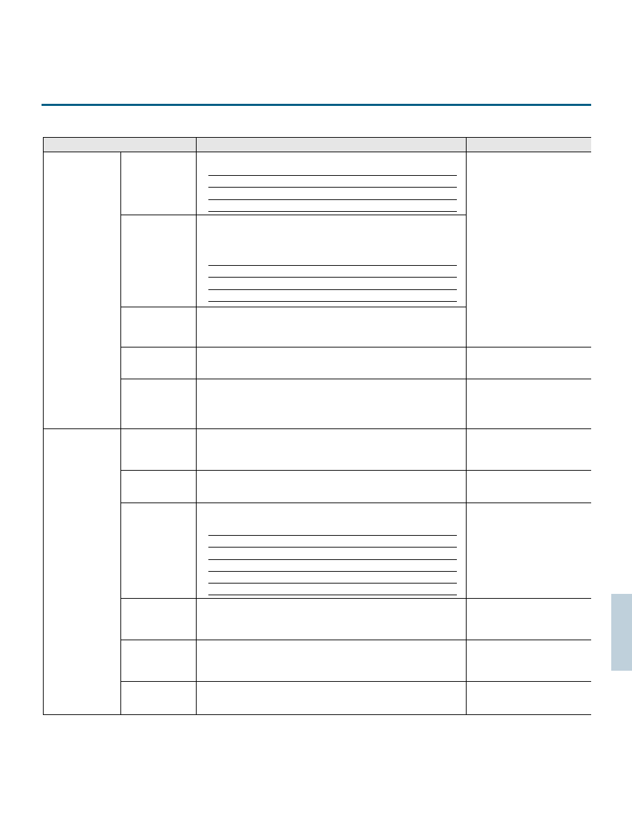
39
Reliability
ZENAMIC
Characteristics
Test Methods
Criterion
Robustness of
Terminations
(Tensile)
Robustness of
Terminations
(Bending)
Humidity
(Steady State)
Vibration
Solderability
Resistance to
Soldering Heat
High Temperature
Storage/Dry Heat
High Temperature
Load/
Dry Heat Load
Low Temperature
Storage/Cold
Damp Heat Load/
Humidity Load
Temperature
Cycle
Mechanical
Environmental
After gradual applying of the force specified below and keeping the unit fixed
for 10 seconds, the terminal shall be visually examined for any damage.
Terminal diameter Force
0.6mm, 0.8mm 9.8N(1.0kgf)
1.0mm 19.6N(2.0kgf)
The unit shall be secured with its terminal kept vertical and the force
specified below shall be applied in the axial direction.
The terminal shall gradually be bent by 90
in one direction, then 90
in the
opposite direction, and again back to the original position.
The damage of the terminal shall be visually examined.
After repeated applying of a single harmonic vibration (amplitude:0.75mm,
double amplitude:1.5mm) with 1 minute vibration frequency cycle (10 Hz to
55 Hz to 10Hz) to each of three perpendicular directions for 2 hours.
Thereafter, the unit shall be visually examined.
The specimen shall be subjected to 125 2 C for 1000 hours in a
thermostatic bath without load and then stored at room temperature and
normal humidity for 1 to 2 hours. Thereafter, the change of V
CmA
shall be
measured.
After being continuously applied the Maximum Allowable Voltage at 85
2 C for 1000 hours, the specimen shall be stored at room temperature and
normal humidity for 1 to 2 hours. Thereafter, the change of V
CmA
shall be
measured.
The specimen shall be subjected to 40 2 C, 90 to 95% RH for 1000 hours
without load and then stored at room temperature and normal humidity for 1
to 2 hours. Thereafter, the change of V
CmA
shall be measured.
The specimen shall be subjected to 40 2 C, 90 to 95% RH and the
Maximum Allowable Voltage for1000 hours and then stored at room
temperature and normal humidity for 1 to 2 hours. Thereafter, the change of
V
CmA
shall be measured.
The specimen shall be subjected to 40 2 C without load for1000 hours
and then stored at room temperature and normal humidity for 1 to 2 hours.
Thereafter, the change of V
CmA
shall be measured.
The following temperature cycle shall be repeated five times and then stored
at room temperature and normal humidity for 1 to 2 hours. The change of
V
CmA
and mechanical damage
shall be examined.
After each lead shall be dipped into a solder bath of 260 5 C to a point
2.0 to 2.5mm from the body of the unit, using shielding board (t 1.5mm),
be held there for 10 1s (5 series:5 1s) and then be stored at room
temperature and normal humidity for 1 to 2 hours.
The change of V
CmA
and mechanical damage shall be examined.
After dipping the terminals to a depth of approxirnately 3 mm from the body
in a soldering bath of 235 5 C for 2 0.5seconds, the terminal shall be
visually examined.
Terminal diameter Force
0.6mm, 0.8mm 4.9N(0.5kgf)
1.0mm 9.8N(1.0kgf)
Step Temperature( C) Period(minutes)
1 40 3 30 3
2 Room temperature 15 3
3 125 2 30 3
4 Room temperature 15 3
Approximately 95% of
the terminals shall be covered
uniformly with new solder
V
CmA
/V
CmA
5%
No remarkable
mechanical damage
No remarkable
mechanical damage
V
CmA
/V
CmA
5%
No remarkable
mechanical damage
V
CmA
/V
CmA
5%
V
CmA
/V
CmA
10%
V
CmA
/V
CmA
10%
V
CmA
/V
CmA
5%
V
CmA
/V
CmA
5%

40
GASTUBE
ARRESTER
Gas tube arrester(GTA)is a surge absorber
featuring low capacitance and high surge
absorption energy.
lt consists of a sealed tube in which inert
gas is injected and electrodes which are
set at fixed intervals. The simple structure
and the dimensional accuracy offer high
reliability and stabilized characteristics.
Applications
Maximum Single lmpulse Dischrge Current
Capacitance
Operating Temperature Range
DC Holdover Voltage
Impulse Waveform
1. Protection for telephone set, facsimile, telex,
telephone system, CATV, computer and peripheral
equipment.
2. Semiconductor circuit protection in equipment
that also uses high voltage such as TV,
oscilloscope, and electron microscope.
3. Automatic control of luminous energy in
stroboscopic tube.
4. Generator of high-voltage for gas igniter.
Voltage-Current Characteristics
Electrical Characteristics
AC Discharge Current
lmpulse Surge Life
lnsulation Resistance
DC Breakdown Voltage
Impulse Breakdown Voltage
The current through the GTA is changed over the
range of values of 10
18
to 10
2
amps which is shown
as the figure below and the voltage across the GTA will
also valy.The discharge characteristics are changed to
various mode by the flowing current, and the final
mode of the discharge characteristics is arc discharge .
When the applied voltage across the GTA exceeds
the breakdown voltage (sparkover voltage), the
current through the GTA increases rapidly to value
of several amps or greater. The rate of current rise and
level to be reached are limited by the series impedance
of the circuit.The voltage across the GTA at this
time is very low with typical value of 20 to 30 volts.
The current is the rms value of sinusoidal alternating
current of 50Hz or 60Hz which can flow through the
GTA in accordance with a certain test method without
substantially altering its sparkover voltage. The
usual test consists of specified loads applied for 1
sec at interval of 1 min alternately. ln the test of the
maximum AC discharge current, the GTA is applied
9 cycles of 50Hz AC(180 ms) continuously.
The life is defined as the minimum number of surges
of a certain current waveform the GTA can survive
without deterioration of its operating specifications.
This is defined as the resistance value across the
terminal of GTA at 100V
DC
for devices over 230V
DC
(140V
DC
for GTA type) breakdown voltage and 50V
DC
for devices less than 230V
DC
(140V
DC
for GTA type)
ratings.
The voltage is the minimum slowly rising DC voltage that
will cause sparkover when applied across the terminal
of the GTA.The GTA shall be placed in darkness for
at least 15 min and tested in this condition using a
ramp voltage waveform with 100V/s to 500V/s.
The GTA shall be tested with a positive and a
negative waveform. The sparkover current for DC
sparkover voltage test shall be within 10 amps.
The GTA to be exposed to the test shall be kept in
total darkness before (for at least 15 min) and during
the test. Then, with a ramp voltage with 5kV / s
applied to the GTA, the breakdown voltage level is
recorded. ln case of testing with opposite polarity,
using the same GTA, a minimum of 15 min shall
elapse.
This test is to determine the ability o f the GTA t o
conduct a maximum single impulse Discharge
current. The current impulse waveform is 8 / 20
s.
The maximum single impulse discharge current
is the crest
current of the impulse.
This values is defined as the maximum DC voltage
across the t erminals of the GTA which is expected
to clear and restore its high impedance state within
150 ms or less after the passage of a surge.
The capacitance of the GTA is defined as
capacitance across terminals of the GTA at 1 kHz.
20 C 65 C
lmpulse breakdown voltage is the voltage at which
the GTA fires when the voltage increases at rates
of more than 100V/ s. This value may not vary even
after the GTA has been stored in the dark for long
period. The value of the impulse breakdown voltage
increases with increasing steepness of the surge
voltage as the figure below.
Non self
sustaining
Townsent
Glow
Terminal voltage
b
c
d
a
e
f
g
Arc
1A
10
16
10
4
10
5
A
abnomalous
glow
100
90
50
10
Tf
Tt
Time ( s)
St
riking Voltage
V
V
T
D
D
D
R
R
Ro
Ro
C
C
loc
li
1
2
1. DC constant-voltage regulated power supply
2. lmpulse generator
: DC current adjustment resistor
: Line mimic resistor 136 Ohms
: Line mimic capacitor 0.083 F
: lnsulation diode
Current
A

41
Dimensions
GTA3P type
Dimensions
Specifications
Specifications
CM2P, CM3P type
Glass tube
0.45 Dumet wire
min.0.8
min.0.8
A
:
max.7.0
B
:
6.5
0.3
Unit (mm)
V-t Characteristics
A ceramic tube is sealed at both side by electrodes,
and inside of it is filled up by inert gas. The ceramic
type gas tube arrester has superior characteristics
such as mechanical strength, surge absorption
energy and stability. There are two electrodes type
and three electrodes type.
Ceramic tube
Dimensions A
90L
145L
230L
350L
470L
6.6 0.2
7.1 0.2
600L
800L
7.6 0.2
0.8 C.P. wire
0.8 C.P. wire
Electrodes
Ceramic tube
8
0.2
8
0.2
8
0.2
8
0.2
18 min.
11.7
0.2
Electrodes
Unit (mm)
Ceramic tube
11.7
0.2
6
0.5
6
0.5
24 min.
A
Ceramic tube
A
CM2P
CM2P type
CM3P type
CM3P
Leadless type
Leadless type
V-t Characteristics
2
1
3
4
5
6
2
1
20kV/
s
5kV/
s
1kV/
s
100V/
s
2kV/s
100V/s
3
4
5
6
100
10
200
300
400
500
700
1000
2000
4000
7
10
6
10
5
10
4
10
3
10
2
10
1
10
0
10
Response time (s)
1
10
2
10
3
Breakedown voltage (V)
GTA3P-400
GTA3P-350
2
1
3
4
5
6
2
1
20kV/
s
5kV/
s
1kV/
s
100V/
s
2kV/s
100V/s
3
4
5
6
100
10
200
300
400
500
700
1000
2000
4000
7
10
6
10
5
10
4
10
3
10
2
10
1
10
0
10
Response time (s)
1
10
2
10
3
Breakedown voltage (V)
CM2P-800L
CM2P-600L
CM2P-470L
CM2P-350L
CM2P-230L
CM2P-145L
CM2P-90L
25 min.
19 max.
B
A
CM2P-90L
CM2P-145L
CM2P-230L
CM2P-350L
CM2P-470L
CM2P-600L
CM2P-800L
CM3P-230L
CM3P-250L
CM3P-350L
CM3P-400L
90V 20%
145V 20%
230V 15%
350V 15%
470V 15%
600V 15%
800V 15%
230V 20%
250V 20%
350V 20%
400V 20%
1000V max.
1000V max.
1000V max.
1500V max.
1500V max.
1800V max.
2000V max.
1000V max.
1000V max.
1200V max.
1200V max.
Part No.
DC Breakdown
Voltage
(100V/s)
Impulse Breakdown
Voltage
(5kV/ s)
Maximum Single
Impulse Discharge
Current (8/20 s)
Insulation
Resistance
(DC100V or 50V)
Capacitance
(1kHz)
Impulse Life
(10/1000 s)
10000A 2 times
10000A 2 times
10000A 2 times
10000A 2 times
10000A 2 times
10000A 2 times
10000A 2 times
10000A 2 times
10000A 2 times
10000A 2 times
10000A 2 times
500A 600 times
500A 600 times
500A 600 times
500A 600 times
500A 600 times
500A 600 times
500A 600 times
500A 600 times
500A 600 times
500A 600 times
500A 600 times
10
4
M min.
10
4
M min.
10
4
M min.
10
4
M min.
10
4
M min.
10
4
M min.
10
4
M min.
10
4
M min.
10
4
M min.
10
4
M min.
10
4
M min.
2pF max.
2pF max.
2pF max.
2pF max.
2pF max.
2pF max.
2pF max.
2pF max.
2pF max.
2pF max.
2pF max.
GTA3P-350
GTA3P-400
350V 15%
400V 15%
1600V max.
1600V max.
Part No.
DC Breakdown
Voltage
(100V/s)
Impulse Breakdown
Voltage
(5kV/ s)
Maximum Single
Impulse Discharge
Current (8/20 s)
Insulation
Resistance
(DC100V )
Capacitance
(1kHz)
Impulse Life
(8/20 s)
1500A 1 time
350A 1000 times
10
4
M min
1pF max.
Suffix : L shows lead type and no-suffix shows leadless type
2
1
3
4
5
6
7
6
5
4
3
2
1
0
1
2
3
2
1
20kV/
s
5kV/
s
1kV/
s
100V/
s
2kV/s
100V/s
3
4
5
6
100
10
200
300
400
500
700
1000
2000
4000
10
10
10
10
10
10
10
10
Response time (s)
10
10
Breakedown voltage (V)
CM3P400(L)
CM3P350(L)
CM3P250(L)
CM3P230(L)
CM2P
CM3P
Lead type
Lead type
Lead less type
Lead less type
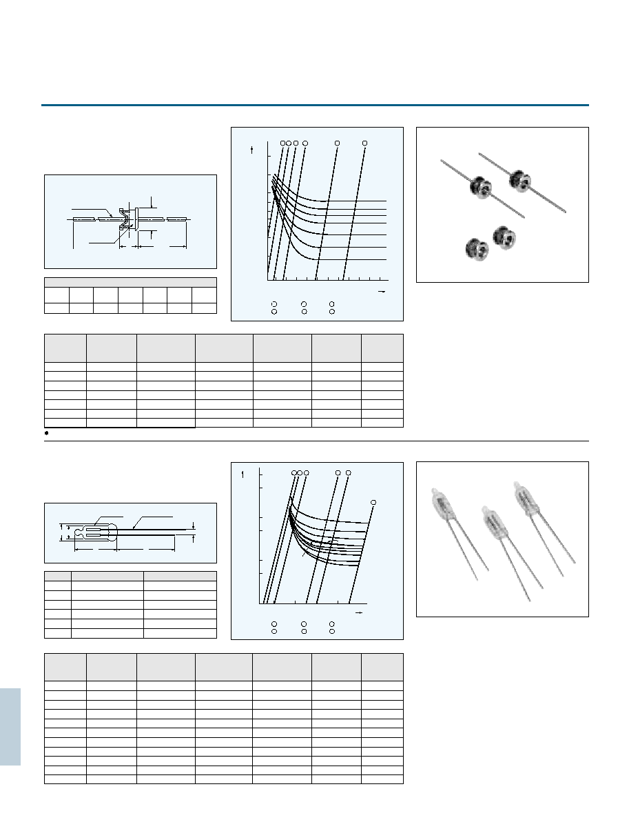
42
Dimensions
A glass tube is sealed at both side by electrodes, and
inside of it is filled up by inert gas.
M2P type
Dimensions
Specifications
Specifications
GTA type
Unit (mm)
Unit (mm)
Unit (mm)
Unit (mm)
Electrodes are set in a sealed glass, and inert gas is
filled inside.
2
1
3
4
5
6
2
1
20kV/ s
5kV/ s
1kV/ s
100V/ s
2kV/s
100V/s
3
4
5
6
V-t Characteristics
100
10
200
300
400
500
700
1000
2000
4000
7
10
6
10
5
10
4
10
3
10
2
10
1
10
0
10
Response time (s)
1
10
2
10
3
Breakedown voltage (V)
M2P-800L
M2P-600L
M2P-470L
M2P-350L
M2P-230L
M2P-145L
M2P-90L
GTA-750D
GTA-500D
GTA-350D
GTA-200D
GTA-230D
GTA-250D
GTA-170D
GTA-140D
GTA-100D
GTA-80D
0.8 C.P. wire
8.2
0.2
Glass tube
24 min.
A
2
1
3
4
5
6
2
1
20kV/ s
5kV/ s
1kV/ s
100V/s
100V/ s
2kV/s
3
4
5
6
V-t Characteristics
10
50
100
500
1000
5000
10000
10
2
10
4
10
6
10
8
Response time (s)
Breakedown voltage (V)
Dimension A
M2P-
90L
6.1 0.2
M2P-
145L
6.1 0.2
M2P-
230L
6.6 0.3
M2P-
350L
6.6 0.3
M2P-
470L
6.6 0.3
M2P-
600L
6.6 0.3
M2P-
800L
7.6 0.3
Glass tube
F : Dumet wire
C
D
B
E
A
A
B
C
D
E
F
GTA-80D GTA-500D
GTA-750D,800D
6.4max.
5.85 0.3
19max
25min.
3min.
0.45
7.0max.
6.5 0.3
19max
25min.
3min.
0.45
GTA-80D
GTA-100D
GTA-140D
GTA-170D
GTA-200D
GTA-230D
GTA-250D
GTA-350D
GTA-500D
GTA-750D
GTA-800D
80V 15%
100V 15%
140V 15%
170V 15%
200V 15%
230V 15%
250V 15%
350V 15%
500V 15%
750V 15%
800V 15%
1200V max.
1300V max.
1300V max.
1500V max.
1700V max.
1700V max.
1700V max.
2000V max.
2100V max.
4500V max.
5000V max.
Part No.
DC Breakdown
Voltage
(100V/s)
Impulse Breakdown
Voltage
(5kV/ s)
Maximum Single
Impulse Discharge
Current (8/20 s)
Insulation
Resistance
(DC100V or 50V)
Capacitance
(1kHz)
Impulse Life
(8/20 s)
1500A 1 time
1500A 1 time
1500A 1 time
1500A 1 time
1500A 1 time
1500A 1 time
1500A 1 time
1500A 1 time
1500A 1 time
1500A 1 time
1500A 1 time
500A 1000 times
500A 1000 times
500A 1000 times
500A 1000 times
500A 1000 times
500A 1000 times
500A 1000 times
500A 1000 times
500A 1000 times
500A 1000 times
500A 1000 times
10
4
M min.
10
4
M min.
10
4
M min.
10
4
M min.
10
4
M min.
10
4
M min.
10
4
M min.
10
4
M min.
10
4
M min.
10
4
M min.
10
4
M min.
2pF max.
2pF max.
2pF max.
2pF max.
2pF max.
2pF max.
2pF max.
2pF max.
2pF max.
2pF max.
2pF max.
M2P-90L
M2P-145L
M2P-230L
M2P-350L
M2P-470L
M2P-600L
M2P-800L
90V 20%
145V 20%
230V 15%
350V 15%
470V 15%
600V 15%
800V 15%
1000V max.
1000V max.
1000V max.
1500V max.
1500V max.
2500V max.
2500V max.
Part No.
DC Breakdown
Voltage
(100V/s)
Impulse Breakdown
Voltage
(5kV/ s)
Maximum Single
Impulse Discharge
Current(8/20 s)
Insulation
Resistance
(DC100V or 50V)
Capacitance
(1kHz)
Impulse Life
(10/1000 s)
3000A 2 times
3000A 2 times
3000A 2 times
3000A 2 times
3000A 2 times
3000A 2 times
3000A 2 times
500A 100 times
500A 100 times
500A 100 times
500A 100 times
500A 100 times
500A 100 times
500A 100 times
10
4
M min.
10
4
M min.
10
4
M min.
10
4
M min.
10
4
M min.
10
4
M min.
10
4
M min.
2pF max.
2pF max.
2pF max.
2pF max.
2pF max.
2pF max.
2pF max.
Suffix : shows lead type and no-suffix shows leadless type
Lead type
Lead less type

43
Specifications
SA01-401
SA01-501
SA01-242
SA01-302
SA01-362
400V %
500V %
2400V %
3000V %
3600V %
1000V max.
1400V max.
4000V max.
4500V max.
5000V max.
AC125V (Line-Line)
AC250V (Line-Line)
AC125V (Line-GND)
AC250V (Line-GND)
AC250V (Line-GND)
AC1200V 3s
AC1500V 1min
AC1800V 3s
Part No.
DC Breakdown
Voltage
(100V/s)
Impulse Breakdown
Voltage
(5kV/ s)
Maximum Single
Impulse Discharge
Current(8/20 s)
Insulation
Resistance
(DC100V)
Capacitance
(1kHz)
Connection
Dielectric
Withstanding
Voltage
Impulse Life
(8/20 s)
SA01 type
The SA01 is a new product which can be utilized
for protecting transient voltage in power supply of
equipment with earth terminal.
For the equipment in which SA01 is used, the AC
withstanding voltage between power lines and earth
terminal can be tested without taking off "SA01".
1250A 2 times
1250A 2 times
1250A 2 times
1250A 2 times
1250A 2 times
100A 300 times
100A 300 times
100A 300 times
100A 300 times
100A 300 times
10
2
M min
10
2
M min
10
2
M min
10
2
M min
10
2
M min
2pF max.
2pF max.
2pF max.
2pF max.
2pF max.
Safety Standards
Application Circuit
Dimensions
Standards Name
Standards No.
File No.
Mark
UL
UL1449
E128417
CSA
C22.2 No.1
LR-76099
TUV
IEC61051
J500/5463
0.6 Tinned
copper leads
0.6 Solderplated
nickel leads
10 1
10 1
18 1
SA01-401
27
16
1
15
1
13min.
Unit (mm)
EQUIPMENT
SA01
2
2
SA01
1
1
2
1
CIRCUIT
AC100V
or
AC200V
GND
AC100V
:
SA01-401 SA01-242
AC200V
:
SA01-501 SA01-302 or SA01-362
30
20
30
20
30
20
30
20
30
20

WARRANTY
USA:SEMITEC USA CORP.
TEL:1-631-587-4086 FAX:1-631-321-9604
E-mail : sales@semitec-usa.com
HONG KONG:SEMITEC(H.K.)CO.,LTD. TEL:852-2369-6773 FAX:852-2739-2396
E-mail : semihk@netvigator.com
TAIWAN:SEMITEC TAIWAN CORP.
TEL:886-2-2509-9855 FAX:886-2-2509-9599
E-mail : semitec@ms24.hinet.net
UK:ATC SEMITEC LTD.
TEL:44-1565-750538 FAX:44-1565-652396
E-mail : sales@atcsemitec.co.uk
KOREA:SEMITEC KOREA CO.,LTD.
TEL:82-2-3281-1155 FAX:82-2-3281-3338
E-mail : semitec@kornet.net
CHINA:SEMITEC SHANGHAI OFFICE
TEL:86-21-53086000 FAX:86-21-33040188
E-mail : xsgsxh@public.tz.js.cn
The manufacturer hereby warrants, that it will replace this product
or any part thereof which shall prove to be defective in workman-
ship or material, subject to the following limitations:
This is only for the benefit of the original purchaser and to no
other person, company or individual.
This warranty does not apply to defects caused by improper
installation.
This warranty is limited to the replacement of the defective
product, or part thereof, and does not include any labor costs for
installation or removal of the product.
The manufacturer shall not be liable for indirect,
consequential or special damages and is limited solely to
replacement of the product.
lf the product or any part thereof shall prove to be defective in
workmanship or material, the original purchaser shall ship the
product to the manufacturer in the original packing carton, together
with a copy of the original sales receipt for the product, and, if in the
opinion of the manufacturer, the product proves to be defective in
workmanship or material, the sole obligation of the manufacturer
shall be the replacement of the defective product or part thereof.
Shipping charges to the manufacturer is the obligation of the
original purchaser.
This limited warranty is in lieu of and replaces all of the warranties
previously given by the manufacturer, both express and implied, in-
cluding any warranties of merchantability or fitness for a particular
purpose. There are no warranties which extend beyond the face
hereof.
No lawsuit may be commenced against the manufacturer unless
the original consumer purchaser has complied with all of the terms
and conditions of this warranty and the manufacturer has refused
to comply therewith.
(02.9.3K)
Subject to change without notice.
HEAD OFFICE:7-7, Kinshi 1-Chome, Sumida-ku, Tokyo, 130-8512 Japan
V isit us on the Web at
http://www.semitec.co.jp/
TEL:81-3-3621-2704 FAX:81-3-3623-6815
E-mail : overseas@mail.semitec.co.jp
(1)
(2)
(3)
(4)
ISO9002 ISO14001 Certified
SEMITEC GROUP