 | –≠–ª–µ–∫—Ç—Ä–æ–Ω–Ω—ã–π –∫–æ–º–ø–æ–Ω–µ–Ω—Ç: 118AHT | –°–∫–∞—á–∞—Ç—å:  PDF PDF  ZIP ZIP |

DATA SHEET
Product specification
Supersedes data of 11th December 2001
File under BCcomponents, BC01
2002 Jun 07
BCcomponents
118 AHT
Aluminum electrolytic capacitors
Axial High Temperature

2002 Jun 07
2
BCcomponents
Product specification
Aluminum electrolytic capacitors
Axial High Temperature
118 AHT
FEATURES
∑
Polarized aluminum electrolytic
capacitors, non-solid electrolyte
∑
Axial leads, cylindrical aluminium
case, insulated with a blue sleeve
∑
Mounting ring version not insulated
∑
Taped versions up to case
15
◊
30 mm available for
automatic insertion
∑
Charge and discharge proof
∑
Extra long useful life:
up to 8000 hours at 125
∞
C,
high reliability
∑
Extended temperature range: 125
∞
C
(usable up to 150
∞
C)
∑
Miniaturized, high CV-product per
unit volume.
Fig.1 Component outlines; Forms BR and BA.
MBB121
118 AHT
125
∞
C
119 AHT-DIN
138 AML
high ripple,
low impedance
CCB050
105
∞
C
120 ATC
125
∞
C
very high
ripple
APPLICATIONS
∑
Automotive, industrial and
telecommunication
∑
Smoothing, filtering, coupling,
decoupling, timing
∑
For use after very long storage
(10 years) without voltage applied
∑
Portable and mobile equipment
(small size, low mass)
∑
Low mounting height boards,
vibration and shock resistant
∑
Outdoor applications,
e.g. aerial amplifiers.
QUICK REFERENCE DATA
DESCRIPTION
VALUE
Case sizes (
D
nom
◊
L
nom
in mm)
6.5
◊
18 to 10
◊
25
10
◊
30 to 21
◊
38
Rated capacitance range, C
R
1 to 10000
µ
F
Tolerance on C
R
±
20%
Rated voltage range, U
R
6.3 to 200 V
Category temperature range
-
40 to +125
∞
C
-
55 to +125
∞
C
Endurance test at 150
∞
C (6.3 to 100 V)
500 hours
500 hours
Endurance test at 125
∞
C
2000 hours
3000 hours
Useful life at 125
∞
C
4000 hours
8000 hours
Useful life at 40
∞
C, 1.8
◊
I
R
applied
500000 hours
1000000 hours
Shelf life at 0 V, 125
∞
C:
U
R
= 6.3 to 63 V
500 hours
U
R
= 100 and 200 V
100 hours
Based on sectional specification
IEC 60384-4/EN130300
Climatic category IEC 60068
40/125/56
55/125/56

2002 Jun 07
3
BCcomponents
Product specification
Aluminum electrolytic capacitors
Axial High Temperature
118 AHT
Selection chart for C
R
, U
R
and relevant nominal case sizes (
D
◊
L in mm)
Preferred types in bold.
C
R
(
µ
F)
U
R
(V)
6.3
10
16
25
40
63
100
200
1.0
-
-
-
-
-
6.5
◊
18
-
-
2.2
-
-
-
-
-
6.5
◊
18
-
-
4.7
-
-
-
-
-
6.5
◊
18
6.5
◊
18
8
◊
18
10
-
-
-
-
-
6.5
◊
18
6.5
◊
18
10
◊
25
15
-
-
-
-
-
-
-
10
◊
30
22
-
-
-
-
-
6.5
◊
18
8
◊
18
12.5
◊
30
33
-
-
-
-
-
-
10
◊
25
15
◊
30
47
-
-
-
-
6.5
◊
18
8
◊
18
10
◊
25
18
◊
30
-
-
-
-
-
-
10
◊
30
-
68
-
-
-
-
-
-
12.5
◊
30
-
100
-
-
-
6.5
◊
18
8
◊
18
10
◊
25
12.5
◊
30
21
◊
38
-
-
-
-
-
10
◊
30
-
-
150
-
-
-
-
10
◊
18
12.5
◊
30
-
-
220
-
6.5
◊
18
8
◊
18
10
◊
18
10
◊
25
12.5
◊
30
18
◊
30
-
-
-
-
-
10
◊
30
-
-
-
330
-
8
◊
18
-
-
12.5
◊
30
-
-
-
470
-
8
◊
18
10
◊
18
10
◊
25
12.5
◊
30
18
◊
30
21
◊
38
-
-
-
-
10
◊
30
-
-
-
-
680
-
-
-
12.5
◊
30
-
-
-
-
1000
10
◊
18
10
◊
25
12.5
◊
30
12.5
◊
30
18
◊
30
21
◊
38
-
-
-
10
◊
30
-
-
-
-
-
-
1500
10
◊
25
12.5
◊
30
12.5
◊
30
15
◊
30
18
◊
38
-
-
-
2200
-
12.5
◊
30
15
◊
30
18
◊
30
21
◊
38
-
-
-
3300
-
15
◊
30
18
◊
30
18
◊
38
-
-
-
-
4700
-
18
◊
30
18
◊
38
21
◊
38
-
-
-
-
6800
-
18
◊
38
21
◊
38
-
-
-
-
-
10000
-
21
◊
38
-
-
-
-
-
-

2002 Jun 07
4
BCcomponents
Product specification
Aluminum electrolytic capacitors
Axial High Temperature
118 AHT
MECHANICAL DATA, AVAILABLE FORMS AND PACKAGING QUANTITIES
Fig.2 Dimensional outline; Forms BA and BR.
Dimensions in mm.
Form BR: Taped on reel,
case
D
◊
L = 6.5
◊
18 to 15
◊
30 mm.
Form BA: Taped in box (ammopack),
case
D
◊
L = 6.5
◊
18 to 10
◊
25 mm.
For dimensions see Table
1
.
Tape dimensions are specified in data handbook BC01, section "Packaging".
MBC193 - 1
73 1.6
L
D
d
O
O
F
+
Fig.3 Dimensional outline; Form AA.
Dimensions in mm.
Form AA: Axial in box,
case
D
◊
L = 10
◊
30 to 21
◊
38 mm.
For dimensions see Table 1.
CCB086
D
33
±
1
L
l
d
F

2002 Jun 07
5
BCcomponents
Product specification
Aluminum electrolytic capacitors
Axial High Temperature
118 AHT
Table 1
Axial; physical dimensions, mass and packaging quantities; see Figs 2 and 3
Table 2
Mounting ring; physical dimensions, mass and packaging quantities; see Fig.4
NOMINAL
CASE SIZE
D
◊
L
(mm)
CASE
CODE
AXIAL: FORM AA, BA and BR
MASS
(g)
PACKAGING QUANTITIES
d
(mm)
I
(mm)
D
max
(mm)
L
max
(mm)
F
min
(mm)
FORM
AA
FORM
BA
FORM
BR
6.5
◊
18
4
0.8
-
6.9
18.5
25
1.3
-
1000
1000
8
◊
18
5
0.8
-
8.5
18.5
25
1.7
-
500
500
10
◊
18
6
0.8
-
10.5
18.5
25
2.5
-
500
500
10
◊
25
7
0.8
-
10.5
25.0
30
3.3
-
500
500
10
◊
30
00
0.8
55
±
1
10.5
30.5
35
4.8
200
-
500
12.5
◊
30
01
0.8
55
±
1
13.0
30.5
35
7.4
200
-
400
15
◊
30
02
0.8
55
±
1
15.5
30.5
35
11.7
200
-
250
18
◊
30
03
0.8
55
±
1
18.5
30.5
35
12.9
200
-
-
18
◊
38
04
0.8
34
±
1
18.5
39.0
44
19.0
100
-
-
21
◊
38
05
0.8
34
±
1
21.5
39.0
44
24.0
100
-
-
NOMINAL
CASE SIZE
D
◊
L
(mm)
CASE
CODE
MOUNTING RING: FORM MR
MASS
(g)
PACKAGING
QUANTITIES
d1
(mm)
d2
(mm)
D
max
(mm)
D2
max
(mm)
D3
(mm)
L
max
(mm)
15
◊
30
02
0.8
1.0 +0.4
15.5
17.5
16.5
±
0.2
33
8.6
200
18
◊
30
03
0.8
1.0 +0.4
18.5
19.5
18.5
±
0.2
33
11.5
200
18
◊
38
04
0.8
1.0 +0.4
18.5
19.5
18.5
±
0.2
42
14.0
100
21
◊
38
05
0.8
1.0 +0.4
21.5
22.5
21.5
±
0.2
42
19.0
100
D3
d2
120
∞
(3
◊
)
CCB063
D
L
D2
d1
90
∞ ±
2
∞
(3
◊
)
mounting holes
1.3
+
0.1
0
(3
◊
)
3.6
+
0.2
-
0.4
1
+
1.0
-
0.5
1.05
+
0.03
-
0.1
(3
◊
)
1.3
0
-
0.05
(3
◊
)
Fig.4 Mounting hole diagram and outline; Form MR; mounting ring and pins.
Dimensions in mm.
Form MR: case
D
◊
L = 15
◊
30 to 21
◊
38 mm.
Case not insulated (insulation on request).
Especially for applications with severe shocks and vibrations.
For dimensions see Table 2.

2002 J
un 07
6
B
C
com
ponent
s
Pr
oduct
spec
i
f
i
c
at
i
o
n
Alu
m
inu
m
electroly
t
ic c
apaci
t
or
s
Axial Hi
gh T
emperature
11
8
AHT
ELECTRICAL DATA AND ORDERING INFORMATION
Unless otherwise specified, all electrical values in Table 3 apply at T
amb
= 20
∞
C,
P = 86 to 106 kPa, RH = 45 to 75%.
C
R
rated capacitance at 100 Hz, tolerance
±
20%
I
R
rated RMS ripple current at 100 Hz, 125
∞
C
I
L1
max. leakage current after 1 minute at U
R
I
L5
max. leakage current after 5 minutes at U
R
Tan
max. dissipation factor at 100 Hz
ESR
equivalent series resistance at 100 Hz (calculated from tan
max
and C
R
)
Z
max. impedance at 10 kHz
Ordering example
Electrolytic capacitor 118 series
1000
µ
F/10 V;
±
20%
Nominal case size:
10
◊
30 mm; Form BR
Catalogue number: 2222 118 24102.
Table 3
Electrical data and ordering information; preferred types in bold
U
R
(V)
C
R
100 Hz
(
µ
F)
NOMINAL
CASE SIZE
D
◊
L
(mm)
CASE
CODE
I
R
100 Hz
125
∞
C
(mA)
I
L1
1 min
(
µ
A)
I
L5
5 min
(
µ
A)
Tan
100 Hz
ESR
100 Hz
(
)
Z
10 kHz
(
)
CATALOGUE NUMBER 2222 ... .....
IN BOX
FORM AA
TAPED ON
REEL
FORM BR
TAPED IN
BOX
FORM BA
MOUNTING
RING
FORM MR
6.3
1000
10
◊
18
6
251
42
17
0.50
0.79
0.8
-
118 23102
118 33102
-
1500
10
◊
25
7
352
61
23
0.50
0.53
0.53
-
118 90502
118 90503
-
10
220
6.5
◊
18
4
109
20
8.4
0.35
2.53
2.1
-
118 24221
118 34221
-
330
8
◊
18
5
150
24
11
0.35
1.69
1.4
-
118 24331
118 34331
-
470
8
◊
18
5
179
32
13
0.35
1.19
1.0
-
118 24471
118 34471
-
1000
10
◊
25
7
343
64
24
0.35
0.56
0.55
-
118 90504
118 90505
-
1000
10
◊
30
00
550
64
24
0.32
0.505
0.45
118 14102
118 24102
-
-
1500
12.5
◊
30
01
740
94
34
0.32
0.340
0.28
118 14152
118 24152
-
-
2200
12.5
◊
30
01
830
136
48
0.40
0.290
0.27
118 14222
118 24222
-
-
3300
15
◊
30
02
1070
202
70
0.40
0.190
0.18
118 14332
118 24332
-
118 44332
4700
18
◊
30
03
1350
2 86
98
0.46
0.155
0.15
118 14472
-
-
118 44472
6800
18
◊
38
04
1730
412
140
0.53
0.100
0.10
118 14682
-
-
118 44682
10000
21
◊
38
05
1860
604
200
0.53
0.084
0.10
118 14103
-
-
118 44103
16
220
8
◊
18
5
145
25
11
0.25
1.81
1.5
-
118 25221
118 35221
-
330
10
◊
18
6
204
36
15
0.25
1.21
1.2
-
118 25331
118 35331
-
470
10
◊
18
6
243
49
19
0.25
0.85
0.83
-
118 25471
118 35471
-
680
10
◊
30
00
510
69
30
0.22
0.525
0.45
118 15681
118 25681
-
-

2002 J
un 07
7
B
C
com
ponent
s
Pr
oduct
spec
i
f
i
c
at
i
o
n
Alu
m
inu
m
electroly
t
ic c
apaci
t
or
s
Axial Hi
gh T
emperature
11
8
AHT
16
1000
12.5
◊
30
01
720
100
36
0.22
0.345
0.28
118 15102
118 25102
-
-
1500
12.5
◊
30
01
790
148
52
0.29
0.305
0.27
118 15152
118 25152
-
-
2200
15
◊
30
02
1010
215
74
0.29
0.205
0.18
118 15222
118 25222
-
118 45222
3300
18
◊
30
03
1300
321
110
0.34
0.165
0.15
118 15332
-
-
118 45332
4700
18
◊
38
04
1670
455
150
0.34
0.105
0.10
118 15472
-
-
118 45472
6800
21
◊
38
05
1790
657
220
0.38
0.088
0.10
118 15682
-
-
118 45682
25
100
6.5
◊
18
4
102
20
9
0.18
2.86
2.3
-
118 26101
118 36101
-
220
10
◊
18
6
196
37
15
0.18
1.30
1.25
-
118 26221
118 36221
-
330
10
◊
25
7
274
54
21
0.18
0.87
0.82
-
118 26331
118 36331
-
470
10
◊
25
7
327
75
28
0.18
0.61
0.57
-
118 90508
118 90509
-
470
10
◊
30
00
490
75
28
0.18
0.61
0.50
118 16471
118 26471
-
-
680
12.5
◊
30
01
680
106
38
0.18
0.42
0.30
118 16681
118 26681
-
-
1000
12.5
◊
30
01
760
154
54
0.24
0.375
0.28
118 16102
118 26102
-
-
1500
15
◊
30
02
980
229
79
0.25
0.263
0.22
118 16152
118 26152
-
118 46152
2200
18
◊
30
03
1240
334
110
0.26
0.185
0.17
118 16222
-
-
118 46222
3300
18
◊
38
04
1610
499
170
0.26
0.12
0.11
118 16332
-
-
118 46332
4700
21
◊
38
05
1710
709
240
0.28
0.095
0.10
118 16472
-
-
118 46472
40
47
6.5
◊
18
4
89.8
20
7.8
0.11
3.72
2.8
-
118 27479
118 37479
-
100
8
◊
18
5
147
28
12
0.11
1.75
1.3
-
118 27101
118 37101
-
150
10
◊
18
6
207
40
16
0.11
1.17
1.0
-
118 27151
118 37151
-
220
10
◊
25
7
287
57
22
0.11
0.80
0.68
-
118 90511
118 90512
-
220
10
◊
30
00
390
57
22
0.10
0.70
0.55
118 17221
118 27221
-
-
330
12.5
◊
30
01
570
83
30
0.10
0.43
0.33
118 17331
118 27331
-
-
470
12.5
◊
30
01
620
117
42
0.11
0.38
0.30
118 17471
118 27471
-
-
680
15
◊
30
02
810
167
58
0.11
0.255
0.23
118 17681
118 27681
-
118 47681
1000
18
◊
30
03
1070
244
84
0.13
0.205
0.18
118 17102
-
-
118 47102
1500
18
◊
38
04
1390
364
120
0.13
0.13
0.11
118 17152
-
-
118 47152
2200
21
◊
38
05
1540
532
180
0.15
0.105
0.10
118 17222
-
-
118 47222
U
R
(V)
C
R
100 Hz
(
µ
F)
NOMINAL
CASE SIZE
D
◊
L
(mm)
CASE
CODE
I
R
100 Hz
125
∞
C
(mA)
I
L1
1 min
(
µ
A)
I
L5
5 min
(
µ
A)
Tan
100 Hz
ESR
100 Hz
(
)
Z
10 kHz
(
)
CATALOGUE NUMBER 2222 ... .....
IN BOX
FORM AA
TAPED ON
REEL
FORM BR
TAPED IN
BOX
FORM BA
MOUNTING
RING
FORM MR

2002 J
un 07
8
B
C
com
ponent
s
Pr
oduct
spec
i
f
i
c
at
i
o
n
Alu
m
inu
m
electroly
t
ic c
apaci
t
or
s
Axial Hi
gh T
emperature
11
8
AHT
63
1.0
6.5
◊
18
4
16.4
20
4.1
0.07
110
22
-
118 28108
118 38108
-
2.2
6.5
◊
18
4
24.3
20
4.3
0.07
51
15
-
118 28228
118 38228
-
4.7
6.5
◊
18
4
35.6
20
4.6
0.07
24
8.9
-
118 28478
118 38478
-
10
6.5
◊
18
4
51.9
20
5.3
0.07
11
5.6
-
118 28109
118 38109
-
22
6.5
◊
18
4
77.0
20
6.8
0.07
5.1
3.2
-
118 28229
118 38229
-
47
8
◊
18
5
126
22
9.9
0.07
2.4
1.5
-
118 28479
118 38479
-
100
10
◊
25
7
243
42
17
0.07
1.1
0.7
-
118 90513
118 90514
-
100
10
◊
30
00
340
42
17
0.07
1.91
1.62
118 18101
118 28101
-
-
150
12.5
◊
30
01
490
61
23
0.07
1.00
0.79
118 18151
118 28151
-
-
220
12.5
◊
30
01
550
87
32
0.08
0.94
0.82
118 18221
118 28221
-
-
330
15
◊
30
02
730
129
46
0.09
0.63
0.56
118 18331
118 28331
-
118 48331
470
18
◊
30
03
970
182
63
0.09
0.44
0.39
118 18471
-
-
118 48471
680
18
◊
38
04
1230
261
90
0.09
0.30
0.26
118 18681
-
-
118 48681
1000
21
◊
38
05
1400
383
130
0.10
0.16
0.20
118 18102
-
-
118 48102
100
4.7
6.5
◊
18
4
36
20
4.9
0.07
24
19
-
118 29478
118 39478
-
10
6.5
◊
18
4
52
20
6.0
0.07
11
9.0
-
118 29109
118 39109
-
22
8
◊
18
5
91
20
8.4
0.07
5.1
4.0
-
118 29229
118 39229
-
33
10
◊
25
7
140
24
11
0.07
3.4
2.7
-
118 29339
118 39339
-
47
10
◊
25
7
170
33
13
0.07
2.6
2.0
-
118 90535
118 90536
-
47
10
◊
30
00
240
33
13
0.08
2.6
2.0
118 19479
118 29479
-
-
68
12.5
◊
30
01
320
45
18
0.08
1.8
1.2
118 19689
118 29689
-
-
100
12.5
◊
30
01
380
64
24
0.09
1.4
1.15
118 19101
118 29101
-
-
150
15
◊
30
02
500
94
34
0.10
0.94
0.78
118 19151
118 29151
-
118 49151
220
18
◊
30
03
690
136
48
0.10
0.66
0.55
118 19221
-
-
118 49221
330
18
◊
38
04
890
202
70
0.10
0.45
0.37
118 19331
-
-
118 49331
470
21
◊
38
05
1050
286
98
0.10
0.33
0.28
118 19471
-
-
118 49471
U
R
(V)
C
R
100 Hz
(
µ
F)
NOMINAL
CASE SIZE
D
◊
L
(mm)
CASE
CODE
I
R
100 Hz
125
∞
C
(mA)
I
L1
1 min
(
µ
A)
I
L5
5 min
(
µ
A)
Tan
100 Hz
ESR
100 Hz
(
)
Z
10 kHz
(
)
CATALOGUE NUMBER 2222 ... .....
IN BOX
FORM AA
TAPED ON
REEL
FORM BR
TAPED IN
BOX
FORM BA
MOUNTING
RING
FORM MR

2002 J
un 07
9
B
C
com
ponent
s
Pr
oduct
spec
i
f
i
c
at
i
o
n
Alu
m
inu
m
electroly
t
ic c
apaci
t
or
s
Axial Hi
gh T
emperature
11
8
AHT
200
2.2
6.5
◊
18
4
27
20
4.9
0.06
44
23
-
118 90537
118 90538
-
4.7
8
◊
18
5
46
20
5.9
0.06
21
11
-
118 90539
118 90541
-
10
10
◊
25
7
85
20
8.0
0.06
9.4
5.0
-
118 90542
118 90543
-
15
10
◊
30
00
150
22
10
0.046
4.76
3.75
118 92159
118 90012
-
-
22
12.5
◊
30
01
210
31
13
0.046
3.17
2.22
118 92229
118 90013
-
-
33
15
◊
30
02
290
44
17
0.046
2.11
1.11
118 92339
118 90014
-
118 90002
47
18
◊
30
03
390
61
23
0.046
1.48
0.60
118 92479
-
-
118 90003
68
18
◊
38
04
500
86
31
0.046
1.02
0.42
118 92689
-
-
118 90004
100
21
◊
38
05
610
124
44
0.046
0.96
0.39
118 92101
-
-
118 90005
U
R
(V)
C
R
100 Hz
(
µ
F)
NOMINAL
CASE SIZE
D
◊
L
(mm)
CASE
CODE
I
R
100 Hz
125
∞
C
(mA)
I
L1
1 min
(
µ
A)
I
L5
5 min
(
µ
A)
Tan
100 Hz
ESR
100 Hz
(
)
Z
10 kHz
(
)
CATALOGUE NUMBER 2222 ... .....
IN BOX
FORM AA
TAPED ON
REEL
FORM BR
TAPED IN
BOX
FORM BA
MOUNTING
RING
FORM MR
2002 Jun 07
10
BCcomponents
Product specification
Aluminum electrolytic capacitors
Axial High Temperature
118 AHT
Additional electrical data
Table 4
Uprating values at reduced ambient temperature; note 1
Note
1. For applications at ambient temperatures of
85
∞
C, the rated voltage (U
R
) may be raised to U
R2
.
MARKING
The capacitors are marked (where possible) with the following information:
∑
Rated capacitance (in
µ
F)
∑
Tolerance on rated capacitance, code letter in accordance with "IEC 60062"
∑
Rated voltage (in V) at 125
∞
C and 85
∞
C
∑
Group number (118)
∑
Name of manufacturer
∑
Date code, in accordance with "IEC 60062"
∑
Code indicating factory of origin
∑
Band to identify the negative terminal
∑
`+' sign to identify the positive terminal.
PARAMETER
CONDITIONS
VALUE
AXIAL
MOUNTING RING
Voltage
Surge voltage
U
s
1.15
◊
U
R
Reverse voltage
U
rev
1 V
Current
Leakage current
after 1 minute at U
R
I
L1
0.006C
R
◊
U
R
+ 4
µ
A or 20
µ
A
(whichever is greater)
after 5 minutes at U
R
I
L5
0.002C
R
◊
U
R
+ 4
µ
A
Inductance
Equivalent series inductance (ESL)
case
D
◊
L mm:
6.5
◊
18
typ. 15 nH
-
8
◊
18
typ. 35 nH
-
10
◊
18
typ. 69 nH
-
10
◊
25
typ. 38 nH
-
10
◊
30
typ. 38 nH
-
12.5
◊
30
typ. 46 nH
-
15
◊
30
typ. 48 nH
typ. 39 nH
18
◊
30
typ. 50 nH
typ. 39 nH
18
◊
38
typ. 54 nH
typ. 39 nH
21
◊
38
typ. 59 nH
typ. 39 nH
SYMBOL
CONDITIONS
VALUES
UNIT
U
R
T
amb
> 85 to 125
∞
C
6.3
10
16
25
40
63
100
200
V
U
R2
T
amb
85
∞
C
10
16
25
40
63
100
125
250
V
2002 Jun 07
11
BCcomponents
Product specification
Aluminum electrolytic capacitors
Axial High Temperature
118 AHT
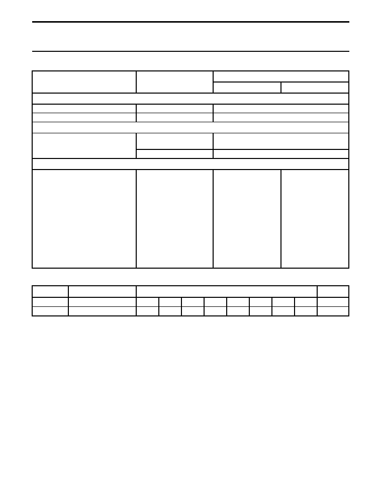
Capacitance (C)
Fig.5 Typical multiplier of capacitance as a function of ambient temperature.
Curve 1: 63 V.
Curve 2: 6.3 V.
C
0
= capacitance at 20
∞
C, 100 Hz.
Case
D
◊
L = 6.5
◊
18 to 10
◊
25 mm.
MGB228
0
50
100
1
10
10
50
Tamb ( C)
o
ESR 0
ESR
1
2
2
10
1
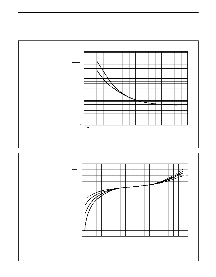
Fig.6 Typical multiplier of capacitance as a function of ambient temperature.
Curve 1: 100 V; 200 V.
Curve 2: 40 V; 63 V.
Curve 3: 16 V; 25 V.
Curve 4: 6.3 V; 10 V.
C
0
= capacitance at 20
∞
C, 100 Hz.
Case
D
◊
L = 10
◊
30 to 21
◊
38 mm.
60
0
20
MGB239
40
40
60
80
T amb ( C)
o
0.6
0.7
0.8
0.9
1.0
1.1
100
160
1.2
20
120
140
3
4
4
C
0
C
1
2
1

2002 Jun 07
12
BCcomponents
Product specification
Aluminum electrolytic capacitors
Axial High Temperature
118 AHT
Fig.7 Typical multiplier of capacitance as a function of frequency.
Curve 1: 63 V to 200 V (
<
15
µ
F).
Curve 2: 63 V; 100 V (
15
µ
F).
Curve 3: 40 V.
Curve 4: 25 V.
Curve 5: 16 V.
Curve 6: 10 V.
Curve 7: 6.3 V.
C
0
= capacitance at 20
∞
C; 100 Hz.
Case
D
◊
L = 6.5
◊
18 to 10
◊
25 mm.
0
10
5
MGB240
10
4
10
3
10
2
10
f (Hz)
0.2
0.4
0.6
0.8
1.0
1.2
1
4
5
6
7
C
0
C
2
3
Fig.8 Typical multiplier of capacitance as a function of frequency.
Curve 1: 200 V.
Curve 2: 100 V.
Curve 3: 63 V.
Curve 4: 40 V.
Curve 5: 25 V.
Curve 6: 16 V.
Curve 7: 10 V.
Curve 8: 6.3 V.
C
0
= capacitance at 20
∞
C; 100 Hz.
Case
D
◊
L = 10
◊
30 to 21
◊
38 mm.
0.5
10
4
MGB241
10
3
10
2
10
f (Hz)
0.6
0.7
0.8
0.9
1.0
1.1
1
8
C
0
C
1
2
3
4
5
6
7
8

2002 Jun 07
13
BCcomponents
Product specification
Aluminum electrolytic capacitors
Axial High Temperature
118 AHT
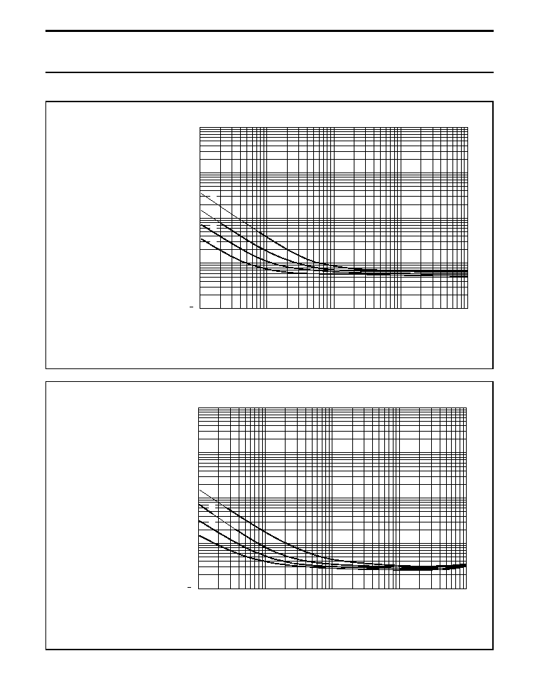
Equivalent series resistance (ESR)
Curve 1: 100 V; 200 V.
Curve 2: 25 V; 40 V; 63 V.
Curve 3: 6.3 V; 10 V; 16 V.
ESR
0
= typical at 20
∞
C; 100 Hz.
Case
D
◊
L = 6.5
◊
18 to 15
◊
30 mm.
Fig.9 Typical multiplier of ESR as a function of ambient temperature.
MGB242
0
150
50
100
1
10
50
100
Tamb ( C)
o
ESR 0
ESR
10
2
10
1
1
2
3
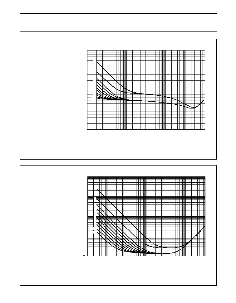
Fig.10 Typical multiplier of ESR as a function of ambient temperature.
Curve 1: 6.3 V; 10 V; 16 V.
Curve 2: 25 V; 40 V; 63 V.
Curve 3: 100 V; 200 V.
ESR
0
= typical at 20
∞
C; 100 Hz.
Case
D
◊
L = 18
◊
30 to 21
◊
38 mm.
MGB243
0
150
50
100
1
10
50
100
Tamb ( C)
o
3
ESR 0
ESR
10
2
10
1
1
2
1
2
3

2002 Jun 07
14
BCcomponents
Product specification
Aluminum electrolytic capacitors
Axial High Temperature
118 AHT
Fig.11 Typical multiplier of ESR as a function of frequency.
Curve 1: 63 V; 100 V (
15
µ
F).
Curve 2: 40 V.
Curve 3: 25 V.
Curve 4: 6.3 V; 10 V; 16 V.
ESR
0
= typical at 20
∞
C; 100 Hz.
Case
D
◊
L = 6.5
◊
18 to 10
◊
25 mm.
0
10
5
MGB244
10
4
10
3
10
2
10
f (Hz)
0.4
0.8
1.2
1.6
2.0
3
1
ESR 0
ESR
4
2
1
2
3
4
Fig.12 Typical multiplier of ESR as a function of frequency.
Curve 1: 200 V.
Curve 2: 100 V.
Curve 3: 40 V; 63 V.
Curve 4: 16 V; 25 V.
Curve 5: 6.3 V; 10 V.
ESR
0
= typical at 20
∞
C; 100 Hz.
Case
D
◊
L = 10
◊
30 to 21
◊
38 mm.
0
10
5
MGB245
10
4
10
3
10
2
10
f (Hz)
0.4
0.8
1.2
1.6
3
2
ESR 0
ESR
5
4
1
1
2
3
4
5
2002 Jun 07
15
BCcomponents
Product specification
Aluminum electrolytic capacitors
Axial High Temperature
118 AHT
Impedance (Z)
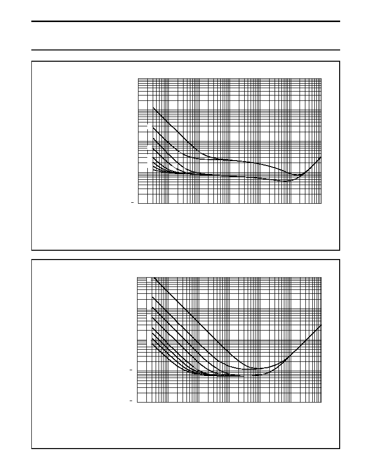
Fig.13 Typical impedance as a function of frequency.
Curve 1: 47
µ
F.
Curve 2: 100
µ
F.
Curve 3: 220
µ
F.
Curve 4: 470
µ
F.
Case
D
◊
L = 8
◊
18 mm.
T
amb
= 20
∞
C.
10
6
MGB246
10
5
10
4
10
3
10
2
10
3
10
2
10
1
10
1
f (Hz)
2
Z
( )
1
3
4
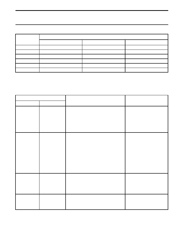
Fig.14 Typical impedance as a function of frequency.
Curve 1: 100
µ
F.
Curve 2: 220
µ
F.
Curve 3: 470
µ
F.
Curve 4: 1000
µ
F.
Case
D
◊
L = 10
◊
25 mm.
T
amb
= 20
∞
C.
10
6
MGB247
10
5
10
4
10
3
10
2
10
3
10
2
10
1
10
1
f (Hz)
1
4
Z
( )
2
3
2002 Jun 07
16
BCcomponents
Product specification
Aluminum electrolytic capacitors
Axial High Temperature
118 AHT
Fig.15 Typical impedance as a function of frequency.
10
6
MGB248
10
5
10
4
10
3
10
2
10
10
7
f (Hz)
10
3
10
2
10
1
10
1
Z
( )
2
3
4
5
6
7
8
9
11
10
1
Curve 1: 22
µ
F, 200 V.
Curve 2: 68
µ
F, 100 V.
Curve 3: 150
µ
F, 63 V.
Curve 4: 220
µ
F, 63 V.
Curve 5: 330
µ
F, 40 V.
Curve 6: 470
µ
F, 40 V.
Curve 7: 680
µ
F, 25 V.
Curve 8: 1000
µ
F, 25 V and 1000
µ
F, 16 V.
Curve 9: 1500
µ
F, 16 V and 1500
µ
F, 10 V.
Curve 10: 2200
µ
F, 10 V and 2200
µ
F, 6.3 V.
Curve 11: 3300
µ
F, 6.3 V.
Case
D
◊
L = 12.5
◊
30 mm.
T
amb
=
-
40
∞
C.
Fig.16 Typical impedance as a function of frequency.
10
6
MGB249
10
5
10
4
10
3
10
2
10
10
7
f (Hz)
10
3
10
2
10
1
10
1
Z
( )
1
2
3
4
5
6
7
8
9
10
11
Curve 1: 22
µ
F, 200 V.
Curve 2: 68
µ
F, 100 V.
Curve 3: 150
µ
F, 63 V.
Curve 4: 220
µ
F, 63 V.
Curve 5: 330
µ
F, 40 V.
Curve 6: 470
µ
F, 40 V.
Curve 7: 680
µ
F, 25 V.
Curve 8: 1000
µ
F, 25 V and 1000
µ
F, 16 V.
Curve 9: 1500
µ
F, 16 V and 1500
µ
F, 10 V.
Curve 10: 2200
µ
F, 10 V and 2200
µ
F, 6.3 V.
Curve 11: 3300
µ
F, 6.3 V.
Case
D
◊
L = 12.5
◊
30 mm.
T
amb
= 20
∞
C.
2002 Jun 07
17
BCcomponents
Product specification
Aluminum electrolytic capacitors
Axial High Temperature
118 AHT
Fig.17 Typical impedance as a function of frequency.
Curve 1: 47
µ
F, 200 V.
Curve 2: 220
µ
F, 100 V.
Curve 3: 470
µ
F, 63 V.
Curve 4: 1000
µ
F, 40 V.
Curve 5: 2200
µ
F, 25 V.
Curve 6: 3300
µ
F, 18 V.
Curve 7: 4700
µ
F, 10 V.
Curve 8: 6800
µ
F, 6.3 V.
Case
D
◊
L = 18
◊
30 mm.
T
amb
=
-
40
∞
C.
10
6
MGB250
10
5
10
4
10
3
10
2
10
10
7
f (Hz)
1
3
8
10
3
10
2
10
1
10
1
Z
( )
2
4
5
6
7
Fig.18 Typical impedance as a function of frequency.
Curve 1: 47
µ
F, 200 V.
Curve 2: 220
µ
F, 100 V.
Curve 3: 470
µ
F, 63 V.
Curve 4: 1000
µ
F, 40 V.
Curve 5: 2200
µ
F, 25 V.
Curve 6: 3300
µ
F, 18 V.
Curve 7: 4700
µ
F, 10 V.
Curve 8: 6800
µ
F, 6.3 V.
Case size
D
◊
L = 18
◊
30 mm.
T
amb
= 20
∞
C.
10
6
MGB251
10
5
10
4
10
3
10
2
10
10
7
f (Hz)
10
2
10
2
10
1
10
1
Z
( )
1
2
3
4
5
6
8
7

2002 Jun 07
18
BCcomponents
Product specification
Aluminum electrolytic capacitors
Axial High Temperature
118 AHT
RIPPLE CURRENT AND USEFUL LIFE
Fig.19 Multiplier of useful life as a function of ambient temperature and ripple current load; see Table 5.
I
A
= actual ripple current at 100 Hz.
I
R
= rated ripple current at 100 Hz, 125
∞
C.
(1) Useful life at 125
∞
C and I
R
applied:
case
D
◊
L = 6.5
◊
18 to 10
◊
25 mm: 4000 hours
case
D
◊
L = 10
◊
30 to 21
◊
38 mm: 8000 hours
.
3.8
3.7
3.6
3.5
3.4
3.3
3.2
3.0
2.8
2.6
2.4
2.2
2.0
1.8
1.6
1.4
1.2
1.0
0.8
0.5
0.0
3.1
40
50
60
70
80
90
100
110
Tamb ( C)
o
120
130
MBC242
3.9
4.0
4.1
4.2
4.3
lifetime multiplier
(1)
I A
R
I
6.0
4.0
2.0
1.5
1.0
3.0
400
100
60
20
30
12
8.0
200
2002 Jun 07
19
BCcomponents
Product specification
Aluminum electrolytic capacitors
Axial High Temperature
118 AHT
Table 5
Multiplier of ripple current (I
R
) as a function of frequency
SPECIFIC TESTS AND REQUIREMENTS
General tests and requirements are specified in data handbook BC01, section "Tests and Requirements".
Table 6
Test procedures and requirements
FREQUENCY
(Hz)
I
R
MULTIPLIER
U
R
= 6.3 to 25 V
U
R
= 40 to 63 V
U
R
= 100 to 200 V
50
0.95
0.9
0.85
100
1.0
1.0
1.0
300
1.07
1.12
1.2
1000
1.12
1.2
1.3
3000
1.15
1.25
1.35
10000
1.2
1.3
1.4
TEST
PROCEDURE
(quick reference)
REQUIREMENTS
NAME OF TEST
REFERENCE
Endurance
IEC 60384-4/
EN130300
subclause 4.13
T
amb
= 125
∞
C; U
R
applied;
case sizes:
6.5
◊
18 to 10
◊
25 mm: 2000 hours;
10
◊
30 to 21
◊
38 mm: 3000 hours
U
R
6.3 V;
C/C: +15/
-
30%
U
R
>
6.3 V;
C/C:
±
15%
tan
1.3
◊
spec. limit
Z
2
◊
spec. limit
I
L5
spec. limit
Useful life
CECC 30301
subclause 1.8.1
T
amb
= 125
∞
C; U
R
and I
R
applied;
case
D
◊
L = 6.5
◊
18 to 10
◊
25 mm:
4000 hours;
case
D
◊
L = 10
◊
30 to 21
◊
38 mm:
8000 hours
U
R
6.3 V;
C/C: +45/
-
50%
U
R
>
6.3 V;
C/C:
±
45%
tan
3
◊
spec. limit
Z
3
◊
spec. limit
I
L5
spec. limit
no short or open circuit
total failure percentage:
1%
(200 V
3%)
Shelf life
(storage at high
temperature)
IEC 60384-4/
EN130300
subclause 4.17
T
amb
= 125
∞
C; no voltage applied;
U
R
= 6.3 to 63 V: 500 hours;
U
R
= 100 and 200 V: 100 hours
after test: U
R
to be applied for 30 minutes,
24 to 48 hours before measurement
C/C, tan
, Z:
for requirements
see `Endurance test' above
I
L5
2
◊
spec. limit
Reverse voltage
IEC 60384-4/
EN130300
subclause 4.15
T
amb
= 125
∞
C:
125 hours at U =
-
1 V
followed by 125 hours at U
R
C/C:
±
20%
tan
spec. limit
I
L5
spec. limit