 | –≠–ª–µ–∫—Ç—Ä–æ–Ω–Ω—ã–π –∫–æ–º–ø–æ–Ω–µ–Ω—Ç: 80-0211-C | –°–∫–∞—á–∞—Ç—å:  PDF PDF  ZIP ZIP |

SC-691
Speech And Music Processor
Data sheet
© 2003 Sensory Inc.
P/N 80-0211-C
1
Features
Advanced, Catalog Speech Processor for High-
Quality Sound, Capable of Unlimited Speech
Duration Using External Memory
Operates up to 12.32 MIPS.
Supports High-Quality Algorithms Such as MX
(1.0 Kbps ≠ 3.5 Kbps at 8 kHz), CX (3.0 Kbps ≠
11.2 kHz at 8 kHz Sampling Rate), ADPCM,
Single Channel FM with CX or MX.
Speed and Pitch Shifting in MX for Various
Voice Effects.
Six Level Digital Gain Control.
4 User Configurable I/O's.
Very Low-Power Operation, Ideal for Hand-Held
Devices.
Low-Voltage Operation, Sustainable by Three
(3) Batteries.
Three Reduced Power Standby Modes, Less
Than 10 µA in Deep-Sleep Mode.
Resistor-Trimmed Oscillator or 32.768 kHz
Crystal Reference Oscillator.
Direct Speaker Drive, 32 (PDM).
Interrupt Driven, 4 or 8-Bit Parallel Data
Transfer Protocol.
Available in Die Form or 64-Pin LQFP Package
Description
The SC-691 is a standard slave synthesizer
from Sensory, Inc. that accepts compressed
speech data from other microprocessors or
microcontrollers and converts it to speech.
This allows the SC-691 to be used with a master
microprocessor/microcontroller in various
speech-related products such as security
systems, learning aids, games, and toys. High
quality, low bit-rate coders, easy interface with
the master microcontroller, digital gain control,
low power sleep mode, and low voltage
operation makes this device ideal for products
requiring long duration speech, less
development cycle times, and peripheral device
control through the slave device.
This device supports several speech synthesis algorithms that permit tradeoffs to meet the price performance
requirements of various markets.
The SC-691 implements a unique feature of playing a single channel FM music along with CX or MX speech
data concurrently. This feature allows the user to speak a certain phrase in MX or CX with single channel music
in the background.
The SC-691 is optimized to support a 4-bit wide data transfer protocol. The device has two status bits and three
control bits that control the communication protocol between the master and the slave.
The SC-691 also has 1 bit (command/data) which differentiates between a command and speech data feeding
into the slave. In 4-bit mode, various commands are sent to the slave during speech to perform various tasks.
The SC-691 also supports the 8-bit wide data transfer but the support for commands is disabled during
speaking-a-phrase. When speaking-a-phrase in 8-bit mode is complete, the SC-691 switches back to the 4-bit
mode to receive the next command. Switching between 4 bit mode and 8 bit mode is permitted between speech
data files.
SC-691 Block Diagram
16-Bit
Microprocessor
640-words
RAM
TIMER 1
TIMER 2
PLLM
10-Bit
DAC
SLAVE LOGIC
COMPARATOR

SC-691
Data sheet
2
P/N 80-0211-C
© 2003 Sensory Inc.
Functional Block Diagram

Data Sheet
SC-691
© 2003 Sensory Inc.
P/N 80-0211-C
3
Pin/Pad Assignments
SC-691
(top view of the die)
36
1
16
35
17
34
SC-691
(64-lead LQFP)
VSS
DACP
PD5
PD6
PD7
DATA0
DATA1
48
47
42
41
40
39
38
DATA2
DATA3
DATA4
37
36
35
VDD
46
DACM
VDD
PD4
45
44
43
DATA5
34
DATA6
33
17
18
19
20
21
22
23
24
32
NC
NC
NC
NC
NC
NC
NC
NC
DA
T
A
7
25
26
27
28
29
30
31
NC
NC
NC
NC
NC
NC
VD
D
64
63
62
54
VSS
NC
NC
NC
61
60
59
58
57
56
55
NC
NC
NC
NC
NC
NC
NC
53
52
51
50
49
NC
NC
NC
NC
VSS
VDD
VDD
R/W_
STROBE_
OUTRDY_
INRDY_
TEST
SCANOUT
SYNC
SCANCLK
SCANIN
RESET_
1
2
3
4
5
6
7
8
9
10
11
12
PLL
OSCIN
OSCOUT
VSS
13
14
15
16
NAME
PIN NO. PAD NO. I/O DESCRIPTION
DATA0≠DATA3
39
36 25
22 I/O Data bits 0 through 3 (in 4-bit or 8-bit mode)
DATA4 or
DATA/COMMAND
35 21
I/O
Data bit 4 (in 8-bit mode)
NOTE: Pin 8 is DATA4 in 8-bit mode, or DATA/COMMAND in 4-bit mode.
DATA5≠DATA7
34
32 20
18 I/O Data bits 5 through 7 (8-bit mode only)
INRDY_ 6
6
O
An output signal from the slave to the microcontroller. A low signal indicates that
the SC-691 is ready to accept data or command. A high signal indicates that the
SC-691 is busy and the microcontroller must not write any data or command to it
OUTRDY_ 5
5
O
An output signal from the slave to the microcontroller. A low signal indicates that
the SC-691 is ready to send data or command to the microcontroller.
PD4≠PD7
43
40 29
26 I/O General-purpose I/O bus
R/W_ 3
3
I
An input signal to the slave from the microcontroller. Read/write select signal which
is set high for read operations or set low for write operations by the microcontroller.
STROBE_ 4
4
I
An input signal to the slave from the microcontroller. STROBE_ sequences read or
write operations in conjunction with the R/W_ signal. This signal is pulsed high-low-
high for read or write operations sequencing.
Reference Oscillator Signals
OSCOUT
15
15
O Output of resistor/crystal oscillator
OSCIN
14
14
I Input to resistor/crystal oscillator
PLL
13
13
O Output of phase-lock-loop filter
Scan Port Control Signals
SCANIN
11
11
I Scan port data input
SCANOUT
8
8
O Scan port data output
SCANCLK
10
10
I Scan port clock
SYNC
9
9
I Scan port synchronization
TEST
7
7
I
Test
modes
Digital-to-Analog Sound Output
DACP
47
33
O Digital-to-analog plus output (+)
DACM
45
31
O Digital-to-analog minus output(≠)
Initialization
RESET_ 12
12
I
Device
initialization
Power Signals
V
DD
1, 2, 31,
44, 46
1, 2, 17,
30, 32
- Processor power, 5 V nominal supply voltage
V
SS
16, 48,
49
, 64
16, 34
,
35, 36
- Ground
pin
All pins must be N.C.
Marked pins are
V
DD
and
V
SS
connections which service the DAC circuitry. These pins tend to sustain a higher current draw. A dedicated
decoupling capacitor across these pins is therefore required.
SC-691
Data sheet
4
P/N 80-0211-C
© 2003 Sensory Inc.
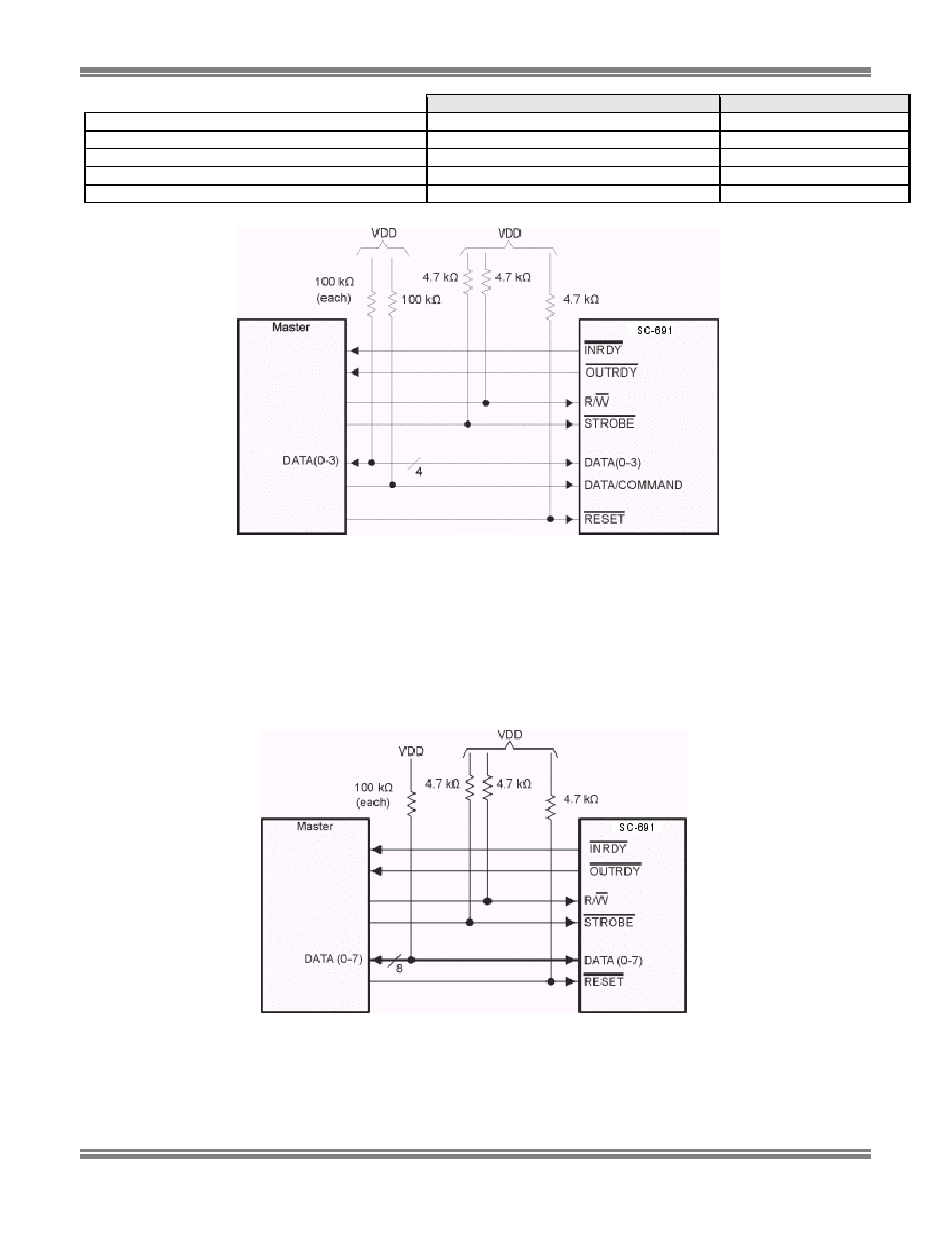
SC-691 (4-bit mode)
SC-691 (8-bit mode)
Number of data lines
4
8
Number of control lines
3 (STROBE_, R/W_, data/command)
2 (STROBE_, R/W_)
Number of status lines
2 (INRDY_, OUTRDY_)
2 (INRDY_, OUTRDY_)
Number of general-purpose I/O lines
4
4
Support for commands (while speaking)
Yes
No
Figure 1: Interfacing Diagram 4-Bit Mode
Note:
STROBE_
Active low STROBE_ signal from microcontroller
R/W_
Read/write signal from microcontroller
RESET_
Active low RESET_ signal from microcontroller
DATA0≠
DATA3 Data bits 0 through 3
PD4≠PD7
General-purpose I/O bus
DACP
Output to speaker/amplifier
DACM
Output to speaker/amplifier
DATA/COMMAND
This bit determines if the data sent by the microcontroller is data or command.
Figure 2: Interfacing Diagram 8-Bit Mode
Note:
STROBE_
Active low STROBE_ signal from microcontroller
R/W_
Read/write signal from microcontroller
RESET_
Active low RESET_ signal from microcontroller.
INRDY_
Active low indicates that the SC-691 is ready to accept data.
OUTRDY_
Active low indicates that the SC-691 is ready to send data.

Data Sheet
SC-691
© 2003 Sensory Inc.
P/N 80-0211-C
5
DATA0≠DATA7
Data bits 0 through 7
PD4≠PD7
General-purpose I/O bus
DACP
Output to speaker/amplifier
DACM
Output to speaker/amplifier