
Rhopoint Components Ltd
Fax: +44 (0) 1883 712938 Phone: +44 (0) 1883 717988 web: www.rhopointcomponents.com e-mail: sales@rhopointcomponents.com
9200-9300 Series/Surface Mount Reed Relays
S
S
S
S
S
URF
URF
URF
URF
URFA
A
A
A
ACE
CE
CE
CE
CE
M
M
M
M
M
OUNT
OUNT
OUNT
OUNT
OUNT
R
R
R
R
R
EED
EED
EED
EED
EED
R
R
R
R
R
ELA
ELA
ELA
ELA
ELAYS
YS
YS
YS
YS
Ideally suited to the needs of Automated Test Equipment, Instrumentation
and Telecommunications requirements, Coto's 9200, and 9300 Series
specification tables allow you to select the appropriate relay for your
particular application. If your requirements differ, please consult your
local representative or Coto's Factory to discuss a custom design.
S
S
S
S
S
ERIES
ERIES
ERIES
ERIES
ERIES
F
F
F
F
F
EA
EA
EA
EA
EATURES
TURES
TURES
TURES
TURES
u
High Insulation Resistance - 10
12
minimum (10
13
Typical).
u
High reliability, hermetically sealed contacts for long life.
u
Molded thermoset body on integral lead frame design.
u
High speed switching compared to electromechanical relays.
9200 Ser
9200 Ser
9200 Ser
9200 Ser
9200 Series
ies
ies
ies
ies
u
Low profile - 0.19" height. Meets high board density requirements.
u
50
Coaxial Shield for RF and Fast Rise Time Pulse switching.
9300 Ser
9300 Ser
9300 Ser
9300 Ser
9300 Series
ies
ies
ies
ies
u
Load switching (15 Watts) and high dielectric strength (500 VDC)
between contacts.
Dimensions in Inches (Millimeters)
Model 9200
Model 9300
Gull Wing
Gull Wing
Axial
J-Lead
J-Lead
Radial
Axial
Rhopoint Components Ltd
Fax: +44 (0) 1883 712938 Phone: +44 (0) 1883 717988 web: www.rhopointcomponents.com e-mail: sales@rhopointcomponents.com
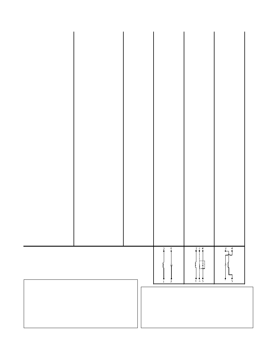
Model Number
9201
9202
9301
Parameters
Test Conditions
Units
1 Form A
1 Form A
COIL SPECS.
Nom. Coil Voltage
VDC
5 12
5 12
5 12
Max. Coil Voltage
VDC
6.5 15.0
6.5 15.0
6.5 15.0
Coil Resistance
+/- 10%, 25∞ C
250 650
150 650
350 1000
Operate Voltage
Must Operate by
VDC - Max.
3.75 9.0
3.75 9.0
3.75 9.0
Release Voltage
Must Release by
VDC - Min.
0.4 1.0
0.4 1.0
0.4 1.0
CONTACT RATINGS
Switching Voltage
Max DC/Peak AC Resist.
Volts
200
200
200
Switching Current
Max DC/Peak AC Resist.
Amps
0.5
0.5
0.5
Carry Current
Max DC/Peak AC Resist.
Amps
1.5
1.5
1.5
Contact Rating
Max DC/Peak AC Resist.
Watts
10
10
15
Life Expectancy-Typical
1
Signal Level 1.0V,10mA
x 10
6
Ops.
1000
1000
250
Static Contact
Resistance (max. init.)
50mV, 10mA
0.150
0.150
0.150
Dynamic Contact
Resistance (max. init.)
0.5V, 50mA
at 100 Hz, 1.5 msec
0.200
0.200
0.200
RELAY SPECIFICATIONS
Insulation Resistance
(minimum)
Between all Isolated Pins
at 100V, 25∞C, 40% RH
x
10
12
x
10
12
x
10
12
Capacitance - Typical
Across Open Contacts
No Shield
Shield Floating
Shield Guarding
pF
pF
pF
0.7
-
-
-
0.8
0.1
0.7
-
-
Open Contact to Coil
No Shield
Shield Floating
Shield Guarding
pF
pF
pF
1.4
-
-
-
1.4
0.2
1.4
-
-
Contact to Shield
Contacts Open,
Shield Floating
pF
-
1.4
-
Dielectric Strength
(minimum)
Between Contacts
Contacts to Shield
Contacts/Shield to Coil
VDC/peak AC
VDC/peak AC
VDC/peak AC
300
-
1500
300
1500
1500
x
500
3
-
1500
Operate Time - including
bounce - Typical
At Nominal Coil Voltage,
30 Hz Square Wave
msec.
0.40
0.40
0.40
Release Time - Typical
Zener-Diode Suppression
4
msec.
0.10
0.10
0.10
1 Form A
50
Coaxial
9200-9300 Series/Surface Mount Reed Relays
Environmental Ratings
Storage Temp: -35∞C to +100∞C;
Operating Temp: -20∞C to +85∞C
The operate and release voltage and the coil resistance
are specified at 25∞C. These values vary by approximately
0.4%/∞C as the ambient temperature varies.
Vibration: 20 G's to 2000 Hz; Shock: 50 G's
Notes:
1
Consult factory for life expectancy at other switching loads.
2
Surface mount component processing temperature:
430∞F(221∞C) max for 1 minute dwell time. Temperature
measured on leads where lead exits molded package.
3
Higher dielectric strength available, consult factory.
4
Consists of 20V Zener-diode and 1N1002 diode in series,
connected in parallel with coil.
Top View:
Dot stamped on top of relay refers to pin #1 location