 | –≠–ª–µ–∫—Ç—Ä–æ–Ω–Ω—ã–π –∫–æ–º–ø–æ–Ω–µ–Ω—Ç: ELM327 | –°–∫–∞—á–∞—Ç—å:  PDF PDF  ZIP ZIP |
ELM327
Elm Electronics ≠ Circuits for the Hobbyist
www.elmelectronics.com
OBD to RS232 Interpreter
Almost all new automobiles produced today are
required, by law, to provide an interface from which
test equipment can obtain diagnostic information.
The data transfer on these interfaces follow several
standards, none of which are directly compatible
with PCs or PDAs. The ELM327 is designed to act
as a bridge between these On-Board Diagnostics
(OBD) ports and standard PC RS232 ports.
The ELM327 builds on improved versions of our
proven ELM320, ELM322, and ELM323 interfaces
by adding four CAN protocols to them. The result is
an IC that can automatically sense and convert the
nine most common protocols in use today. There are
a number of other improvements as well - a high
speed RS232 option with data buffering, battery
voltage monitoring, and the ability to remember the
last used protocol, to name only a few.
The following is only a "Quick Summary" of the
ELM327. For Example Applications, and a more
detailed discussion of the many features, download
the full datasheet.
∑ Supports 9 OBDII protocols
∑ Automatically searches for a protocol
∑ Fully configurable with AT commands
∑ High and Medium speed RS232
∑ Voltage input for battery monitoring
∑ Low power CMOS design
∑ Diagnostic trouble code readers
∑ Automotive scan tools
∑ Teaching aids
Description
Applications
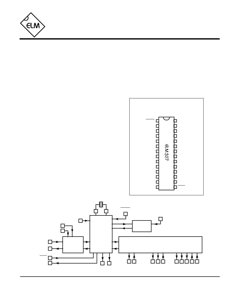
Block Diagram
Features
ELM327QSA
Connection Diagram
PDIP and SOIC
(top view)
OBD Tx LED
OBD Rx LED
RS232 Tx LED
RS232 Rx LED
CAN Rx
CAN Tx
ISO L
ISO K
V
DD
RS232 Rx
RS232 Tx
Busy
RTS
MCLR
Memory
Baud Rate
LFmode
J1850 Volts
XT1
XT2
V
SS
ISO In
PWM In
J1850 Bus+
VPW In
J1850 Bus-
Vmeasure
V
SS
1 of 5
9
10
XT1
XT2
18
17
Command
and
Protocol
Interpreter
6
RS232Tx
RS232Rx
LFmode
4.00 MHz
RS232
Interface
2
7
12
24
23
22
21
ISO 15765-4
CAN
ISO 9141-2
ISO 14230-4
SAE J1850
PWM & VPW
11
13
4
3
14
A/D
Converter
15
16
Baud Rate
25
28
...
5
Memory
status LEDs
OBD interfaces
1
Busy
MCLR
Vmeasure
RTS

ELM327
Elm Electronics ≠ Circuits for the Hobbyist
www.elmelectronics.com
Pin Descriptions
2 of 5
All rights reserved. Copyright 2005 Elm Electronics Inc.
Every effort is made to verify the accuracy of information provided in this document, but no representation or warranty can be
given and no liability assumed by Elm Electronics with respect to the accuracy and/or use of any products or information
described in this document. Elm Electronics will not be responsible for any patent infringements arising from the use of these
products or information, and does not authorize or warrant the use of any Elm Electronics product in life support devices and/or
systems. Elm Electronics reserves the right to make changes to the device(s) described in this document in order to improve
reliability, function, or design.
MCLR (pin 1)
A logic low applied to this input will reset the IC. If
unused, this pin should be connected to a logic high
(V
DD
) level.
Vmeasure (pin 2)
This analog input is used to measure a 0 to 5V
signal that is applied to it. Care must be taken to
prevent the voltage from going outside of the supply
levels of the ELM327, or damage may occur.
J1850 Volts (pin 3)
This output can be used to control a voltage supply
for the J1850 Bus + output. The pin will output a
logic high level when a nominal 8V is required (for
J1850 VPW), and will output a low level when 5V is
needed (as for J1850 PWM applications). If this
switching capability is not required for your
application, this output can be left open-circuited.
J1850 Bus+ (pin 4)
This active high output is used drive the J1850 Bus +
Line to an active level. Note that this signal does not
have to be used for the Bus - Line (as was the case
for the ELM320), since a separate J1850 Bus - drive
output is provided on pin 14.
Memory (pin 5)
This input controls the default state of the memory
option. If this pin is at a high level during power-up or
reset, the memory function will is enabled by default.
If it is at a low level, then the default will be to have it
disabled. Memory can always be controlled with the
AT M1 and AT M0 commands at other times.
Baud Rate (pin 6)
This input controls the baud rate of the RS232
interface. If it is at a high level during power-up or
reset, the baud rate will be set to 38400. If at a low
level, the baud rate will be 9600.
LFmode (pin 7)
This input is used to select the default linefeed mode
to be used after a power-up or system reset. If it is at
a high level, then by default messages sent by the
ELM327 will be terminated with both a carriage
return and a linefeed character. If it is at a low level,
lines will be terminated by a carriage return only.
This behaviour can always be modified by issuing an
AT L1 or AT L0 command (see the section on AT
Commands).
V
SS
(pins 8 and 19)
Circuit common must be connected to these pins.
XT1 (pin 9) and XT2 (pin 10)
A 4.000 MHz oscillator crystal is connected between
these two pins. Loading capacitors as required by
the crystal (typically 27pF each) will also normally be
connected between each of these pins and circuit
common (Vss).
VPW In (pin 11)
This is the active high input for the J1850 VPW data
signal. When at rest (bus recessive) this pin should
be at a low logic level. This input has Schmitt trigger
waveshaping, so no special amplification is required.
ISO In (pin 12)
This is the active low input for the ISO 9141 and
ISO 14230 data signal. It is derived from the K Line,
and should be at a high logic level when at rest (bus
recessive). No special amplification is required, as
this input has Schmitt trigger waveshaping.
PWM In (pin 13)
This is the active low input for the J1850 PWM data
signal. It should normally be at a high level when at
rest (ie. bus recessive). This input has Schmitt
trigger waveshaping, so no special amplification is
required.
ELM327QSA

Elm Electronics ≠ Circuits for the Hobbyist
www.elmelectronics.com
ELM327
3 of 5
ELM327QSA
Ordering Information
These integrated circuits are 28 pin devices, available in either the 300 mil plastic DIP format or in the 300 mil SOIC
surface mount type of package. To order, add the appropriate suffix to the part number:
300 mil 28 pin Plastic DIP..............................ELM327P
300 mil 28 pin SOIC....................................ELM327SM
J1850 Bus- (pin 14)
This active high output is used to drive the J1850
Bus - Line to an active (dominant) level for J1850
PWM applications. If unused, the output can be left
open-circuited.
RTS (pin 15)
This active low "Request To Send" input can be
used to interrupt processing in order to send a new
command. Normally high, the line is brought low for
attention, and should remain so until the Busy line
(pin 16) indicates that the ELM327 is no longer busy.
This input has Schmitt trigger waveshaping.
Busy (pin 16)
This active high output shows the current state of the
ELM327. If it is at a low level, the processor is ready
to receive ASCII commands and characters, but if it
is at a high level, commands are being processed.
RS232Tx (pin 17)
This is the RS232 data transmit output. The signal
level is compatible with most interface ICs (output is
normally high), and there is sufficient current drive to
allow interfacing using only a PNP transistor, if
desired.
RS232Rx (pin 18)
This is the RS232 receive data input. The signal
level is compatible with most interface ICs (the level
is normally high), but can be used with other
interfaces as well, since the input has Schmitt trigger
waveshaping.
V
DD
(pin 20)
This pin is the positive supply pin, and should always
be the most positive point in the circuit. Internal
circuitry connected to this pin is used to provide
power on reset of the microprocessor, so an external
reset signal is not required. Refer to the Electrical
Characteristics section for further information.
ISO K (pin 21) and ISO L (pin 22)
These are the active high output signals which are
used to drive the ISO 9141 and ISO 14230 buses to
an active (dominant) level. Many new vehicles do not
require the L Line - if yours does not, you can simply
leave pin 22 open-circuited.
CAN Tx (pin 23) and CAN Rx (pin 24)
These are the two CAN interface signals that must
be connected to a CAN transeiver IC for proper
operation. If you are connecting to an existing CAN
system, the integrity of that sysem might be
jeopardized if a proper interface is not used. See the
Example Applications section for more information.
RS232 Rx LED (pin 25), RS232 Tx LED (pin 26),
OBD Rx LED (pin 27) and OBD Tx LED (pin 28)
These four output pins are normally high, and are
driven to low levels when the ELM327 is transmitting
or receiving data. Current capability is suitable for
directly driving most LEDs through current limiting
resistors, or interfacing to other logic for status
reporting. If unused, these pins should be left open-
circuited.
Pin Descriptions (continued)

Electrical Characteristics
Absolute Maximum Ratings
Storage Temperature....................... -65∞C to +150∞C
Ambient Temperature with
Power Applied....................................-40∞C to +85∞C
Voltage on V
DD
with respect to V
SS
............ 0 to +7.5V
Voltage on any other pin with
respect to V
SS
........................... -0.3V to (V
DD
+ 0.3V)
Note:
Stresses beyond those listed here will likely damage
the device. These values are given as a design
guideline only. The ability to operate to these levels
is neither inferred nor recommended.
Notes:
1. This integrated circuit is produced with a Microchip Technology Inc.'s PIC18F248 or PIC18F2480 as the
core embedded microcontroller. For further device specifications, and possibly clarification of those given,
please refer to the appropriate Microchip documentation (available at http://www.microchip.com/).
2. This spec must be met in order to ensure that a correct power on reset occurs. It is quite easily achieved
using most common types of supplies, but may be violated if one uses a slowly varying supply voltage, as
may be obtained through direct connection to solar cells, or some charge pump circuits.
3. Device only. Does not include any load currents.
4. Pins 1, 11, 12, 13, 15 and 18 have internal Schmitt trigger waveshaping circuitry
5. The typical width of the Busy output pulse while the ELM327 interprets the command, measures the voltage,
scales it and transmits the result of a mid-range measurement at 38400 baud.
4 of 5
ELM327
ELM327QSA
Elm Electronics ≠ Circuits for the Hobbyist
www.elmelectronics.com
All values are for operation at 25∞C and a 5V supply, unless otherwise noted. For further information, refer to note 1 below.
Characteristic
Minimum
Typical
Maximum
Conditions
Units
Supply voltage, V
DD
4.5
5.0
5.5
V
V
DD
rate of rise
0.05
V/ms
Average supply current, I
DD
9
mA
Input threshold voltage
1.0
1.3
V
Output low voltage
Output high voltage
current (sink) = 10 mA
current (source) = 10 mA
see note 2
see note 5
see note 3
Schmitt trigger
input thresholds
Brown-out reset voltage
4.07
4.2
4.59
V
rising
falling
A/D conversion time
7
msec
all except Schmitt inputs
V
V
0.3
4.6
V
V
3.0
1.4
see note 4

5 of 5
ELM327
ELM327QSA
Elm Electronics ≠ Circuits for the Hobbyist
www.elmelectronics.com
AT Command Summary
General Commands
D
set all to Defaults
E0
Echo Off
E1
Echo On
I
print the ID
L0
Linefeeds Off (default set by pin 7)
L1
Linefeeds On
WS
Warm Start (quick software restart)
Z
reset all
OBD Commands
AL
Allow Long (>7 byte) messages
BD
perform a Buffer Dump
BI
Bypass the Initialization sequence
DP
Describe the current Protocol
DPN
Describe the Protocol by Number
H0
Headers Off (default)
H1
Headers On
M0
Memory Off (default set by pin 5)
M1
Memory On
MA
Monitor All
MR hh
Monitor for Receiver = hh
MT hh
Monitor for Transmitter = hh
NL
Normal Length (7 byte) messages
PC
Protocol Close
R0
Responses Off
R1
Responses On
SH yzz
Set Header
SH xx yy zz Set Header
SP h
Set Protocol to h and save it
SP Ah
Set Protocol to Auto, h and save it
ST hh
Set Timeout to hh x 4 msec
TP h
Try Protocol h
TP Ah
Try Protocol h with Auto search
CAN Specific Commands
CAF1
CAN Automatic Formatting On
CAF0
CAN Automatic Formatting Off
CF hhh
set the ID Filter to hhh
CF hh hh hh hh
set the ID Filter to hhhhhhhh
CFC1
CAN Flow Control On
CFC0
CAN Flow Control Off
CM hhh set the ID Mask to hhh
CM hh hh hh hh
set the ID Mask to hhhhhhhh
CP hh
set CAN Priority (only for 29 bit)
CS
show the CAN Status
ISO Specific Commands
IB 10
set the ISO Baud rate to 10400
IB 96
set the ISO Baud rate to 9600
SW hh
Set Wakeup interval to hh x 20 msec
WM xx yy zz aa
set the Wakeup Message
WM xx yy zz aa bb
"
"
WM xx yy zz aa bb cc
"
"
Misc. Commands
CV dddd Calibrate the Voltage to dd.dd volts
RV
Read the Voltage