| –≠–ª–µ–∫—Ç—Ä–æ–Ω–Ω—ã–π –∫–æ–º–ø–æ–Ω–µ–Ω—Ç: LD7550IL | –°–∫–∞—á–∞—Ç—å:  PDF PDF  ZIP ZIP |
LD7550
3
Leadtrend Technology Corporation
LD7550-DS-00 August 2004
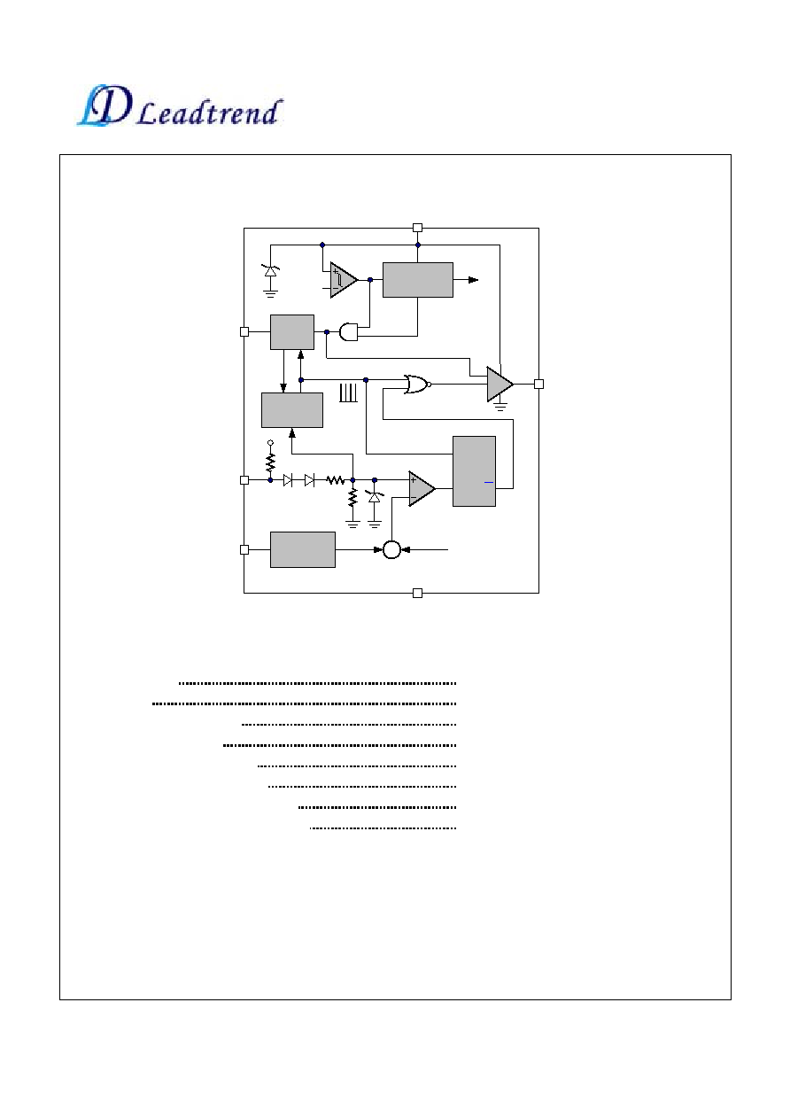
Block Diagram
OSC
COMP
CS
OUT
internal bias
& Vref
VCC
GND
PWM
Comparator
RT
16.0V/
11.4V
UVLO
Green-Mode
Oscillator
Leading
Edge
Blanking
2R
R
40V
R
S
Q
Vref OK
EN
EN
+
+
Ramp from
Oscillator
Absolute Maximum Ratings
Supply Voltage VCC
36V
COMP, RT, CS
-0.3
~7V
Operating Junction Temperature
150
∞
C
Storage Temperature Range
-65
∞
C to 150
∞
C
Package thermal resistance (DIP-8)
100
∞
C/W
Package thermal resistance (SOT-26)
250
∞
C/W
Lead temperature (DIP-8, Soldering, 10sec)
260
∞
C
Lead temperature (SOT-26, Soldering, 10sec)
260
∞
C
Caution:
Stresses beyond the ratings specified in "Absolute Maximum Ratings" may cause permanent damage to the device. This is a stress only
rating and operation of the device at these or any other conditions above those indicated in the operational sections of this specification is not
limited.

LD7550
4
Leadtrend Technology Corporation
LD7550-DS-00 August 2004
Electrical Characteristics
(T
A
= +25
o
C unless otherwise stated, V
CC
=15.0V)
PARAMETER CONDITIONS
MIN
TYP
MAX
UNITS
Supply Voltage (Vcc Pin)
Startup Current
5
25
µ
A
V
COMP
=0V
3
4
mA
V
COMP
=3V
2
mA
Operating Current
V
COMP
=open
0.7
mA
UVLO (off)
10.4
11.4
12.4
V
UVLO (on)
14.8
16.0
17.5
V
Voltage Feedback (Comp Pin)
Short Circuit Current
V
COMP
=0V
2.2
3.0
mA
Open Loop Voltage
COMP pin open
5.0
V
Green Mode Threshold VCOMP
2.35
V
Current Sensing (CS Pin)
Maximum Input Voltage
0.80
0.85
0.90
V
Leading Edge Blanking Time
250
nS
Input impedance
50
K
Delay to Output
300
nS
Oscillator (RT pin)
Frequency RT=100K
61.5
66.5
71.5
KHz
Green Mode Frequency
Fs=66.5KHz
20
KHz
Temp. Stability
(-30
∞
C
~85
∞
C)
5
%
Voltage Stability
(VCC=12V-30V)
2
%
Gate Drive Output (OUT Pin)
Output Low Level
VCC=15V, Io=20mA
1
V
Output High Level
VCC=15V, Io=20mA
8
V
Rising Time
Load Capacitance=1000pF
50
200
nS
Falling Time
Load Capacitance=1000pF
30
125
nS
LD7550
5
Leadtrend Technology Corporation
LD7550-DS-00 August 2004
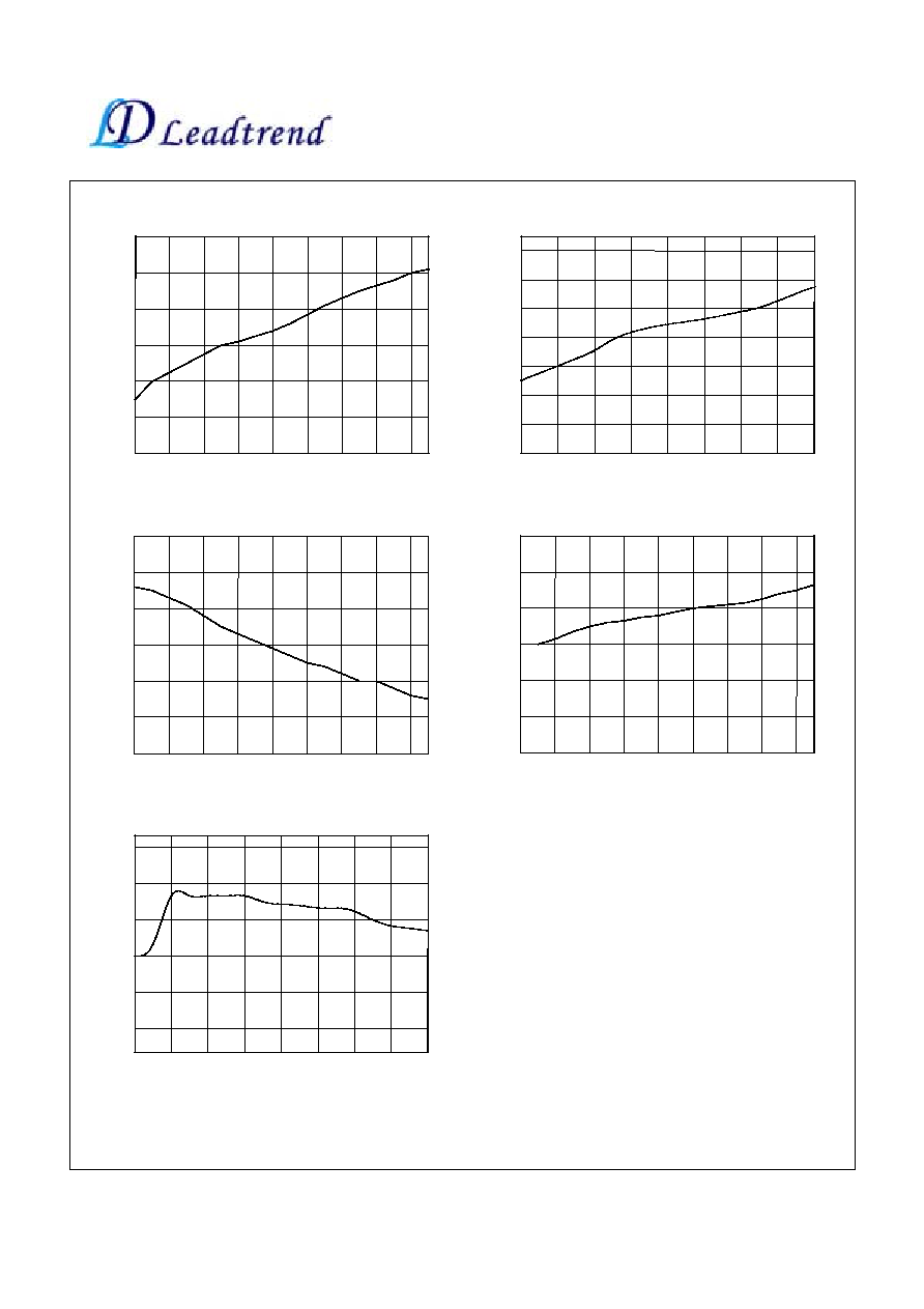
Typical Performance Characteristics
-40
-20
0
20
40
60
80
100
120
11.0
11.2
11.4
11.6
11.8
12.0
12.2
UVL
O
(
O
f
f
)
(V
)
Temperature (
∞
C)
Fig. 1 UVLO (Off) vs. Temperature
U
V
LO (O
n)
(
V
)
Fig. 2 UVLO (On) vs. Temperature
-40
-20
0
20
40
60
80
100
120
14.0
14.4
14.8
15.2
15.6
16.0
16.4
16.8
17.0
Temperature (
∞
C)
F
r
eq
uenc
y
(
K
H
z
)
Temperature (
∞
C)
Fig. 3 Frequency vs. Temperature
-40
-20
0
20
40
60
80
100
120
66.0
67.0
68.0
69.0
70.0
71.0
72.0
F
r
eq
uenc
y
(
K
H
z
)
Fig. 4 Green-Mode Frequency vs. Temperature
Temperature (
∞
C)
-40
-20
0
20
40
60
80
100
120
17.0
17.2
17.4
17.6
17.8
18.0
18.2
Ma
x. Du
ty-
C
yc
le
(
%
)
Temperature (
∞
C)
Fig. 5 Duty-Cycle (max.) vs. Temperature
-40
-20
0
20
40
60
80
100
120
74.4
74.7
75.0
75.3
75.6
75.9