
DATA SHEET
CHIP RESISTORS ARRAY
TC164 (8Pin/4R)
5%
Product Specification ≠ Mar. 24, 2004 V.4
Supersedes Date of Feb. 10,
2004
www.yageo.com
Mar. 24, 2004 V.4
Chip Resistor Surface Mount
2
7
SERIES
TC
164
TYPE TC164
B (mm)
0.3±0.15
H (mm)
0.5±0.15
P (mm)
0.8±0.05
L (mm)
3.2±0.20
T (mm)
0.6±0.1
W
1
(mm)
0.3±0.15
W
2
(mm)
1.6±0.15
Table 1
YNSC021
H
a
a
P
L
B
T
W
1
W
2
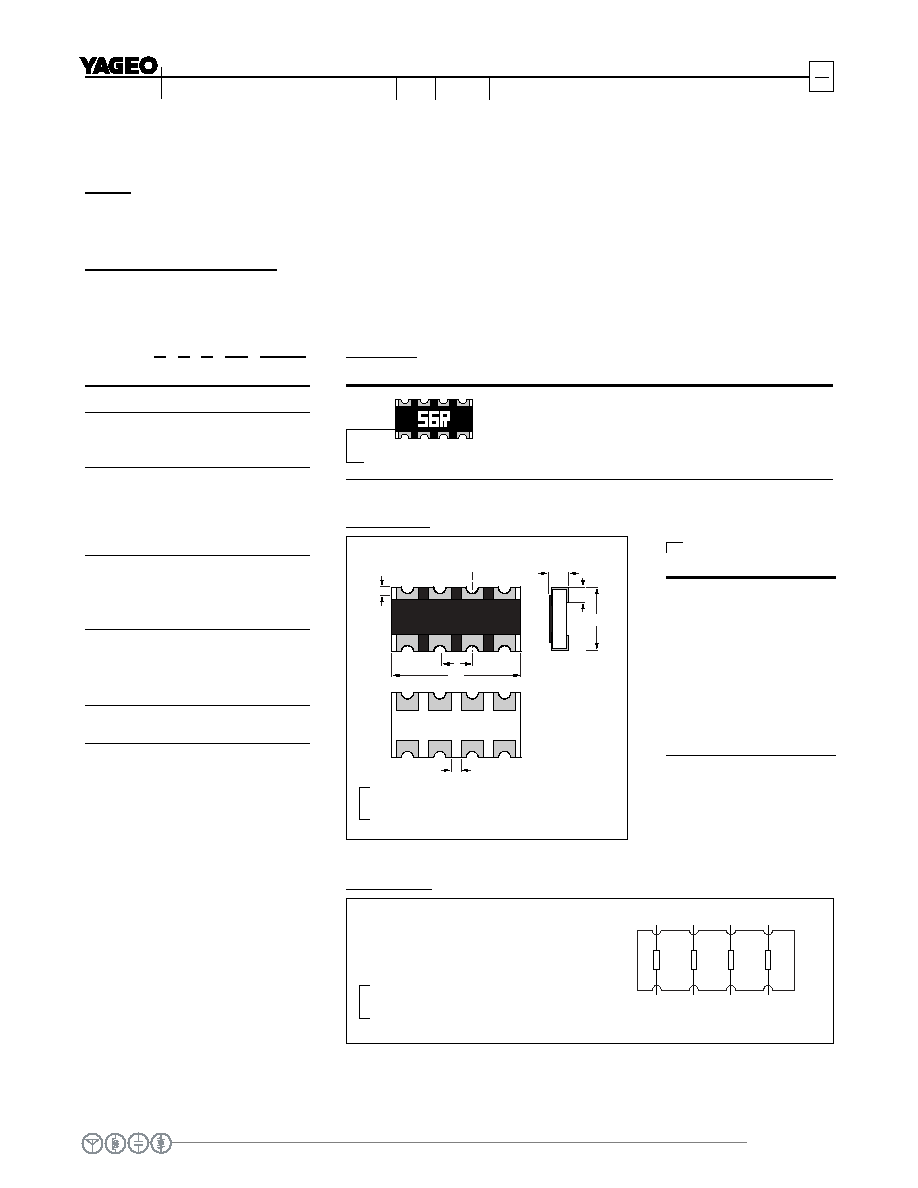
Fig. 2 TC164 series chip resistors construction
DIMENSION
SCHEMATIC
R1
R2
R3
R4
YNSC022
1
2
8
7
3
6
4
5
Fig. 3 Equivalent circuit diagram
For dimension see Fig. 2 and Table 1
R1=R2=R3=R4
TC164
First two digits for significant figure and
3rd digit for number of zeros
Letter R: decimal place
MARKING
Fig. 1 5% Marking, Value=56
YNSC020
TC164 ≠ X X X XX XXXX
(1) (2) (3) (4) (5)
(1) TOLERANCE
J = ±5%
(2) PACKAGING TYPE
R = Paper taping reel
(3) TEMPERATURE
CHARACTERISTIC OF
RESISTANCE
G = ±200ppm/∞C
≠ = Base on spec
(4) SPECIAL TYPE
07 = 7 inch dia. Reel
13 = 13 inch dia. Reel
(5) RESISTANCE VALUE:
56R, 560R, 5K6, 56K, 1M.
SCOPE
This specification describes TC164 series chip resistors made by thick film process.
ORDERING INFORMATION
Part number is identified by the series, size, tolerance, packing style, temperature coefficient, special type and
resistance value.
Concave termination

www.yageo.com
Mar. 24, 2004 V.4
Chip Resistor Surface Mount
3
7
SERIES
TC
164
CHARACTERISTICS
TC164 1/16W
Operating Temperature Range
≠55∞C to +155∞C
Maximum Working Voltage
50V
Maximum Overload Voltage
100V
Dielectric Withstanding Voltage
100V
Number of Resistors
4
Resistance Range
10 to 1M
Zero Ohm Jumper <0.05
Temperature Coefficient
±200ppm/∞C
Rated Current 1.0A
Jumper Criteria
Maximum Current
2.0A
ELECTRICAL CHARACTERISTICS
POWER RATING
R
R
A
A
T
T
E
E
D
D
P
P
O
O
W
W
E
E
R
R
A
A
T
T
7
7
0
0
∞
∞
C
C
,
,
T
T
C
C
1
1
6
6
4
4
=
=
1
1
/
/
1
1
6
6
W
W
F
F
O
O
R
R
E
E
L
L
E
E
M
M
E
E
N
N
T
T
R
R
A
A
T
T
E
E
D
D
V
V
O
O
L
L
T
T
A
A
G
G
E
E
:
:
The DC or AC (rms) continuous
working voltage corresponding to
the rated power is determined by
the following formula:
V=(P X R)
Where
V=Continuous rated DC
or AC (rms) working voltage (V)
P=Rated power (W)
R=Resistance value (X)
Table 2
MRA632
70
100
-55
50
Tamb (
∞
C)
(%Prated)
0
0
50
100
155
Pmax
Fig. 4 Maximum dissipation (P
max
) in
percentage of rated power as
a function of the operating
ambient temperature (T
amb
)

www.yageo.com
Mar. 24, 2004 V.4
Chip Resistor Surface Mount
4
7
SERIES
TC
164
CCB325
empty compartments
with cover tape
(min. 240 mm)
cover tape only
leader
400 mm
trailer (max. 260 mm)
trailer end
leader end
Fig. 7 Leader and trailer tape dimension
PACKING METHOD
L
L
E
E
A
A
D
D
E
E
R
R
/
/
T
T
R
R
A
A
I
I
L
L
E
E
R
R
T
T
A
A
P
P
E
E
S
S
P
P
E
E
C
C
I
I
F
F
I
I
C
C
A
A
T
T
I
I
O
O
N
N
PACKING STYLE
REEL DIMENSION
TC164
Paper Taping Reel (R)
7" (178 mm)
5,000
13" (330 mm)
20,000
gewidth
C
D
B
A
W
T
MSA284_b
DIMENSION TC164
A (mm)
2.0±0.1
B (mm)
3.5±0.1
W (mm)
8.0±0.2
E (mm)
1.75±0.1
F (mm)
3.5±0.05
P
0
(mm)
4.0±0.1
P
1
(mm)
4.0±0.1
P
2
(mm)
2.0±0.05
ÿD
0
(mm)
1.5+0.1/≠0
T (mm)
0.85±0.1
PAPER TAPE SPECIFICATION
TAPING REEL
DIMENSION TC164
Tape Width
8mm
ÿA (mm)
180+0/≠3
ÿB (mm)
60+1/≠0
ÿC (mm)
13.0±0.2
ÿD (mm)
21±0.8
W (mm)
9.0±0.3
T (mm)
11.4±1
Fig. 5 Reel dimension
Table 3
Table 4
Table 5 Packing style and packaging quantity
For dimension see Table 3
F
W
P0
P2
D 0
B
A
P1
E
MBD123_a
T
cover tape
Fig.6 Paper tape dimension
For dimension see Table 4

www.yageo.com
Mar. 24, 2004 V.4
Chip Resistor Surface Mount
5
7
SERIES
TC
164
TYPE TEST
METHOD
ACCEPTANCE
STANDARD
Formula
Temperature
Coefficient of
Resistance
(T.C.R.)
Measure resistance at
+25∞C or specified room
temperature as R
1
, then
measure at ≠55∞C or
+155∞C respectively as R
2
.
Determine the
temperature coefficient of
resistance from the
following formula:
T.C.R. = ------------------------- ◊10
6
(ppm/∞C)
Where
t
1
=+25∞C or specified room temperature
t
2
=≠55∞C or +155∞C test temperature
R
1
=resistance at reference temperature in ohms
R
2
=resistance at test temperature in ohms
Refer to table 2
Thermal
Shock
At ≠55±3∞C for 2 minutes and at +155±2∞C for 2 minutes as one cycle. After 5
cycles, the specimen shall be stabilized at room temp.
Measure the resistance to determine R/R(%) after one more hour.
±(1.0%+0.05)
Low
Temperature
Operation
Place the specimen in a test chamber maintained at ≠65 (+0/≠5)∞C. After one hour
stabilization at this temperature, full rated working voltage shall be applied for 45
(+5/≠0) minutes. Have15 (+5/≠0 ) minutes after remove the voltage, the specimen
shall be removed from the chamber and stabilized at room temperature for 24 hrs.
Measure the resistance to determine R/R(%).
±(1.0%+0.05)
No visible damage
Short
Time
Overload
Apply 2.5 times of rated voltage but not exceeding the maximum overload voltage
for 5 seconds. Have the specimen stabilized at room temperature for 30 minutes
minimum.
Measure the resistance to determine R/R(%).
±(2.0%+0.05)
No visible damage
Insulation
Resistance
Place the specimen in the jig and apply a rated
continues overload voltage (R.C.O.V) for one
minute as shown.
Measure the insulation resistance.
Type TC164
Voltage (DC)
100V
10,000M
Dielectric
Withstand
Voltage
Place the specimen in the jig and apply a
specified value continuous overload voltage as
shown for one minute.
Type TC164
Voltage (AC)
100Vrms
Breakdown voltage>
specification and without
open/short
Resistance
To Soldering
Heat
Immerse the specimen in the solder pot at 260±5∞C. for 10±1 seconds. Have the
specimen stabilized at room temperature for 30 minutes minimum.
Measure the resistance to determine R/R(%).
±(1.0%+0.05)
No visible damage
R
2
≠R
1
R
1
(t
2
≠t
1
)

www.yageo.com
Mar. 24, 2004 V.4
Chip Resistor Surface Mount
6
7
SERIES
TC
164
TYPE TEST
METHOD
ACCEPTANCE
STANDARD
Moisture
Resistance
Place the specimen in the test chamber and subject to 42 damp heat cycles. Each
one of which consists of the steps 1 to 7 as figure 9. The total length of test is 1,000
hours. Have the specimen stabilized at room temperature for 24 hours after testing.
Measure the resistance to determine R/R(%).
±(2.0%+0.05)
No visible damage
Life
Place the specimen in the oven at 70±2∞C. Apply the rated voltage to the specimen
at the 1.5 hours on and 0.5 hour off cycle. The total length of test is 1,000 hours.
Have the specimen stabilized at room temperature for one hour minimum after
testing.
Measure the R/R(%).
±(3.0%+0.1)
No visible damage
Solderability
Immerse the specimen in the solder pot at 235±5∞C for 5 sec.
At least 95% solder coverage on
the termination
Bending
Strength
Mount the specimen on a test board as
shown in the figure 8. Slowly apply the force
till the board is bent for 5±1 sec.
Measure the R/R(%) at this position.
Type
TC164
Bent Distance (d)
1mm
±(1.0%+0.05)
No visible damage
Fig. 8 Principle of the bending
test

www.yageo.com
Mar. 24, 2004 V.4
Chip Resistor Surface Mount
7
7
SERIES
TC
164
75
initial drying
24 hours
90
- 98% RH
80
- 98%
RH
temperature
tolerance
±2
∞C (±3.6 ∞F)
unless otherwise
specified
initial measurements
as specified in 2.2
0
STEP1
STEP3
STEP2
prior to first
cycle only
STEP4
one cycle 24 hours; repeat as specified in 2.5
voltage applied as specified in 2.4
circulation of conditioning air shall be at a
minimum cubic rate per minute equivalent to
10 times the volume of the chamber
STEP6
STEP7
HBK073
STEP5
5
10
15
end of final cycle;
measurements
as specified in 2.7
optional sub-cycle if specified
(2.3); sub-cycle performed during
any 5 of the first 9 cycles; humidity
uncontrolled during sub-cycle
20
time [h]
temperature
[
∞C]
25
50
25
0
90
- 98% RH
90
- 98% RH
+10 ∞C (+18 ∞F)
-2 ∞C (-3.6 ∞F)
80
- 98%
RH
rate of change of temperature is unspecified,
however, specimens shall not be subjected to
radiant heating from chamber conditioning processes
Fig. 9 Conditions by change of temperature