
ACCESSORIES
LMSHELF = Mounting Shelf 300-450W
MXSHELF = Mounting Shelf 72-200W
C1063
R4
9/02 IH
General Description
The CCL/TCL Series provides functional emer-
gency lighting in a variety of wattages up to 450
watts. High performance electronics and rugged
18 gauge steel construction ensure long-term life
safety reliability.
Illumination
Illumination is accomplished with up to three
lamp heads mounted on the top of the unit. The
most popular lamp head for use with the CCL/TCL
Series is the "D" Series round sealed beam Par 36
tungsten lamp head. The "D" head is available up
to 30 watts.
CCL/TCL Series
High Capacity Steel Emergency Lighting Units
6 and 12 Volt, 75 to 450 Watts
Wet Cell Lead Calcium Battery
Housing
Constructed of 18 gauge steel with a tan epoxy powder
coat finish.
Knockouts provided for mounting up to three lamp
heads.
Bi-color LED charge monitor/indicator and a "press-to
test" switch are located on the front of the cabinet.
Choice of wedge base, sealed beam tungsten, or halogen
lamp heads
Electronics
120/277 VAC dual voltage input with surge-protected,
solid-state circuitry provides for a reliable charging
system.
Charging system is complete with low voltage
disconnect, AC lockout, brownout protection,
AC indicator lamp and test switch.
Includes two fused output circuits.
Utilizes a fully automatic voltage regulated two-rate cur-
rent limited solid-state charger -- initially provides a high
rate charge upon restoration of AC power, and provides
trickle charge to maintain batteries at full capacity once
float voltage is attained.
Optional ACCU-TEST Self Diagnostics includes an auto-
matic 3 minute discharge test every 30 days. A manual
test is available from 1 to 90 minutes.
Warranty
Three year full electronics warranty
One year full plus four year prorated battery warranty
Battery
Low maintenance, free electrolyte, wet cell, lead
calcium battery
Specific gravity disk indicators show relative state
charge at a glance
Operating temperature range of battery is 65�F
(19�C)
to 85�F
(30�C)
Battery supplies 90 minutes of emergency power
Code Compliance
UL 924 listed
NFPA 101
NEC BOCA and OSHA illumination standard
Performance
Input power requirements
120 VAC - 0.66 amps, 80 watts
277 VAC - 0.30 amps, 80 watts
Dimensions
TYPE:
CATALOG NO.:
Shown: CCL150DL2
Ordering Information
SERIES
DC
LAMP
# OF
FACTORY INSTALLED
WATTAGE
HEADS
HEADS
OPTIONS
1
CCL = 6 Volt
6 Volt
6 Volt
3 = Three
A = Ammeter
2
TCL = 12 Volt
75 = 75 Watts
DY = 8 Watt, Tungsten
2 = Two
ACF1 = 120 VAC Fuse
100 = 100 Watts
DA = 18 Watt, Tungsten
1 = One
ACF2 = 277 VAC Fuse
150 = 150 Watts
DL = 25 Watt, Tungsten
ACP1 = 120 VAC Power Switch
225 = 225 Watts
DC = 30 Watt, Tungsten
ACP2 = 277 VAC Power Switch
AD = ACCU-TEST Self-Diagnostics
12 Volt
(Includes standard voltmeter)
12 Volt
ADAL = ACCU-TEST with Alarm
150 = 150 Watt
DNY = 12 Watt, Tungsten
ADTD = ACCU-TEST with Time Delay
3
200 = 200 Watt
DE = 28 Watt, Tungsten
DCP = DC Power Switch
300 = 300 Watt
DK = 25 Watt, Tungsten
EX = Special Input Transformer
(Specify voltage and frequency)
450 = 450 Watt
DG = 30 Watt, Tungsten
TD1 = 120 VAC Time Delay
3
TTD2 = 277 VAC Time Delay
3
(Suggested lamp heads listed
V = Voltmeter
2
above. Refer to the Accessories Section for
W = White Housing
additional lamp head choices.)
CCL
150
DL
2
TD1
16.0"
(40.6 cm)
TCL300, TCL450
CCL75, CCL100, CCL150, CCL225,
TCL150, TCL200
6.0"
(15.2 cm)
7.6"
(19.3 cm)
12.0"
(30.5 cm)
27.0"
(12.7 cm)
6.0"
(15.2 cm)
7.6"
(19.3 cm)
12.0"
(30.5 cm)
Notes:
1) Some option combinations may impact UL list-
ing. consult factory for specifics.
2) Not available witj AD, ADAL, or ADTD options.
3) 15 minute delay.
Housing
18 gauge steel housing with a tan epoxy powder coat
finish.
Knockouts provided for mounting up to three lamp
heads.
The suggested lamp head is the "D" Series round
sealed beam Par 36 tungsten. To order lamp heads
other than the suggested "D" head, refer to Chloride
Accessories Section..
Self-Diagnostics
The ACCU-TEST Self-Diagnostics option conducts
automatic and manual tests, and indicates real time
status of the lamp, battery and charger via LED indica-
tor lamps. Automatic tests include: Systems analysis
every 10 seconds, with actual load tests performed for
a 3 minute duration every 30 days. A manual tests is
available from 1 to 90 minutes.
Battery
Low maintenance, free electrolyte, wet cell, lead calci-
um battery.
Standard sustained emergency operation is for 90
minutes with the illumination source providing full
light output.
The suggested operating temperature range for lead
calcium batteries is 65�F
(19�C)
to 85�F
(30�C)
and
should provide a service life of 5 years.
Performance
Input power requirements
120 VAC - 0.66 amps, 80 watts
277 VAC - 0.30 amps, 80 watts
Code Compliance
The CCL/TCL Series meets or exceeds all performance
standards as required by UL 924, NFPA 70, NFPA 101,
NEC and OSHA.
Specification Data for CCL/TCL Series Steel Emergency Lighting Units
Suggested Specification
Furnish and install Chloride Systems emergency lighting unit model ________. The unit shall be constructed to meet Underwriter's Laboratories, Inc. Standard #924
and the National Electrical Code (NEC).
INSTALLATION AND OPERATION - Unit shall be easily field connected to a 120 or 277 VAC, 60 hertz, unswitched power source. Installation must comply with the
NEC as well as other applicable codes. Upon utility power failure or brownout, the unit shall automatically transfer to battery power and maintain the required illumina-
tion level for a minimum period of 90 minutes. Upon restoration of utility power, the charger shall restore the battery to full charge within UL 924 requirements follow-
ing a rated discharge of not more than 90 minutes.
CHARGER - Product shall utilize a fully automatic, voltage regulated, two-rate current limited solid-state charger. The charging system shall maintain the battery at
full capacity without the need for periodic exercising or equalization. The following features shall be standard: Low voltage disconnect (LVD), brownout protection and
AC lockout.
BATTERY - The battery shall be a low maintenance, free electrolyte, wet cell, lead calcium battery. The lead calcium battery shall provide trouble-free operation in
temperatures up to 85�F (30�C).
HOUSING - The unit housing shall be constructed of 18 gauge steel with a tan epoxy powder coat finish.
Chloride Systems
ISO 9001
A2528
C1063
R4
9/02 IH
272 West Stag Park Service Road
�
Burgaw NC 28425
Telephone: (910) 259 1000
�
Facsimile: (800) 258 8803
www.chloridesys.com
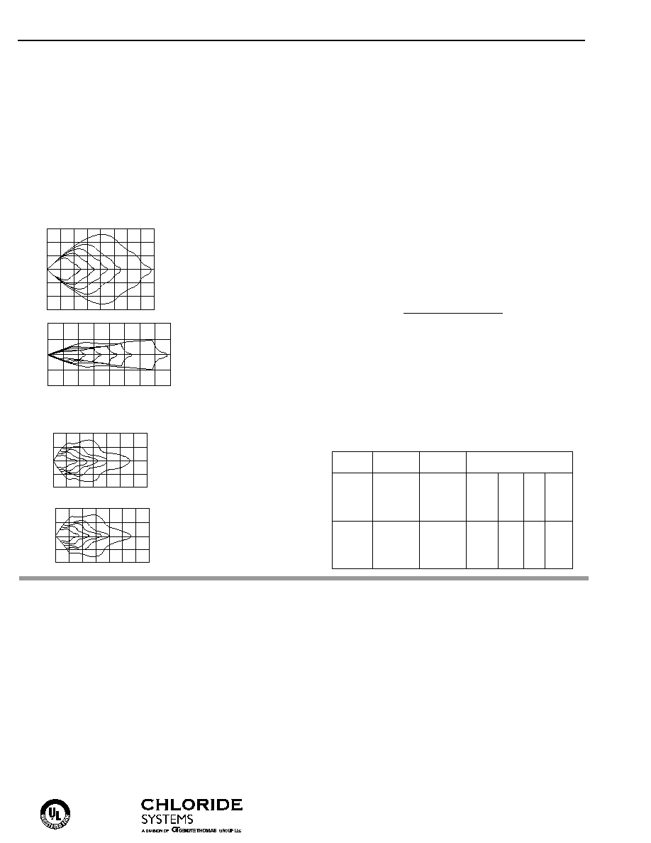
Lamp Head Photometrics
(For DL, suggested head for CCL)
(For DK, suggested head for TCL)
Operation
DC
Suggested
Watts to 87
1
/
2
Voltage
Unit
Lamp Head
of Rated Voltage*
1
1
/
2
hrs. 2 hrs. 4 hrs. 8 hrs.
6
CCL75
DL
75
56
28.5
15
CCL100
DL
100
75
38
20
CCL150
DL
150
112.5
57
30
CCL225
DL
225
169
85.5
45
12
TCL150
DK
150
112.5
57
30
TCL200
DK
200
150
96
34
TCL300
DK
300
225
114
60
TCL450
DK
450
337.5
171
90
Electronics
120/277 VAC dual voltage input with surge-protect-
ed, solid-state charging circuitry provides for a
reliable charging system. The charging system is
furnished with low voltage disconnect, AC lockout,
brownout protection, AC indicator lamp and test
switch.
The low voltage disconnect (LVD) feature will dis-
connect the battery prior to an unacceptable deep
discharge, but not before the required 90 minute
emergency operation.
The AC lockout feature prevents battery drain prior to
the initial energizing of utility power, and allows the
installer to complete all wiring and electrical connec-
tions without energizing the emergency circuit.
The brownout protection circuitry will automatically
switch the unit into the emergency mode if the utility
voltage sags below 20% of nominal.
Battery charging circuitry is entirely solid-state, and
utilizes a fully automatic, voltage regulated charger.
Battery recharge time after full discharge is less than
the required UL 924 standard.
Line sensitive electronics cause an instantaneous
transfer to battery power if utility power is lost, or a
brownout condition is detected. When line voltage is
present and stabilized, the transfer circuitry switches
back to normal operation and begins recharging the
battery. The transfer circuitry can be tested via a
momentary test switch located on the housing.
Vertical
20
30
50
10
0
Up 20
10
feet 0
10
Down 20
.2
.1
40
60
70
.3
1
.5
Horizontal
20
30
50
10
0
Left 20
10
feet 0
10
Right 20
.2
.1
40
60
70
.3
1
.5
20
30
50
10
0
Up 20
10
feet 0
10
Down 20
Photometric No. 3
40
60
70
80
1
.3
.2
.1
.5
Horizontal
20
30
50
10
0
Left 30
10
feet 0
10
20
Right 30
1
.3
.2
.1
20
.5
40
60
70
80