FP15R12KE3ENG_rev6_140202.xls
Technische Information / Technical Information
IGBT-Module
IGBT-Modules
FP15R12KE3
Vorläufig
Preliminary
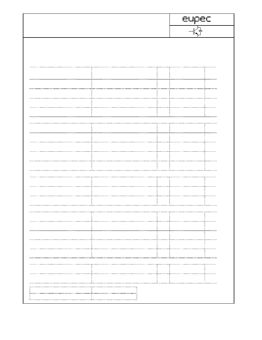
Elektrische Eigenschaften / Electrical properties
Höchstzulässige Werte / Maximum rated values
Diode Gleichrichter/ Diode Rectifier
Periodische Rückw. Spitzensperrspannung
repetitive peak reverse voltage
T
vj
=25°C
V
RRM
1600
V
Durchlaßstrom Grenzeffektivwert pro Chip
RMS forward current per chip
T
C
=80°C
I
FRMSM
25
A
Gleichrichter Ausgang Grenzeffektivstrom
maximum RMS current at Rectifier output
T
C
=80°C
I
RMSmax
36
A
Stoßstrom Grenzwert
t
P
= 10 ms, T
vj
= 25°C
I
FSM
196
A
surge forward current
t
P
= 10 ms, T
vj
= 150°C
158
A
Grenzlastintegral
t
P
= 10 ms, T
vj
= 25°C
I
2
t
192
A
2
s
I
2
t - value
t
P
= 10 ms, T
vj
= 150°C
125
A
2
s
Transistor Wechselrichter/ Transistor Inverter
Kollektor-Emitter-Sperrspannung
collector-emitter voltage
T
vj
=25°C
V
CES
1200
V
Kollektor-Dauergleichstrom
T
C
= 80°C
I
C,nom.
15
A
DC-collector current
T
C
= 25 °C
I
C
27
A
Periodischer Kollektor Spitzenstrom
repetitive peak collector current
t
P
= 1 ms, T
C
=80°C
I
CRM
30
A
Gesamt-Verlustleistung
total power dissipation
T
C
= 25°C
P
tot
89
W
Gate-Emitter-Spitzenspannung
gate-emitter peak voltage
V
GES
+/- 20V
V
Diode Wechselrichter/ Diode Inverter
Dauergleichstrom
DC forward current
I
F
15
A
Periodischer Spitzenstrom
repetitive peak forw. current
t
P
= 1 ms
I
FRM
30
A
Grenzlastintegral
I
2
t - value
V
R
= 0V, t
p
= 10ms, T
vj
= 125°C
I
2
t
44
A
2
s
Transistor Brems-Chopper/ Transistor Brake-Chopper
Kollektor-Emitter-Sperrspannung
collector-emitter voltage
T
vj
=25°C
V
CES
1200
V
Kollektor-Dauergleichstrom
T
C
= 80 °C
I
C,nom.
15
A
DC-collector current
T
C
= 25 °C
I
C
27
A
Periodischer Kollektor Spitzenstrom
repetitive peak collector current
t
P
= 1 ms, T
C
= 80°C
I
CRM
30
A
Gesamt-Verlustleistung
total power dissipation
T
C
= 25°C
P
tot
89
W
Gate-Emitter-Spitzenspannung
gate-emitter peak voltage
V
GES
+/- 20V
V
Diode Brems-Chopper/ Diode Brake-Chopper
Dauergleichstrom
DC forward current
I
F
15
A
Periodischer Spitzenstrom
repetitive peak forw. current
t
P
= 1 ms
I
FRM
30
A
prepared by: Thomas Passe
date of publication: 2002-02-13
approved by: Ingo Graf
revision: 6
1(12)
Technische Information / Technical Information
IGBT-Module
IGBT-Modules
FP15R12KE3
Vorläufig
Preliminary
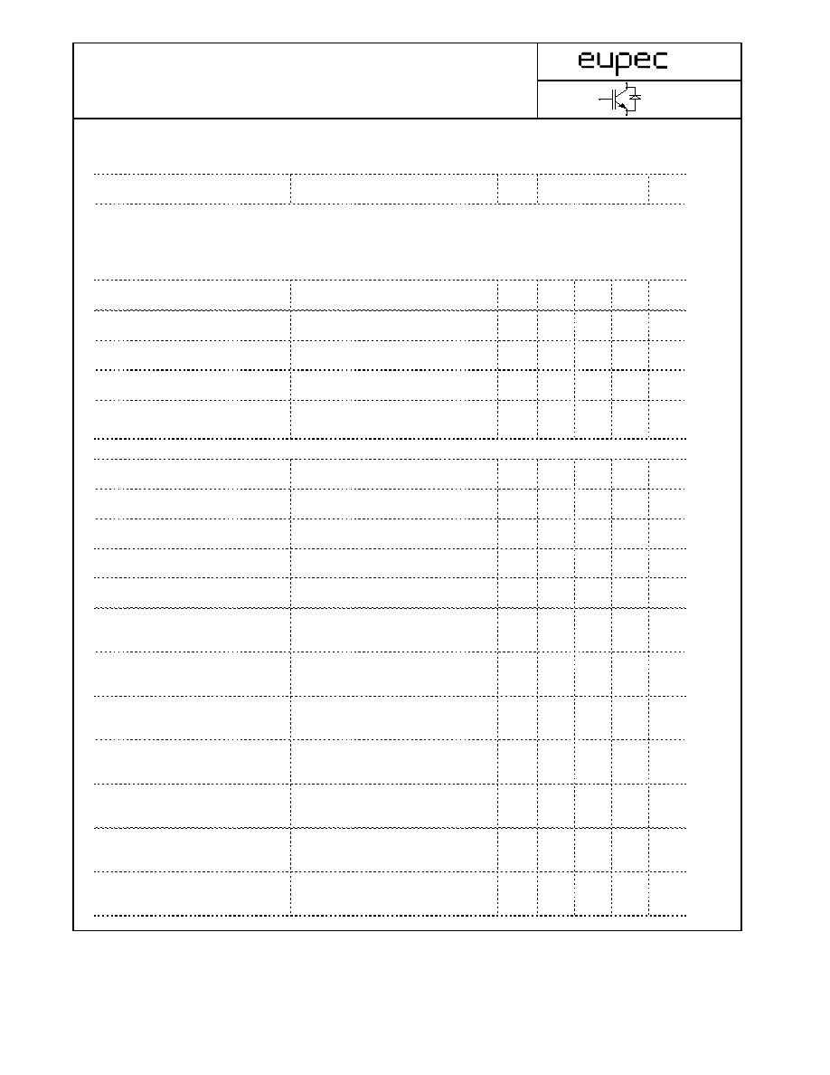
Modul Isolation/ Module Isolation
Isolations-Prüfspannung
insulation test voltage
RMS, f = 50 Hz, t = 1 min.
NTC connected to Baseplate
V
ISOL
2,5
kV
Elektrische Eigenschaften / Electrical properties
Charakteristische Werte / Characteristic values
Diode Gleichrichter/ Diode Rectifier
min.
typ. max.
Durchlaßspannung
forward voltage
T
vj
= 150°C, I
F
= 15 A
V
F
-
1,05
-
V
Schleusenspannung
threshold voltage
T
vj
= 150°C
V
(TO)
-
0,80
-
V
Ersatzwiderstand
slope resistance
T
vj
= 150°C
r
T
-
15
-
m
W
Sperrstrom
reverse current
T
vj
= 150°C, V
R
= 1600 V
I
R
-
5
-
mA
Modul Leitungswiderstand, Anschlüsse-Chip
lead resistance, terminals-chip
T
C
= 25°C
R
AA'+CC'
-
11
-
m
W
Transistor Wechselrichter/ Transistor Inverter
min.
typ. max.
Kollektor-Emitter Sättigungsspannung
V
GE
= 15V, T
vj
= 25°C, I
C
=
15 A
V
CE sat
-
1,7
2,15
V
collector-emitter saturation voltage
V
GE
= 15V, T
vj
= 125°C, I
C
=
15 A
-
2
-
V
Gate-Schwellenspannung
gate threshold voltage
V
CE
= V
GE
, T
vj
= 25°C, I
C
=
0,5mA
V
GE(TO)
4,5
5,5
6,5
V
Eingangskapazität
input capacitance
f = 1MHz, T
vj
= 25°C
V
CE
= 25 V, V
GE
= 0 V
C
ies
-
1,0
-
nF
Kollektor-Emitter Reststrom
collector-emitter cut-off current
Gate-Emitter Reststrom
gate-emitter leakage current
V
CE
= 0V, V
GE
=20V, T
vj
=25°C
I
GES
-
-
400
nA
Einschaltverzögerungszeit (ind. Last)
I
C
= I
Nenn
, V
CC
= 600 V
turn on delay time (inductive load)
V
GE
= ±15V, T
vj
= 25°C, R
G
=
68 Ohm
t
d,on
-
56
-
ns
V
GE
= ±15V, T
vj
= 125°C, R
G
=
68 Ohm
-
57
-
ns
Anstiegszeit (induktive Last)
I
C
= I
Nenn
, V
CC
= 600 V
rise time (inductive load)
V
GE
= ±15V, T
vj
= 25°C, R
G
=
68 Ohm
t
r
-
30
-
ns
V
GE
= ±15V, T
vj
= 125°C, R
G
=
68 Ohm
-
40
-
ns
Abschaltverzögerungszeit (ind. Last)
I
C
= I
Nenn
, V
CC
= 600 V
turn off delay time (inductive load)
V
GE
= ±15V, T
vj
= 25°C, R
G
=
68 Ohm
t
d,off
-
337
-
ns
V
GE
= ±15V, T
vj
= 125°C, R
G
=
68 Ohm
-
421
-
ns
Fallzeit (induktive Last)
I
C
= I
Nenn
, V
CC
=
600 V
fall time (inductive load)
V
GE
= ±15V, T
vj
= 25°C, R
G
=
68 Ohm
t
f
-
66
-
ns
V
GE
= ±15V, T
vj
= 125°C, R
G
=
68 Ohm
-
87
-
ns
Einschaltverlustenergie pro Puls
I
C
= I
Nenn
, V
CC
=
600 V
turn-on energy loss per pulse
V
GE
= ±15V, T
vj
= 125°C, R
G
=
68 Ohm
E
on
-
2,2
-
mWs
L
S
= 80 nH
Abschaltverlustenergie pro Puls
I
C
= I
Nenn
, V
CC
= 600 V
turn-off energy loss per pulse
V
GE
= ±15V, T
vj
= 125°C, R
G
=
68 Ohm
E
off
-
1,6
-
mWs
L
S
= 80 nH
Kurzschlußverhalten
t
P
£ 10µs, V
GE
£ 15V, R
G
=
68 Ohm
SC Data
T
vj
£125°C, V
CC
=
720 V
I
SC
-
68
-
A
-
mA
I
CES
-
5,0
V
GE
= 0V, T
vj
=125°C, V
CE
= 1200V
2(12)
Technische Information / Technical Information
IGBT-Module
IGBT-Modules
FP15R12KE3
Vorläufig
Preliminary
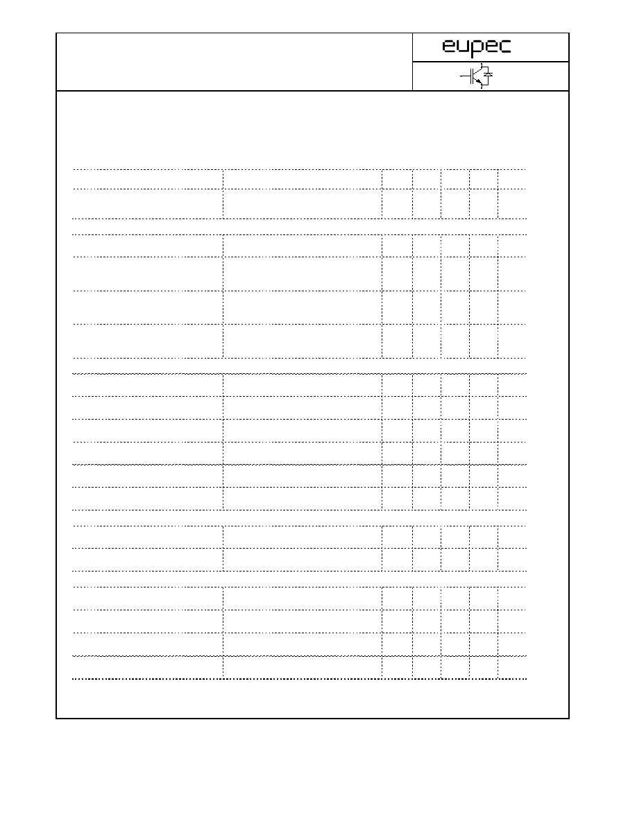
Elektrische Eigenschaften / Electrical properties
Charakteristische Werte / Characteristic values
min.
typ. max.
Modulinduktivität
stray inductance module
L
sCE
-
-
40
nH
Modul Leitungswiderstand, Anschlüsse-Chip
lead resistance, terminals-chip
T
C
= 25°C
R
CC'+EE'
-
14
-
m
W
Diode Wechselrichter/ Diode Inverter
min.
typ. max.
Durchlaßspannung
V
GE
= 0V, T
vj
= 25°C, I
F
=
15 A
V
F
-
1,7
2,1
V
forward voltage
V
GE
= 0V, T
vj
= 125°C, I
F
=
15 A
-
1,7
-
V
Rückstromspitze
I
F
=I
Nenn
, - di
F
/dt = 500 A/us
peak reverse recovery current
V
GE
= -10V, T
vj
= 25°C, V
R
=
600 V
I
RM
-
18
-
A
V
GE
= -10V, T
vj
= 125°C, V
R
=
600 V
-
16
-
A
Sperrverzögerungsladung
I
F
=I
Nenn
, - di
F
/dt = 500 A/us
recovered charge
V
GE
= -10V, T
vj
= 25°C, V
R
=
600 V
Q
r
-
1,6
-
µAs
V
GE
= -10V, T
vj
= 125°C, V
R
=
600 V
-
2,8
-
µAs
Abschaltenergie pro Puls
I
F
=I
Nenn
, - di
F
/dt = 500 A/us
reverse recovery energy
V
GE
= -10V, T
vj
= 25°C, V
R
=
600 V
E
rec
-
0,5
-
mWs
V
GE
= -10V, T
vj
= 125°C, V
R
=
600 V
-
1
-
mWs
Transistor Brems-Chopper/ Transistor Brake-Chopper
min.
typ. max.
Kollektor-Emitter Sättigungsspannung
V
GE
= 15V, T
vj
= 25°C, I
C
=
15,0 A
V
CE sat
-
1,7
2,15
V
collector-emitter saturation voltage
V
GE
= 15V, T
vj
= 125°C, I
C
=
15,0 A
-
2
-
V
Gate-Schwellenspannung
gate threshold voltage
V
CE
= V
GE
, T
vj
= 25°C, I
C
=
0,5mA
V
GE(TO)
4,5
5,5
6,5
V
Eingangskapazität
input capacitance
f = 1MHz, T
vj
= 25°C
V
CE
= 25 V, V
GE
= 0 V
C
ies
-
1,1
-
nF
Kollektor-Emitter Reststrom
-
5,0
-
mA
collector-emitter cut-off current
Gate-Emitter Reststrom
gate-emitter leakage current
V
CE
= 0V, V
GE
= 20V, T
vj
= 25°C
I
GES
-
-
400
nA
Diode Brems-Chopper/ Diode Brake-Chopper
min.
typ. max.
Durchlaßspannung
T
vj
= 25°C, I
F
=
15A
V
F
-
2,05
2,65
V
forward voltage
T
vj
= 125°C, I
F
=
15A
-
2,15
-
V
NTC-Widerstand/ NTC-Thermistor
min.
typ. max.
Nennwiderstand
rated resistance
T
C
= 25°C
R
25
-
5
-
k
W
Abweichung von R
100
deviation of R
100
T
C
= 100°C, R
100
= 493
W
DR/R
-5
5
%
Verlustleistung
power dissipation
T
C
= 25°C
P
25
20
mW
B-Wert
B-value
R
2
= R
1
exp [B(1/T
2
- 1/T
1
)]
B
25/50
3375
K
V
GE
= 0V, T
vj
= 125°C, V
CE
= 1200V
3(12)
Technische Information / Technical Information
IGBT-Module
IGBT-Modules
FP15R12KE3
Vorläufig
Preliminary
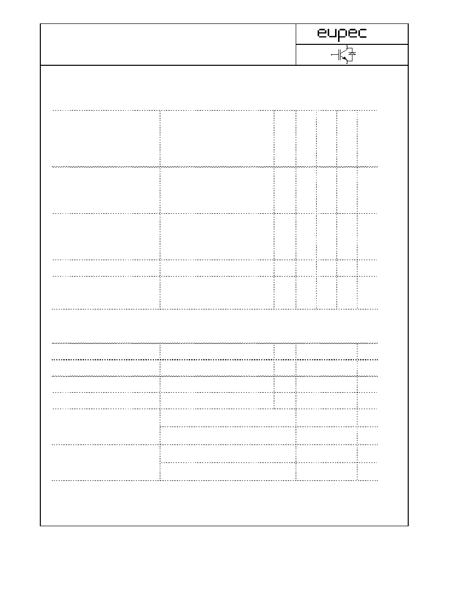
Thermische Eigenschaften / Thermal properties
min.
typ. max.
Innerer Wärmewiderstand
Gleichr. Diode/ Rectif. Diode
l
Paste
=1W/m*K
R
thJH
-
1,9
-
K/W
thermal resistance, junction to heatsink
Trans. Wechsr./ Trans. Inverter
l
grease
=1W/m*K
-
1,6
-
K/W
Diode Wechsr./ Diode Inverter
-
3,2
-
K/W
Trans. Bremse/ Trans. Brake
-
1,6
-
K/W
Diode Bremse/ Diode Brake
-
4,0
-
K/W
Innerer Wärmewiderstand
Gleichr. Diode/ Rectif. Diode
R
thJC
-
-
1,9
K/W
thermal resistance, junction to case
Trans. Wechsr./ Trans. Inverter
-
-
1,4
K/W
Diode Wechsr./ Diode Inverter
-
-
2,4
K/W
Trans. Bremse/ Trans. Brake
-
-
1,4
K/W
Diode Bremse/ Diode Brake
-
-
2,9
K/W
Übergangs-Wärmewiderstand
Gleichr. Diode/ Rectif. Diode
l
Paste
=1W/m*K
R
thCH
-
0,2
-
K/W
thermal resistance, case to heatsink
Trans. Wechsr./ Trans. Inverter
l
grease
=1W/m*K
-
0,3
-
K/W
Diode Wechsr./ Diode Inverter
-
1
-
K/W
Trans. Bremse/ Trans. Brake
-
0,3
-
K/W
Diode Bremse/ Diode Brake
-
1,4
-
K/W
Höchstzulässige Sperrschichttemperatur
maximum junction temperature
T
vj
-
-
150
°C
Betriebstemperatur
operation temperature
T
op
-40
-
125
°C
Lagertemperatur
storage temperature
T
stg
-40
-
125
°C
Mechanische Eigenschaften / Mechanical properties
Innere Isolation
internal insulation
Al
2
O
3
CTI
comperative tracking index
225
Anpreßkraft f. mech. Befestigung
F
N
mounting force
Gewicht
weight
G
36
g
Kriechstrecke
creeping distance
13,5
mm
Luftstrecke
clearance
12
mm
Kriechstrecke
creeping distance
7,5
mm
Luftstrecke
clearance
7,5
mm
Terminal - Terminal
terminal - terminal
40...80
Kontakt - Kühlkörper
terminal to heatsink
4(12)
Technische Information / Technical Information
IGBT-Module
IGBT-Modules
FP15R12KE3
Vorläufig
Preliminary
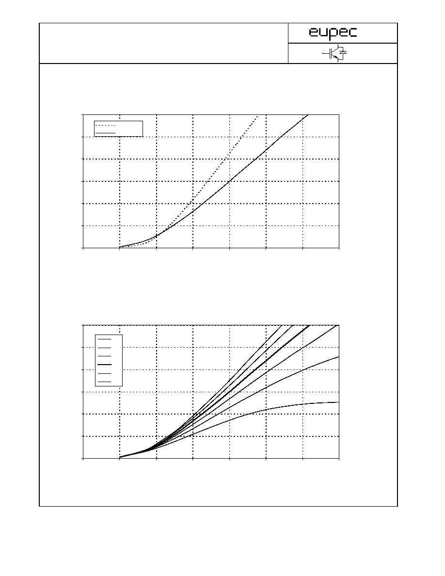
I
C
[A
]
V
CE
[V]
I
C
[A
]
V
CE
[V]
Ausgangskennlinienfeld Wechselr. (typisch) I
C
= f (V
CE
)
Output characteristic Inverter (typical)
V
GE
= 15 V
0
5
10
15
20
25
30
0,00
0,50
1,00
1,50
2,00
2,50
3,00
3,50
Tj = 25°C
Tj = 125°C
0
5
10
15
20
25
30
0,00
0,50
1,00
1,50
2,00
2,50
3,00
3,50
9V
11V
13V
15V
17V
19V
Ausgangskennlinienfeld Wechselr. (typisch) I
C
= f (V
CE
)
Output characteristic Inverter (typical)
T
vj
= 125°C
5(12)