N
Netz-Thyristor
Phase Control Thyristor
Datenblatt / Data sheet
T 1451N
BIP AM / SM PB, 2001-02-06, Przybilla J. / Keller
2/8
Seite/page
Thermische Eigenschaften
Mechanische Eigenschaften
Elektrische Eigenschaften / Electrical properties
Charakteristische Werte / Characteristic values
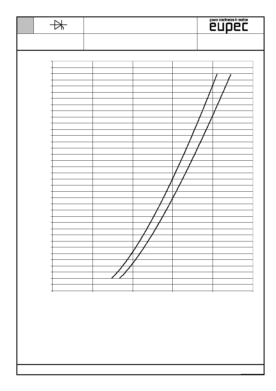
Freiwerdezeit
circuit commutated turn-off time
T
vj
= T
vj max
, i
TM
= I
TAVM
v
RM
= 100 V, v
DM
= 0,67 V
DRM
dv
D
/dt = 20 V/µs, -di
T
/dt = 10 A/µs
4.Kennbuchstabe / 4
th
letter O
t
q
typ. 450
µs
Sperrverzˆgerungsladung
recovered charge
T
vj
= T
vj max
i
TM
= I
TAVM
, -di
T
/dt = 10 A/µs
V
R
= 0,5V
RRM
, V
RM
= 0,8V
RRM
Q
r
max. 15
mAs
R¸ckstromspitze
peak reverse recovery current
T
vj
= T
vj max
i
TM
= I
TAVM
, -di
T
/dt = 10 A/µs
V
R
= 0,5V
RRM
, V
RM
= 0,8V
RRM
I
RM
max. 320
A
Thermische Eigenschaften / Thermal properties
Innerer W‰rmewiderstand
thermal resistance, junction to case
K¸hlfl‰che / cooling surface
beidseitig / two-sided, = 180∞sin
beidseitig / two-sided, DC
Anode / anode, DC
Kathode / cathode, DC
R
thJC
max.
max.
max.
max.
0,0097
0,009
0,014
0,0250
∞C/W
∞C/W
∞C/W
∞C/W
Ðbergangs-W‰rmewiderstand
thermal resistance, case to heatsink
K¸hlfl‰che / cooling surface
beidseitig / two-sided
einseitig / single-sided
R
thCH
max.
max.
0,0025
0,005
∞C/W
∞C/W
Hˆchstzul‰ssige Sperrschichttemperatur
maximum junction temperature
T
vj max
125 ∞C
Betriebstemperatur
operating temperature
T
c op
-40...+125
∞C
Lagertemperatur
storage temperature
T
stg
-40...+150
∞C
Mechanische Eigenschaften / Mechanical properties
Geh‰use, siehe Anlage
case, see annex
Seite
3
page 3
Si-Element mit Druckkontakt
Si-pellet with pressure contact
Anpresskraft
clamping force
F
36...52
kN
Steueranschl¸sse
control terminals
DIN 46244 Gate
Kathode /Cathode
A
4,8x0,8
A 6,3x0,8
Gewicht
weight
G
typ.
1500 g
Kriechstrecke
creepage distance
33 mm
Schwingfestigkeit
vibration resistance
f = 50 Hz
50 m/s≤
Mit diesem Datenblatt werden Halbleiterbauelemente spezifiziert, jedoch keine Eigenschaften zugesichert. Sie gilt in
Verbindung mit den zugehˆrigen technischen Erl‰uterungen.
This data sheet specifies semiconductor devices, but promises no characteristics. It is valid in combination with the belonging
technical notes.
N
Netz-Thyristor
Phase Control Thyristor
Datenblatt / Data sheet
T 1451N
BIP AM / SM PB, 2001-02-06, Przybilla J. / Keller
4/8
Seite/page
R,t ≠ Werte
R
R,T-Werte
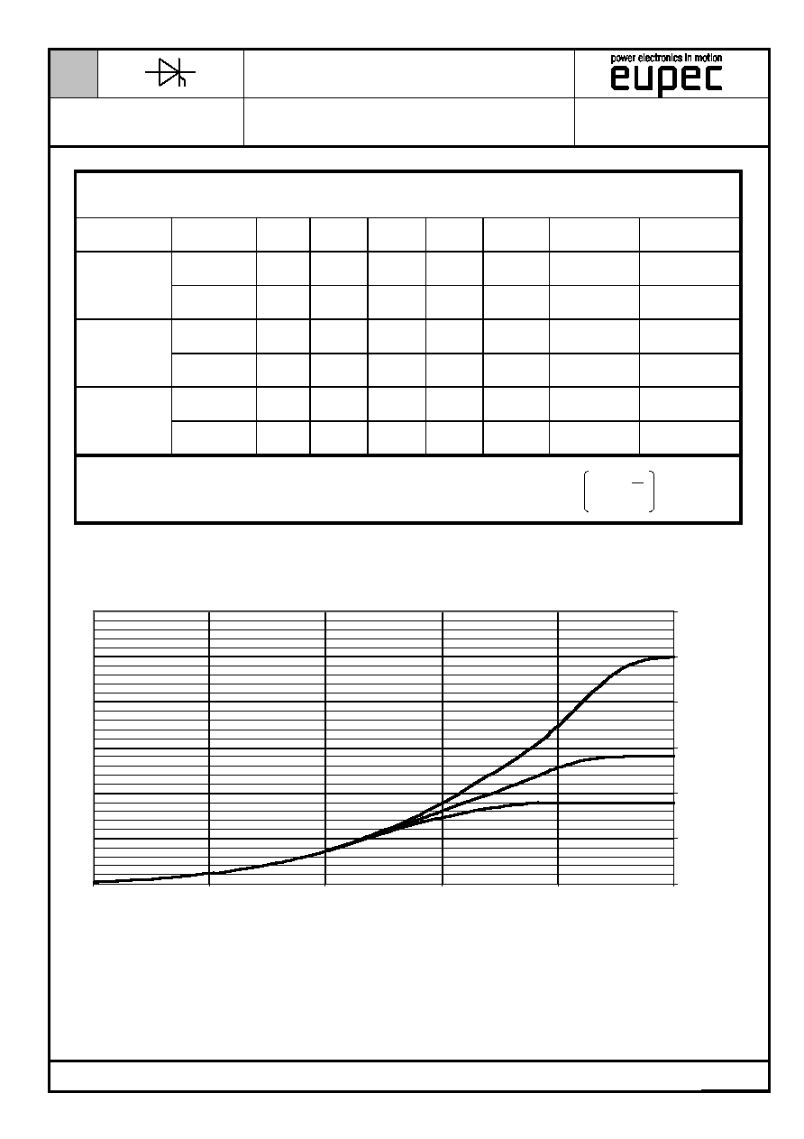
Analytische Elemente des transienten W‰rmewiderstandes Z
thJC
Analytical elements of transient thermal impedance Z
thJC
Pos.
n
1
2
3
4
5
6
7
R
thn
[∞C/W] 0,00223 0,0027
0,0028 0,0008 0,00047
beidseitig
two-sided
n
[s]
2,18
0,44
0,11 0,015 0,0041
R
thn
[∞C/W] 0,00623 0,0037
0,0028 0,0008 0,00047
anodenseitg
anode-sided
n
[s]
6,1
0,6
0,11 0,015 0,0041
R
thn
[∞C/W] 0,01503 0,0059
0,0028 0,0008 0,00047
kathodenseitig
cathode-sided
n
[s]
14,7
0,96
0,11 0,015 0,0041
Analytische Funktion / Analytical function:
-
=
max
n
n=1
thn
thJC
n
-t
e
1
R
Z
0
0 ,0 0 5
0 ,0 1
0 ,0 1 5
0 ,0 2
0 ,0 2 5
0 ,0 3
0 ,0 0 1
0 ,0 1
0 ,1
1
1 0
1 0 0
t [ s ]
Z
th JC
[K/W
]
c
a
d
Transienter innerer W‰rmewiderstand f¸r DC/ Transient thermal impedance Z
thJC
= f(t) for DC
Beidseitige K¸hlung / Two-sided cooling
Anodenseitige K¸hlung / Anode-sided cooling
Kathodenseitige K¸hlung / Cathode-sided cooling