 | –≠–ª–µ–∫—Ç—Ä–æ–Ω–Ω—ã–π –∫–æ–º–ø–æ–Ω–µ–Ω—Ç: T2476N | –°–∫–∞—á–∞—Ç—å:  PDF PDF  ZIP ZIP |

Technische Information / Technical Information
Netz-Thyristor
Phase Control Thyristor
T 2476 22...28
N
Elektrische Eigenschften / Electrical properties
Vorl‰ufige Daten
Hˆchstzul‰ssige Werte / Maximum rated values
Preliminary Data
Periodische Vorw‰rts- und R¸ckw‰rts-Spitzensperrspannung
T
vj
= - 40∞C...T
vj max
V
DRM
, V
RRM
2200, 2400
V
repetitive peak forward off-state and reverse voltages
2600, 2800
Vorw‰rts-Stoþspitzensperrspannung
T
vj
= - 40∞C...T
vj max
V
DSM
2200, 2400
V
non-repetitive peak foward off-state voltage
2600, 2800
R¸ckw‰rts-Stoþspitzensperrspannung
T
vj
= + 25∞C...T
vj max
V
RSM
2300, 2500
V
non-repetitive peak reverse voltage
2700, 2900
Durchlaþstrom-Grenzeffektivwert
I
TRSMSM
5100
A
RMSM on-state current
Dauergrenzstrom
T
C
= 85∞C
I
TAVM
2476
A
average on-state current
T
C
= 65∞C
3250
A
Stoþstrom-Grenzwert
T
vj
= 25∞C, t
p
= 10 ms
I
TSM
47500
A
1)
surge current
T
vj
= T
vj max
, t
p
= 10 ms
43500
A
Grenzlastintegral
T
vj
= 25∞C, t
p
= 10ms
I≤t
11045
A≤s*10≥
I≤t-value
T
vj
= T
vj max
, t
p
= 10ms
9460
A≤s*10≥
Kritische Stromsteilheit
DIN IEC 747-6
(di
T
/dt)
cr
200
A/µs
critical rate of rise of on-state current
f=50 Hz, v
L
= 10V, i
GM
= 1 A
di
G
/dt = 1 A/µs
Kritische Spannungssteilheit
T
vj
= T
vj max
, v
D
= 0,67 V
DRM
(dv
D
/dt)
cr
1000
V/µs
critical rate of rise of off-state voltage
5.Kennbuchstabe / 5th letter F
Charakteristische Werte / Characteristic values
Durchlaþspannung
T
vj
= T
vj max
, i
T
= 6500 A
v
T
max.
2,00
V
on-state voltage
T
vj
= T
vj max
, i
T
= 3000 A
max.
1,43
V
Schleusenspannung
T
vj
= T
vj max
V
T(TO)
0,95
V
threshold voltage
Ersatzwiderstand
T
vj
= T
vj max
r
T
0,154
m
slope resistance
Durchlaþkennlinie
T
vj
= T
vj max
A=0,8249
on-state voltage
B=1,398E-04
v
T
= A + B x i
T
+ C x ln (i
T
+ 1 ) + D x
i
T
C=8,03563E-03
D=2,4542E-03
Z¸ndstrom
T
vj
= 25∞C, v
D
= 6 V
I
GT
max.
250
mA
gate trigger current
Z¸ndspannung
T
vj
= 25∞C, v
D
= 6V
V
GT
max.
2,5
V
gate trigger voltage
Nicht z¸ndener Steuerstrom
T
vj
= T
vj max
, v
D
= 6 V
I
GD
max.
10
mA
gate non-trigger current
T
vj
= T
vj max
,v
D
= 0,5 V
DRM
max.
5
mA
Nicht z¸ndene Steuerspannung
T
vj
= T
vj max
,v
D
= 0,5 V
DRM
V
GD
max.
0,25
mV
gate non-trigger voltage
Haltestrom
T
vj
= 25∞C, v
D
= 6 V, R
A
= 5
I
H
max.
300
mA
holding current
Einraststrom
T
vj
= 25∞C, v
D
= 6 V, R
GK
>= 10
I
L
max.
1500
mA
latching current
i
GM
= 1 A, di
G
/dt = 1 A/µs
t
g
= 20 µs
Vorw‰rts- und R¸ckw‰rts-Sperrstrom
T
vj
= T
vj max
i
D
, i
R
max.
250
mA
forward off-state and reverse currents
v
D
= V
DRM
, v
R
= V
RRM
Z¸ndverzug
DIN IEC 747-6
t
gd
max.
4
µs
gate controlled delay time
T
vj
= 25∞C
i
GM
= 1 A, di
G
/dt = 1 A/µs
1)
Geh‰usegrenzstrom 38 kA (50Hz Sinushalbwelle). / Current limit of case 38kA (50 Hz sinusodial half-wave)
SZ-M / 01.06.99 , K.-A. R¸ther
A 110/99
Seite/page 1

Technische Information / Technical Information
Netz-Thyristor
Phase Control Thyristor
T 2476 22...28
N
Elektrische Eigenschften / Electrical properties
Vorl‰ufige Daten
Charakteristische Werte / Characteristic values Preliminary Data
Freiwerdezeit
T
vj
= T
vj max
, i
TM
=I
TAVM
t
q
circuit commutatet turn-off time
v
RM
=100V, v
DM
= 0,67 V
DRM
dv
D
/dt = 20 V/µs, -di
T
/dt = 10 Aµs
4. Kennbuchstabe / 4th letter O
typ. 400 µs
Thermische Eigenschaften / Thermal properties
Innerer W‰rmewiderstand
K¸hlfl‰che / cooling surface
R
thJC
thermal resitance, junction to case
beidseitig / two-sided,
=180∞sin
max. 0,0085 ∞C/W
beidseitig / two-sided, DC
max. 0,0078 ∞C/W
Anode / anode,
=
180∞sin
max. 0,0152 ∞C/W
Anode / anode, DC
max. 0,0146 ∞C/W
Kathode / cathode,
=
180∞sin
max. 0,0183 ∞C/W
Kathode / cathode, DC
max. 0,0169 ∞C/W
Ðbergangs- W‰rmewiderstand
K¸hlfl‰che / cooling surface
R
thCK
thermal resitance, case to heatsink
beidseitig / two-sided
max. 0,0025 ∞C/W
einseitig / single-sided
max. 0,0050 ∞C/W
Hˆchstzul‰ssige Sperrschichttemperatur T
vj max
125 ∞C
max. junction temperature
Betriebstemperatur T
c op
-40...125 ∞C
operating temperature
Lagertemperatur T
stg
-40...150 ∞C
storage temperature
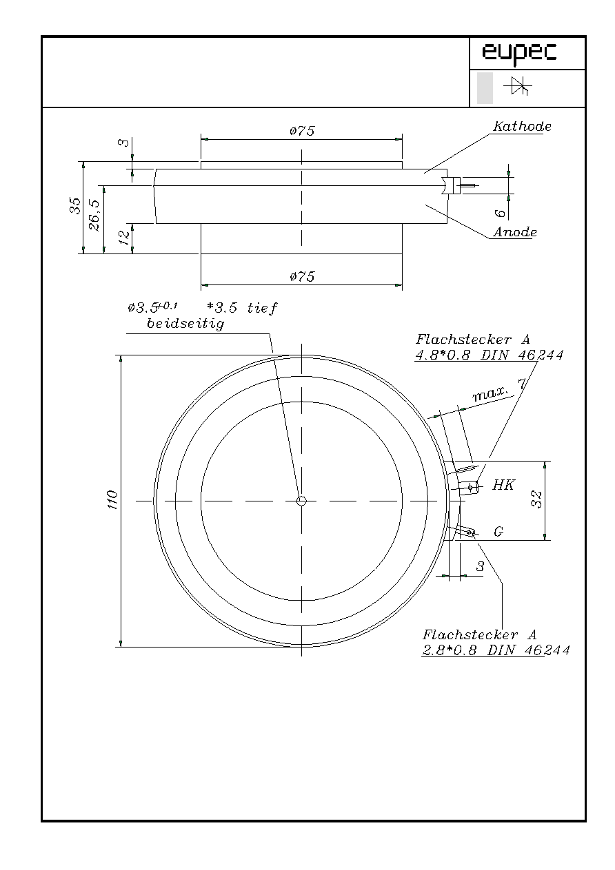
Mechanische Eigenschaften / Mechanical properties
Geh‰use, siehe Anlage Seite 3
case, see appendix page 3
Si-Element mit Druckkontakt, Amplifying-Gate
Si-pellet with pressure contact, amplifying gate
Anpreþkraft F 42...95 kN
clamping force
Gewicht G typ. 1450 g
weight
Kriechstrecke 30 mm
creepage distance
Feuchteklasse
DIN 40040
C
humidity classification
Schwingfestigkeit
f = 50Hz
50 m/s≤
vibration resistance
Mit dieser technischen Information werden Halbleiterbauelemente spezifiziert, jedoch keine Eigenschaften zugesichert. Sie gilt
in Verbindung mit den zugehˆrigen Technischen Erl‰uterungen./ This technical Information specifies semiconductor devices but
promises no characteristics. It is valid in combination with the belonging technical notes.
SZ-M / 01.06.99 , K.-A. R¸ther A 110/99 Seite/page 2
Technische Information / Technical Information
Netz-Thyristor
Phase Control Thyristor
T 2476 N 22 ... 28
N
SZ-M / 01.06.99 , K.-A. R¸ther
A 110/99
Zn. Nr.: 1
Seite/page 3

Technische Information / Technical Information
Netz-Thyristor
Phase Control Thyristor
T 2476 N 22 ... 28
N
K¸hlung
Analytische Elemente des transienten W‰rmewiderstandes Z
thJC
f¸r DC
cooling
Analytical ementes of transient thermal impedance Z
thJC
for DC
Pos.n
1
2
3
4
5
6
7
beidseitig
R
thn
[∞C/W]
0,000030
0,00039 0,00123
0,0028 0,00338
two-sided
n
[s]
0,000055
0,00392
0,0152
0,2068
1,0914
anodenseitig
R
thn
[∞C/W]
0,000009 0,000371
0,0019
0,0013 0,00434 0,00668
anode-sided
n
[s]
0,000010 0,001820 0,00951
0,135
0,347 1,54
kathodenseitig
R
thn
[∞C/W]
0,000032 0,000728 0,00302 0,00802
0,0051
cathode-sided
n
[s]
0,000035
0,00341
0,0215
0,135
1,11
n
max
Analytische Funktion / analytical function : Z
thJC
=
R
thn
( 1 - EXP ( - t /
n
))
n=1
SZ-M / 01.06.99 , K.-A. R¸ther
A 110/99
Seite/page 4
Technische Information / Technical Information
Netz-Thyristor
Phase Control Thyristor
T 2476 N 22...28
N
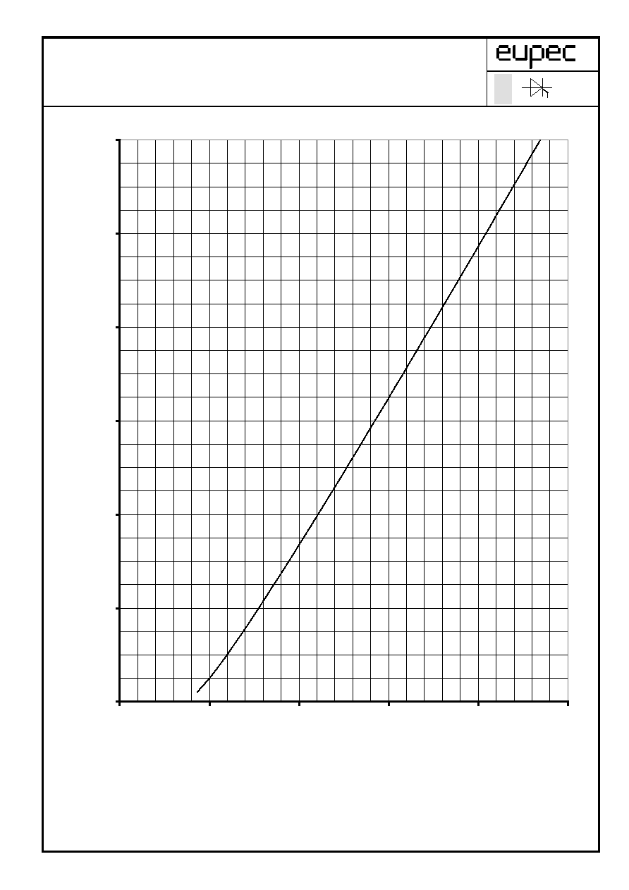
Grenzdurchlaþkennlinie / Limiting on-state characteristic i
T
= f(v
T
)
T
vj
= 125 ∞C
SZ-M / 01.06.99 , K.-A. R¸ther
A 110/99
Z. Nr.: 2
Seite/page 5
0
2.000
4.000
6.000
8.000
10.000
12.000
0,5
1
1,5
2
2,5
3
v
T
[V]
i
T
[A]
Technische Information / Technical Information
Netz-Thyristor
Phase Control Thyristor
T 2476 N 22... 28
N
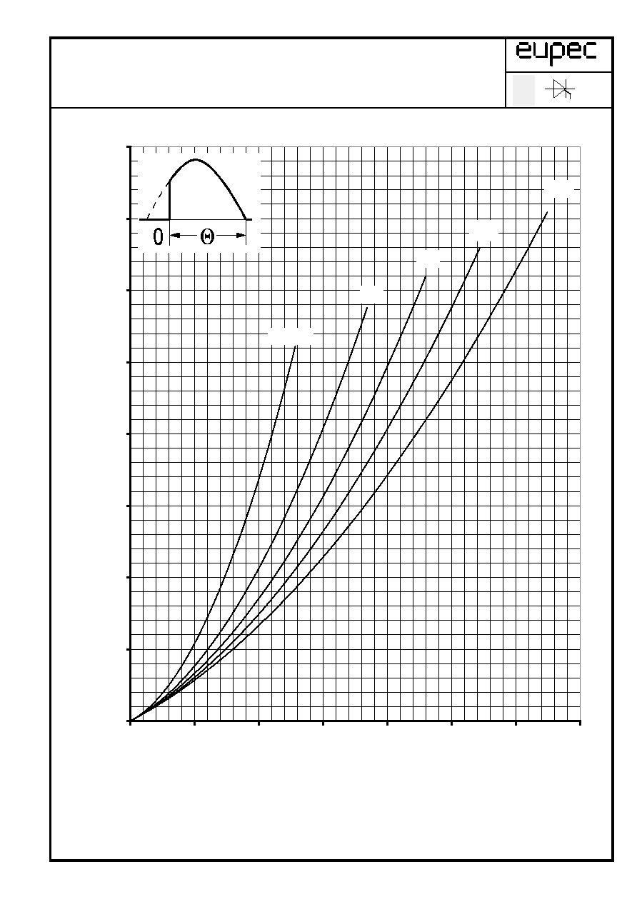
Durchlaþverlustleistung / On-state power loss P
TAV
= f(I
TAV
)
Parameter: Stromfluþwinkel
/ current conduction angle
SZ-M / 01.06.99 , K.-A. R¸ther
A 110/99
Z.Nr.: 3
Seite/page 6
0
1000
2000
3000
4000
5000
6000
7000
8000
0
500
1000
1500
2000
2500
3000
3500
I
TAV
[A]
P
TAV
[W]
= 30∞
60∞
90∞
120∞
180∞
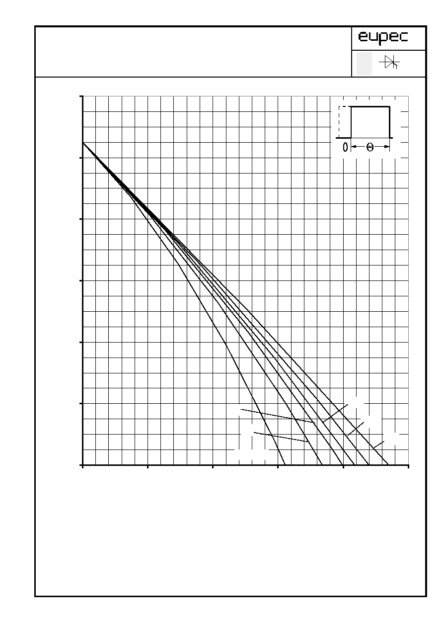
Technische Information / Technical Information
Netz-Thyristor
Phase Control Thyristor
T 2476 N 22...28
N
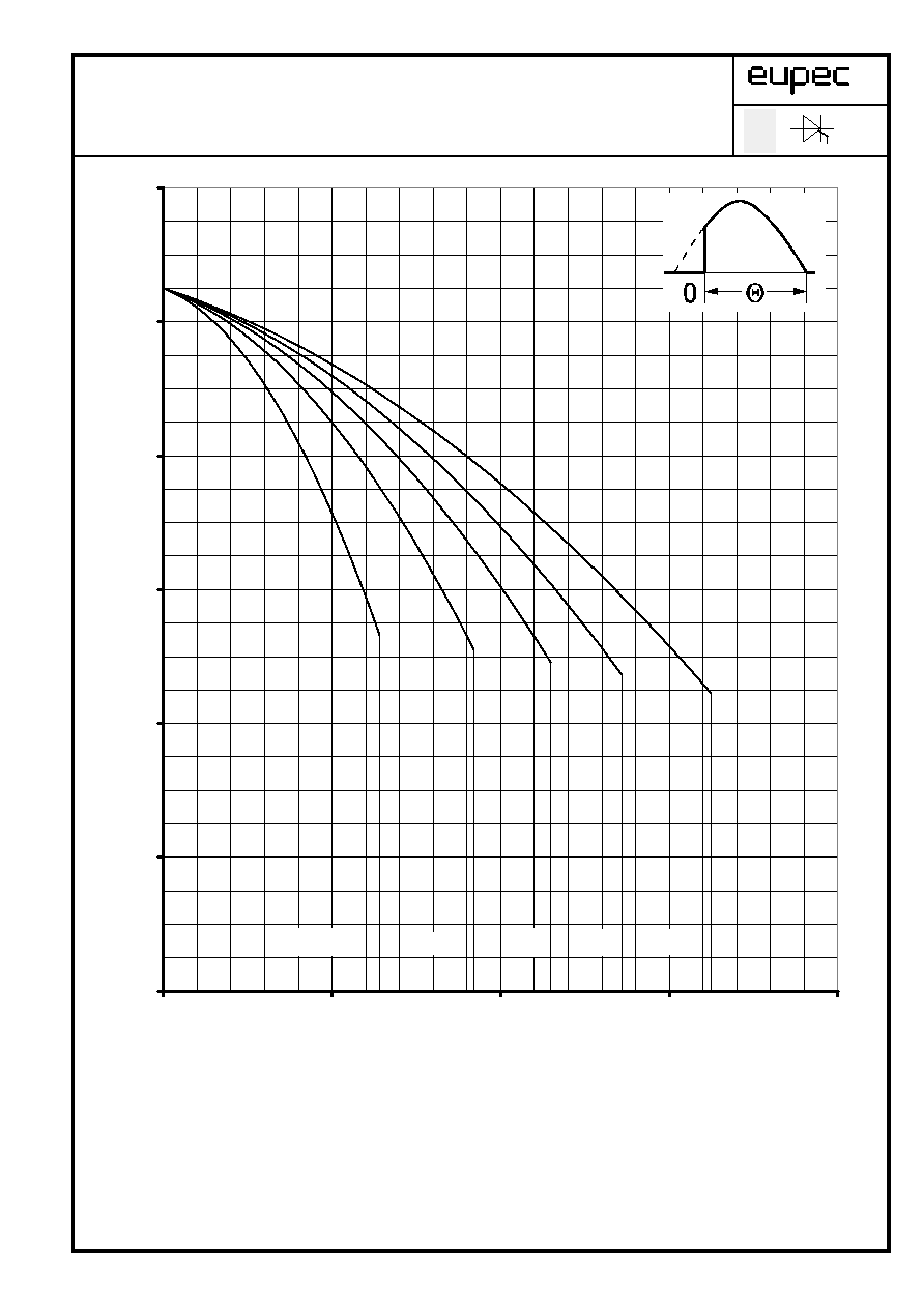
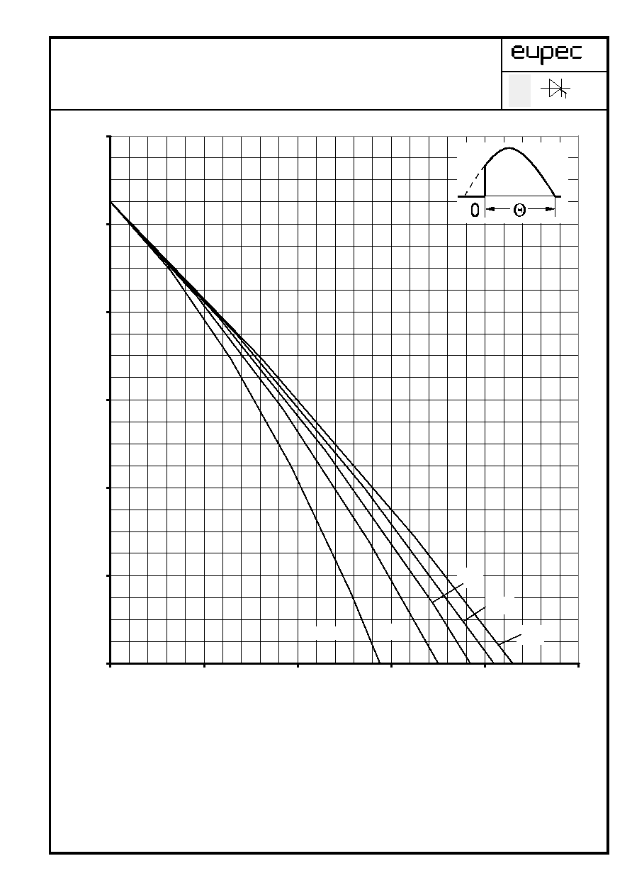
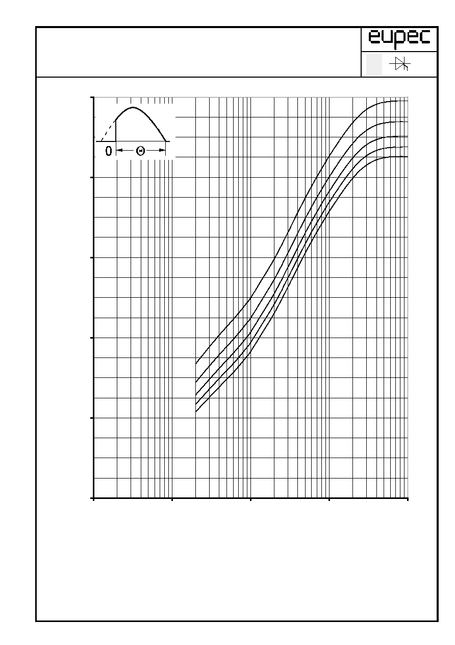
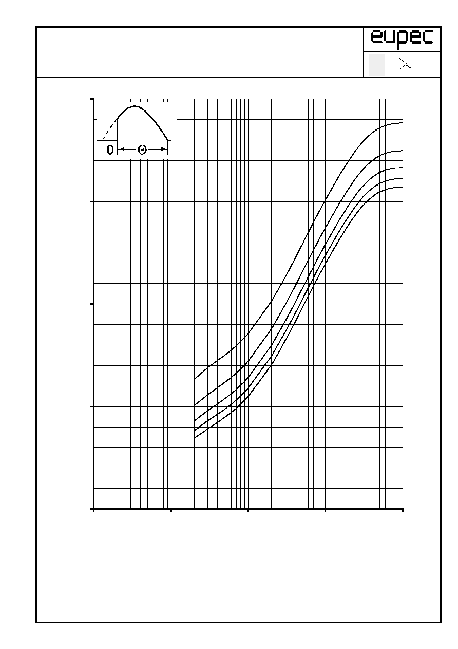
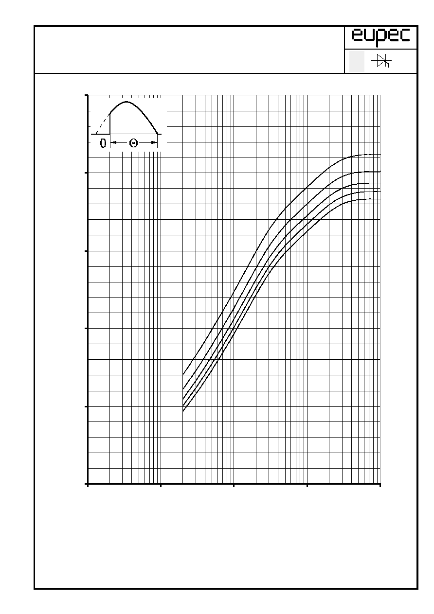
Hˆchstzul‰ssige Geh‰usetemperatur / Maximum allowable case temperature T
C
=f(I
TAVM
)
Beidseitige K¸hlung / Two sided cooling
Parameter: Stromfluþwinkel
/ current conduction angle
Berechnungsgrundlage P
TAV
( Schaltverluste gesondert ber¸cksichtigen)
Calculation base P
TAV
(switching losses shold be considered separately)
SZ-M / 01.06.99 , K.-A. R¸ther
A 110/99
Z.Nr.: 4
Seite/page 7
20
40
60
80
100
120
140
0
1000
2000
3000
4000
I
TAVM
[A]
T
C
[∞C]
= 30∞
60∞
90∞
120∞
180∞
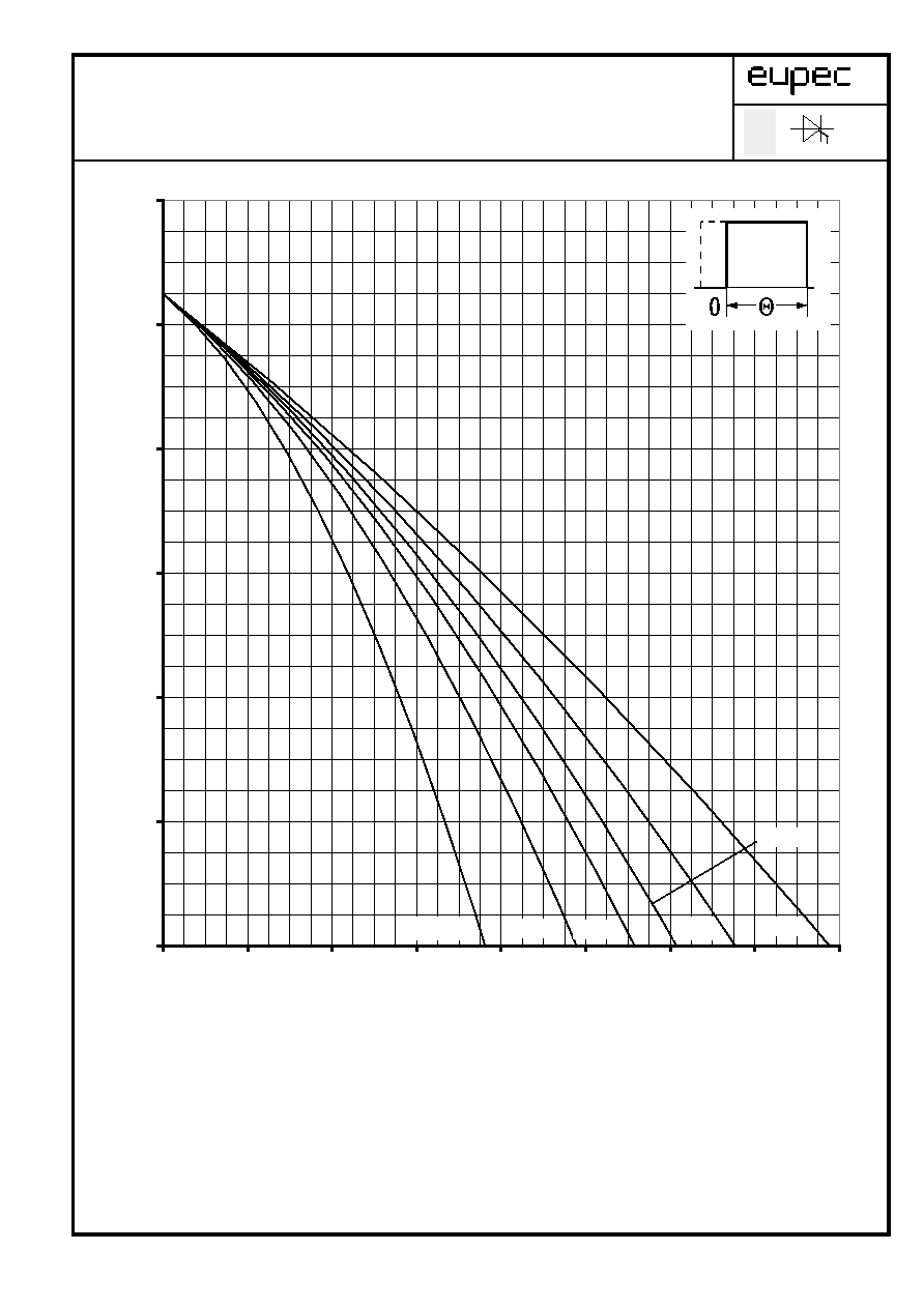
Technische Information / Technical Information
Netz-Thyristor
Phase Control Thyristor
T 2476 N 22... 28
N
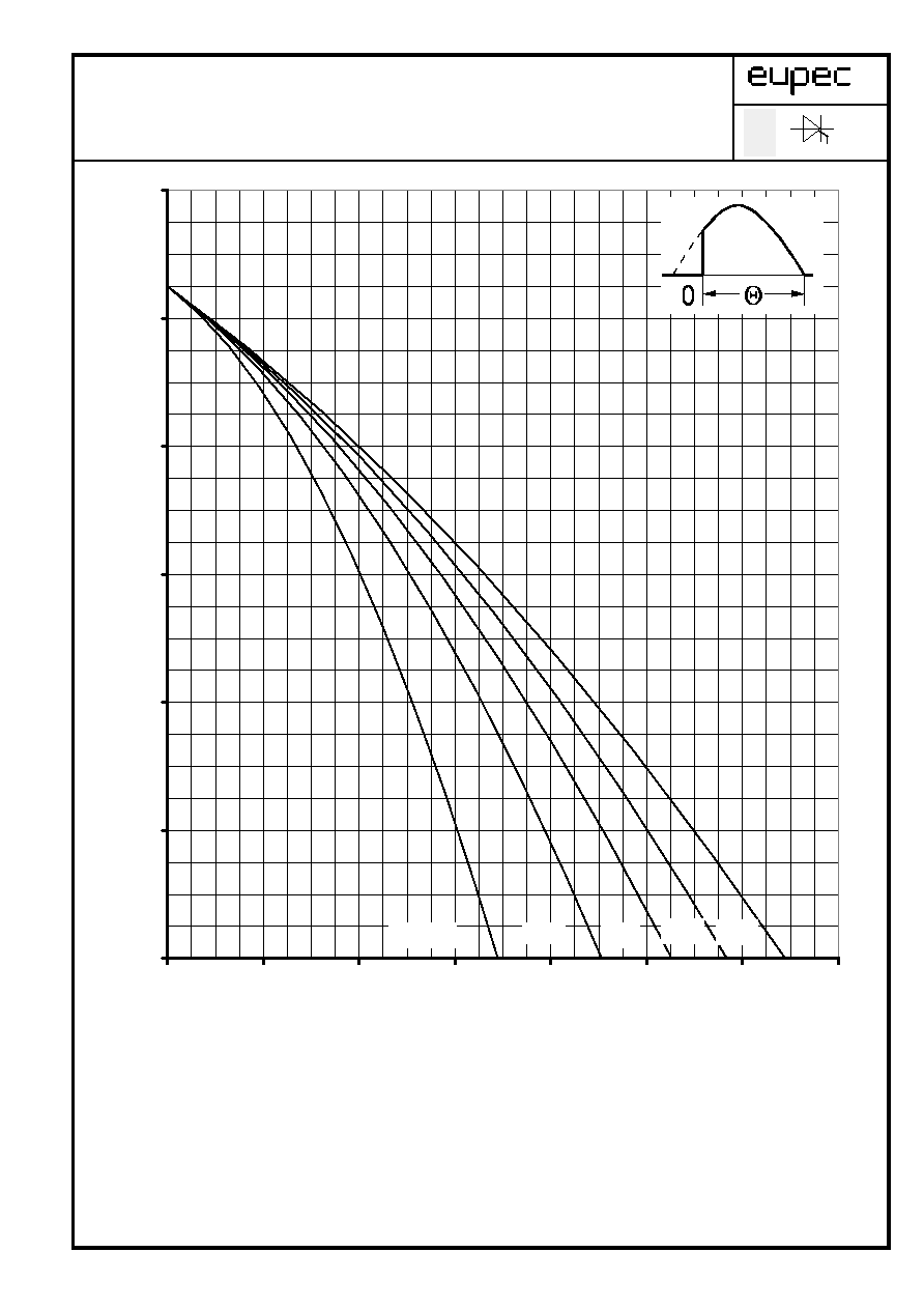
Hˆchstzul‰ssige K¸hlmitteltemperatur / Max. allowable cooling medium temperature T
A
= f (I
TAVM
)
Luftselbstk¸hlung / Natural air-cooling
Parameter: Stromfluþwinkel
/ current conduction angle
Berechnungsgrundlage P
TAV
( Schaltverluste gesondert ber¸cksichtigen)
Calculation base P
TAV
(switching losses shold be considered separately)
SZ-M / 01.06.99 , K.-A. R¸ther
A 110/99
Z.Nr.: 5
Seite/page 8
K¸hlkˆrper / Heatsink. K 0.48 F
20
40
60
80
100
120
140
0
100
200
300
400
500
I
TAVM
[A]
T
A
[∞C]
= 30∞
60∞
90∞
120∞
180∞
Technische Information / Technical Information
Netz-Thyristor
Phase Control Thyristor
T 2476 N 22...28
N
Hˆchstzul‰ssige K¸hlmitteltemperatur / Max. allowable cooling medium temperature T
A
= f (I
TAVM
)
Verst‰rkte Luftk¸hlung / Forced air-cooling
Parameter: Stromfluþwinkel
/ current conduction angle
Berechnungsgrundlage P
TAV
( Schaltverluste gesondert ber¸cksichtigen)
Calculation base P
TAV
(switching losses shold be considered separately)
SZ-M / 01.06.99 , K.-A. R¸ther
A 110/99
Z.Nr.: 6
Seite/page 9
K¸hlkˆrper / Heatsink. K 0.48F, V
L
= 120 l/s
20
40
60
80
100
120
140
0
200
400
600
800
1000
1200
1400
I
TAVM
[A]
T
A
[∞C]
= 30∞
60∞
90∞
120∞
180∞
Technische Information / Technical Information
Netz-Thyristor
Phase Control Thyristor
T 2476 N 22 ... 28
N
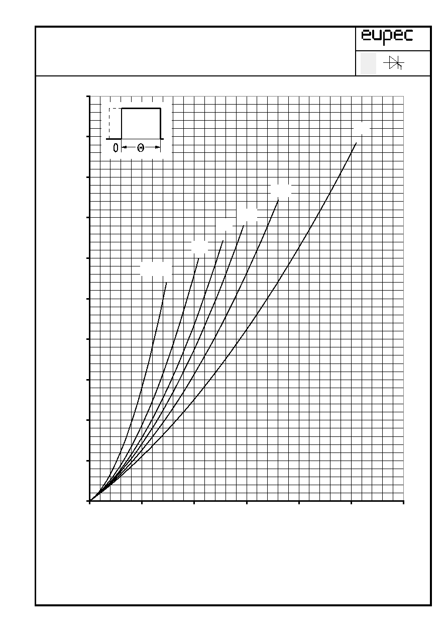
Durchlaþverlustleistung / On-state power loss P
TAV
= f(I
TAV
)
Parameter: Stromfluþwinkel
/ Current conduction angle
SZ-M / 01.06.99 , K.-A. R¸ther
A 110/99
Z.Nr.: 7
Seite/page 10
0
1000
2000
3000
4000
5000
6000
7000
8000
9000
10000
0
1000
2000
3000
4000
5000
6000
I
TAV
[A]
P
TAV
[W]
DC
180∞
120∞
90∞
60∞
= 30∞
Technische Information / Technical Information
Netz-Thyristor
Phase Control Thyristor
T 2476 N 22...28
N
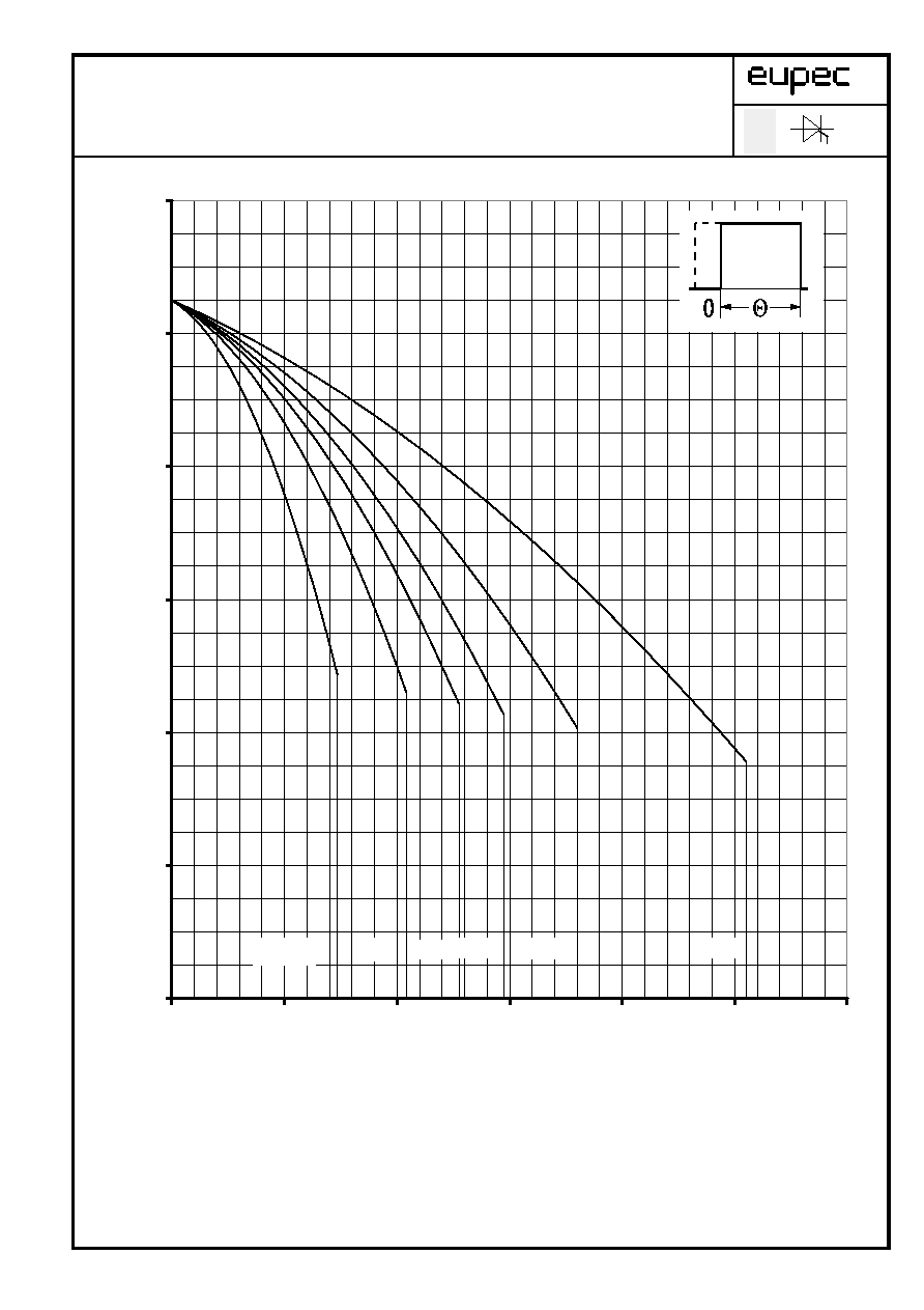
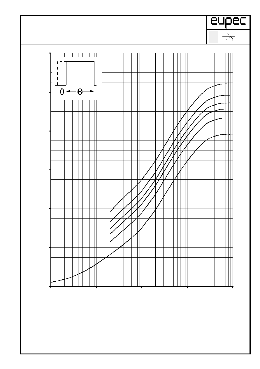
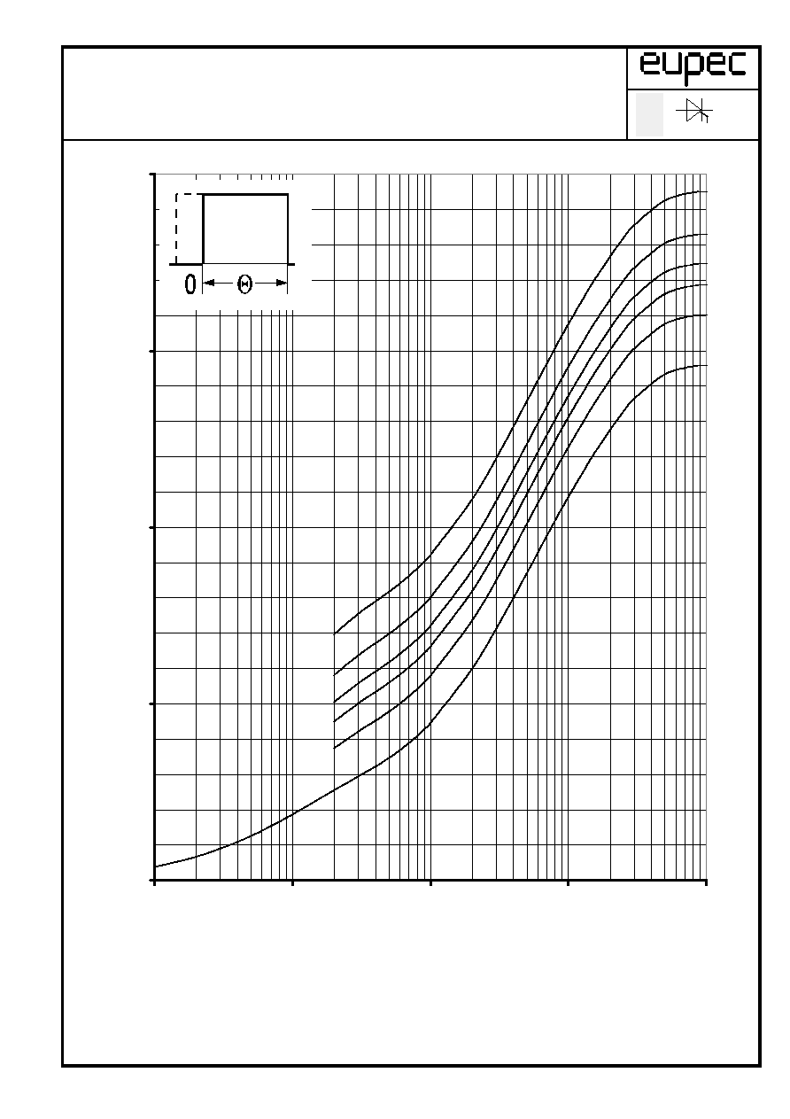
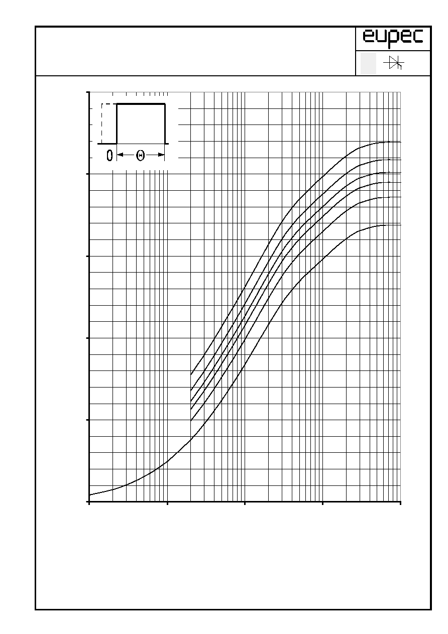
Hˆchstzul‰ssige Geh‰usetemperatur / Maximum allowable case temperature T
C
=f(I
TAVM
)
Beidseitige K¸hlung / two sided cooling
Parameter: Stromfluþwinkel
/ current conduction angle
Berechnungsgrundlage P
TAV
( Schaltverluste gesondert ber¸cksichtigen)
Calculation base P
TAV
(switching losses shold be considered separately)
SZ-M / 01.06.99 , K.-A. R¸ther
A 110/99
Z.Nr.: 8
Seite/page 11
20
40
60
80
100
120
140
0
1000
2000
3000
4000
5000
6000
I
TAVM
[A]
T
C
[∞C]
= 30∞
60∞
90∞
120∞
180∞
DC
Technische Information / Technical Information
Netz-Thyristor
Phase Control Thyristor
T 2476 N 22... 28
N
Hˆchstzul‰ssige K¸hlmitteltemperatur / Max. allowable cooling medium temperature T
A
= f (I
TAVM
)
Luftselbstk¸hlung / Natural air-cooling
Parameter: Stromfluþwinkel
/ current conduction angle
Berechnungsgrundlage P
TAV
( Schaltverluste gesondert ber¸cksichtigen)
Calculation base P
TAV
(switching losses shold be considered separately)
SZ-M / 01.06.99 , K.-A. R¸ther
A 110/99
Z.Nr.: 9
Seite/page 12
K¸hlkˆrper / Heatsink. K 0.48 F
20
40
60
80
100
120
140
0
100
200
300
400
500
I
TAVM
[A]
T
A
[∞C]
= 30∞
60∞
90∞
120∞
180∞
DC
Technische Information / Technical Information
Netz-Thyristor
Phase Control Thyristor
T 2476 N 22...28
N
Hˆchstzul‰ssige K¸hlmitteltemperatur / Max. allowable cooling medium temperature T
A
= f (I
TAVM
)
Verst‰rkte Luftk¸hlung / Forced air-cooling
Parameter: Stromfluþwinkel
/ current conduction angle
Berechnungsgrundlage P
TAV
( Schaltverluste gesondert ber¸cksichtigen)
Calculation base P
TAV
(switching losses shold be considered separately)
SZ-M / 01.06.99 , K.-A. R¸ther
A 110/99
Z.Nr.: 10
Seite/page 13
K¸hlkˆrper / Heatsink. K 0.48F, V
L
= 120 l/s
20
40
60
80
100
120
140
0
200
400
600
800
1000
1200
1400
1600
I
TAVM
[A]
T
A
[∞C]
= 30∞
60∞
90∞
120∞
180∞
DC
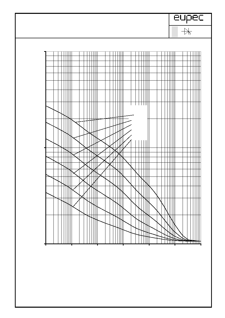
Technische Information / Technical Information
Netz-Thyristor
Phase Control Thyristor
T 2476 N 22... 28
N
Ðberstrom / Overload on-state current I
T(OV)
= f(t)
Luftselbstk¸hlung / Natural cooling K 0.48F
T
A
= 45∞C
Parameter: Vorlaststrom / pre-load current I
TAV(vor)
SZ-M / 01.06.99 , K.-A. R¸ther
A 110/99
Z. Nr.: 11
Seite/page 14
1.000
10.000
100.000
0,01
0,1
1
10
100
1000
10000
t [s]
I
T (OV)
[A]
I
TAV (vor)
=
0 A
180 A
260 A
300 A
320 A
330 A
Technische Information / Technical Information
Netz-Thyristor
Phase Control Thyristor
T 2476 N 22...28
N
Ðberstrom / Overload on-state current I
T(OV)
= f(t)
Verst‰rkte K¸hlung / Forced cooling K 0.48F
T
A
= 35∞C, V
L
= 120 l/s
Parameter: Vorlaststrom / pre-load current I
TAV(vor)
SZ-M / 01.06.99 , K.-A. R¸ther
A 110/99
Z. Nr.: 12
Seite/page 15
1.000
10.000
100.000
0,01
0,1
1
10
100
1000
t [s]
I
T (OV)
[A]
I
TAV (vor)
=
0 A
650 A
800 A
900 A
1000 A
1050 A
Technische Information / Technical Information
Netz-Thyristor
Phase Control Thyristor
T 2476 N 22...28
N
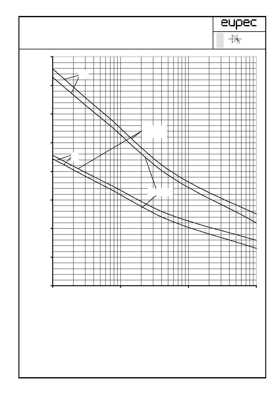
Grenzstrom / Max. overload on-state current I
T(OV)M
= f(t), v
RM
= 0,8 V
RRM
K¸hlkˆrper / Heatsink: K 0.48F
Belastung aus / Surge current occurs:
a - Leerlauf / No-load conditions
b - Betrieb mit Dauergrenzstrom / During operation at max. average on-state
current I
TAVM
SZ-M / 01.06.99 , K.-A. R¸ther
A 110/99
Z. Nr.: 13
Seite/page 16
0
5.000
10.000
15.000
20.000
25.000
30.000
35.000
40.000
0,01
0,1
1
10
t [s]
I
T(OV)M
[A]
a
b
T
A
= 35 ∞C
v
L
= 120l/s
T
A
= 45 ∞C
Technische Information / Technical Information
Netz-Thyristor
Phase Control Thyristor
T 2476 22...28
N
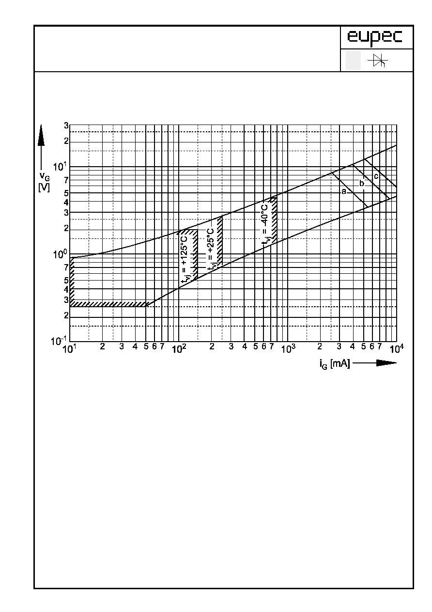
Steuercharakteristik v
G
= f (i
G
) mit Z¸ndbereichen f¸r V
D
= 6 V
Gate characteristic v
G
= f(i
G
) with triggering area for V
D
= 6 V
Hˆchstzul‰ssige Spitzensteuerverlustleistung / Maximum rated
peak gate power disspation PGM = f(tg):
a - 20W/10ms b - 40W/1ms c - 60/0,5ms
SZ-M / 01.06.99 , K.-A. R¸ther
A 110/99
Z.Nr.: 14
Seite/page 17
Technische Information / Technical Information
Netz-Thyristor
Phase Control Thyristor
T 2476 N 22...28
N
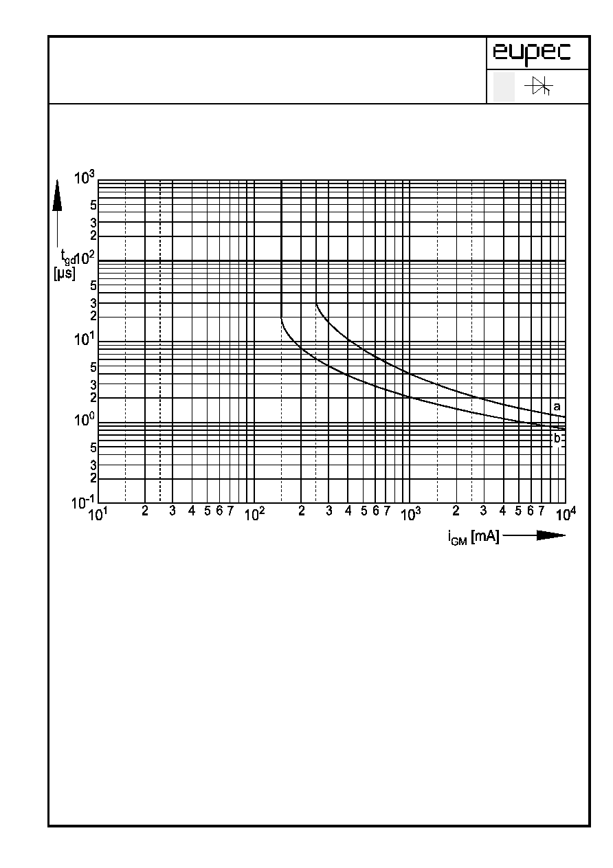
Z¸ndverzug / Gate controlled delay time t
gd
= f(i
G
)
T
vj
= 25∞C, di
G
/dt = i
GM
/ 1µs
a - maximaler Verlauf / limiting characteristic
b - typischer Verlauf / typical characteristic
SZ-M / 01.06.99 , K.-A. R¸ther
A 110/99
Z.Nr.: 15
Seite/page 18
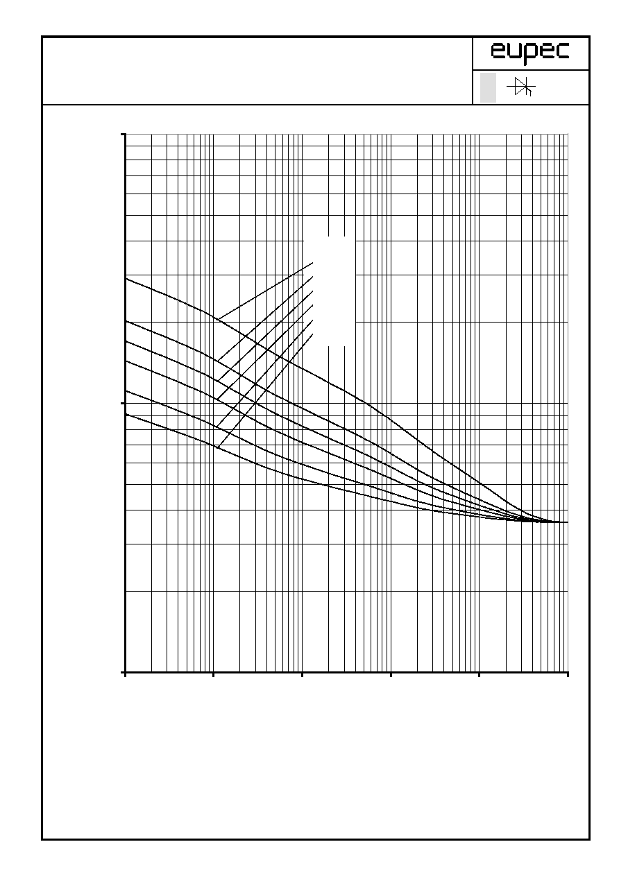
Technische Information / Technical Information
Netz-Thyristor
Phase Control Thyristor
T 2476 N 22...28
N
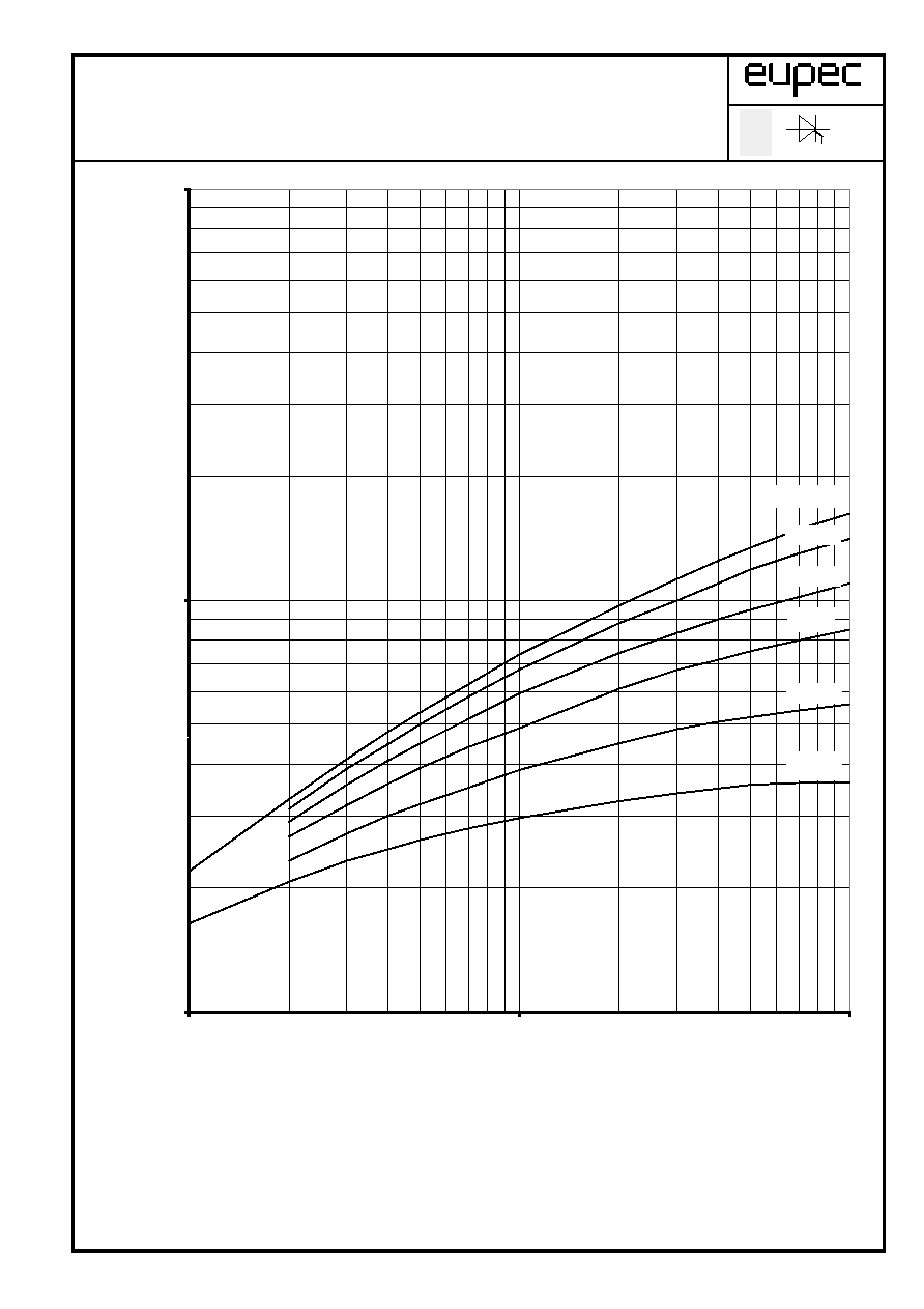
Sperrverzˆgerungsladung / Recovered charge Q
r
= f(-di/dt)
T
vj
= T
vj max
, v
R
<= 0,5 V
RRM
, v
RM
<= 0,8 V
RRM
Parameter: Durchlaþstrom / On-state current i
TM
SZ-M / 01.06.99 , K.-A. R¸ther
A 110/99
Z.Nr.: 16
Seite/page 19
1000
10000
100000
1
10
100
- di/dt [A/µs]
Q
r
[µAs]
i
TM
= 4000 A
100 A
200 A
500 A
1000 A
2000 A
50000
2
4
6
8
20
40
60
80
5000
Technische Information / Technical Information
Netz-Thyristor
Phase Control Thyristor
T 2476 N 22 ... 28
N
Transienter innerer W‰rmewiderstand / Transient thermal impedance Z
(th)JC
= f(t)
Beidseitige K¸hlung / Two-sided cooling
Parameter: Stromfluþwinkel
/ current conduction angle
SZ-M / 01.06.99 , K.-A. R¸ther
A 110/99
Z.Nr.:17
Seite/page 20
0,000
0,002
0,004
0,006
0,008
0,010
0,001
0,01
0,1
1
10
t [s]
Z
(th) JC
[∞C/W]
30∞
60∞
90∞
120∞
180∞
=
Technische Information / Technical Information
Netz-Thyristor
Phase Control Thyristor
T 2476N 22 ... 28
N
Transienter innerer W‰rmewiderstand / Transient thermal impedance Z
(th)JC
= f(t)
Beidseitige K¸hlung / Two-sided cooling
Parameter: Stromfluþwinkel
/ current conduction angle
SZ-M / 01.06.99 , K.-A. R¸ther
A 110/99
Z.Nr.: 18
Seite/page 21
0,000
0,002
0,004
0,006
0,008
0,010
0,012
0,001
0,01
0,1
1
10
t [s]
Z
(th) JC
[∞C/W]
DC
180∞
120∞
90∞
60∞
30∞
=
Technische Information / Technical Information
Netz-Thyristor
Phase Control Thyristor
T 2476 N 22 ... 28
N
Transienter innerer W‰rmewiderstand / Transient thermal impedance Z
(th)JC
= f(t)
Anodenseitige K¸hlung / Anode-sided sided cooling
Parameter: Stromfluþwinkel
/ current conduction angle
SZ-M / 01.06.99 , K.-A. R¸ther
A 110/99
Z.Nr.: 19
Seite/page 22
0,000
0,005
0,010
0,015
0,020
0,001
0,01
0,1
1
10
t [s]
Z
(th) JC
[∞C/W]
30∞
60∞
90∞
120∞
180∞
=
Technische Information / Technical Information
Netz-Thyristor
Phase Control Thyristor
T 2476 N 22 ... 28
N
Transienter innerer W‰rmewiderstand / Transient thermal impedance Z
(th)JC
= f(t)
Anodenseitige K¸hlung / Anode-sided cooling
Parameter: Stromfluþwinkel
/ current conduction angle
SZ-M / 01.06.99 , K.-A. R¸ther
A 110/99
Z.Nr.: 20
Seite/page 23
0,000
0,005
0,010
0,015
0,020
0,001
0,01
0,1
1
10
t [s]
Z
(th) JC
[∞C/W]
DC
180∞
120∞
90∞
60∞
30∞
=
Technische Information / Technical Information
Netz-Thyristor
Phase Control Thyristor
T 2476 N 22...28
N
Transienter innerer W‰rmewiderstand / Transient thermal impedance Z
(th)JC
= f(t)
Kathodenseitige K¸hlung / Cathde-sided cooling
Parameter: Stromfluþwinkel
/ current conduction angle
SZ-M / 01.06.99 , K.-A. R¸ther
A 110/99
Z.Nr.: 21
Seite/page 24
0,000
0,005
0,010
0,015
0,020
0,025
0,001
0,01
0,1
1
10
t [s]
Z
(th) JC
[∞C/W]
30∞
60∞
90∞
120∞
180∞
=
Technische Information / Technical Information
Netz-Thyristor
Phase Control Thyristor
T 2476 N 22 ... 28
N
Transienter innerer W‰rmewiderstand / Transient thermal impedance Z
(th)JC
= f(t)
Kathodenseitige K¸hlung / Cathode-sided cooling
Parameter: Stromfluþwinkel
/ current conduction angle
SZ-M / 01.06.99 , K.-A. R¸ther
A 110/99
Z.Nr.: 22
Seite/page 25
0,000
0,005
0,010
0,015
0,020
0,025
0,001
0,01
0,1
1
10
t [s]
Z
(th) JC
[∞C/W]
DC
180∞
120∞
90∞
60∞
30∞
=