 | –≠–ª–µ–∫—Ç—Ä–æ–Ω–Ω—ã–π –∫–æ–º–ø–æ–Ω–µ–Ω—Ç: ST16C1450 | –°–∫–∞—á–∞—Ç—å:  PDF PDF  ZIP ZIP |
Exar
Corporation 48720 Kato Road, Fremont CA, 94538
∑
(510) 668-7000
∑
FAX (510) 668-7017
∑
www.exar.com
·Á
·Á
·Á
·Á
ST16C1450/51
2.97V TO 5.5V UART
OCTOBER 2003
REV. 4.2.0
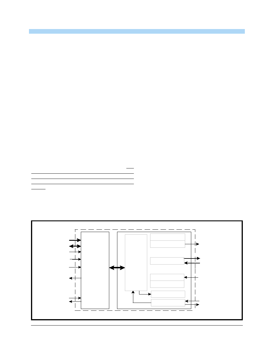
GENERAL DESCRIPTION
The ST16C1450, ST16C1451 series (here on
denoted as the 145X) is a universal asynchronous
receiver and transmitter (UART). The 145X is foot
print compatible to the SSI 73M1550 and SSI
73M2550 UART with one byte FIFO and higher
operating speed and lower access time. The 145X
provides enhanced UART functions with a modem
control interface, independent programmable baud
rate generators with clock rates to 1.5 Mbps. Onboard
status registers provide the user with error indications
and operational status. System interrupts and modem
control features may be tailored by external software
to meet specific user requirements. An internal loop-
back capability allows onboard diagnostics. The 145X
is available in a 28-pin PLCC/plastic-DIP, 48-pin
TQFP packages. The Baud rate generator can be
configured for either crystal or external clock input
with the exception of the 28 pin 1451 package. An
external clock must be provided for the 28 pin 1451
package. Each package type, with the exception of
the 28 pin 1450, provides a buffered reset output that
can be controlled through user software. The 145X is
fabricated in an advanced CMOS process to achieve
low drain power and high speed requirements. The
ST16C145X is not compatible with the industry
standard 16450 and will not work with the standard
serial port driver in MS Windows (see pages 15-16 for
details). For a MS Windows compatible UART, see
the ST16C450.
FEATURES
∑
Pin and functionally compatible to SSI 73M1550/
2550
∑
1 byte Transmit FIFO (THR)
∑
1 byte Receive FIFO with error tags (RHR)
∑
Four levels of prioritized interrupts
∑
Modem Control Signals (CTS#, RTS#, DSR#,
DTR#, RI#, CD#)
∑
Programmable character lengths (5, 6, 7, 8) with
even, odd or no parity
∑
Crystal or external clock input (except 28 pin
ST16C1451, external clock only)
∑
1.5 Mbps Transmit/Receive operation (24 MHz)
with programmable clock control
∑
Power Down Mode (50 uA at 3.3 V, 200 uA at 5 V)
∑
Software controllable reset output
∑
2.97 to 5.5 Volt operation
APPLICATIONS
∑
Battery Operated Electronics
∑
Internet Appliances
∑
Handheld Terminal
∑
Personal Digital Assistants
∑
Cellular Phones DataPort
F
IGURE
1. B
LOCK
D
IAGRAM
X T A L 1/C L K
X T A L 2
C ry stal O sc /B u ffe r
D T R # , R T S #
D SR # , C T S #,
C D #, R I#
D ata B u s
In te rfac e
T H R
B au d R ate G e n erato r
T ra n s m itter
U A R T
C o n fig u ra tio n
R eg s
IO R #
R H R
R ec e ive r
M o d e m C o n tro l S ig n a ls
T X
R X
IN T
A 2:A 0
D 7:D 0
C S#
IO W #
R ES E T
R ST

ST16C1450/51
·Á
·Á
·Á
·Á
2.97V TO 5.5V UART
REV. 4.2.0
2
F
IGURE
2. ST16C1450 P
INOUTS
28-PLCC PACKAGES
48-TQFP PACKAGE
48
47
46
45
44
43
42
41
40
39
38
37
1
2
3
4
5
6
7
8
9
10
11
12
36
35
34
33
32
31
30
29
28
27
26
25
13
14
15
16
17
18
19
20
21
22
23
24
N.C.
N.C.
D4
D5
D6
D7
RX
TX
CS#
N.C.
N.C.
N.C.
N.C.
N.C.
CTS#
RESET
DTR#
RTS#
A0
N.C.
A1
A2
N.C.
N.C.
N.C
.
D3
D2
D1
N.C
.
D0
N.C
.
VCC
CD
#
DSR
#
N.C
.
N.C
.
N.C
.
N.C
.
XTAL1
XTAL2
IOW
#
N.C
.
GN
D
IOR
#
RI#
RST
INT
N.C
.
ST16C1450CQ48
4
3
2
1
28
27
26
5
6
7
8
9
10
11
25
24
23
22
21
20
19
12
13
14
15
16
17
18
D4
D5
D6
D7
RX
TX
CS#
CTS#
RESET
DTR#
RTS#
A0
A1
A2
D3
D2
D1
D0
VCC
CD#
DSR#
XT
AL1
XT
AL2
IO
W
#
GN
D
IO
R
#
RI#
IN
T
ST16C1450CJ28
1
2
3
4
5
6
7
8
9
10
11
12
13
14
28
27
26
25
24
23
22
21
20
19
18
17
16
15
D0
D1
D2
D3
D4
D5
D6
D7
RX
TX
CS#
XTAL1
XTAL2
IOW#
VCC
CD#
DSR#
CTS#
RESET
DTR#
RTS#
A0
A1
A2
INT
RI#
IOR#
GND
S
T
16C145
0CP
2
8
28-PDIP PACKAGES
N
OTE
:
PINOUTS
NOT
TO
SCALE
.
ACTUAL
SIZE
OF
TQFP
PACKAGE
IS
SMALLER
THAN
PLCC
PACKAGE
.

·Á
·Á
·Á
·Á
ST16C1450/51
REV. 4.2.0
2.97V TO 5.5V UART
3
F
IGURE
3. ST16C1451 P
INOUTS
28-PLCC PACKAGES
48-TQFP PACKAGE
4
3
2
1
28
27
26
5
6
7
8
9
10
11
25
24
23
22
21
20
19
12
13
14
15
16
17
18
D4
D5
D6
D7
RX
TX
CS#
CTS#
RESET
DTR#
RTS#
A0
A1
A2
D3
D2
D1
D0
VC
C
CD
#
DS
R#
CLK
IO
W
#
GND
IO
R#
RI#
RST
INT
ST16C1451CJ28
1
2
3
4
5
6
7
8
9
10
11
12
13
14
28
27
26
25
24
23
22
21
20
19
18
17
16
15
D0
D1
D2
D3
D4
D5
D6
D7
RX
TX
CS#
CLK
IOW#
GND
VCC
CD#
DSR#
CTS#
RESET
DTR#
RTS#
A0
A1
A2
INT
RST
RI#
IOR#
ST
1
6
C145
1CP28
28-PDIP PACKAGES
N
OTE
:
PINOUTS
NOT
TO
SCALE
.
ACTUAL
SIZE
OF
TQFP
PACKAGE
IS
SMALLER
THAN
PLCC
PACKAGE
.
48
47
46
45
44
43
42
41
40
39
38
37
1
2
3
4
5
6
7
8
9
10
11
12
36
35
34
33
32
31
30
29
28
27
26
25
13
14
15
16
17
18
19
20
21
22
23
24
N.C.
N.C.
D4
D5
D6
D7
RX
TX
CS#
N.C.
N.C.
N.C.
N.C.
N.C.
CTS#
RESET
DTR#
RTS#
A0
N.C.
A1
A2
N.C.
N.C.
N.C
.
D3
D2
D1
N.C
.
D0
N.C
.
VCC
CD
#
DSR
#
N.C
.
N.C
.
N.C
.
N.C
.
XTAL1
XTAL2
IOW
#
N.C
.
GN
D
IOR
#
RI#
RST
INT
N.C
.
ST16C1451CQ48

ST16C1450/51
·Á
·Á
·Á
·Á
2.97V TO 5.5V UART
REV. 4.2.0
4
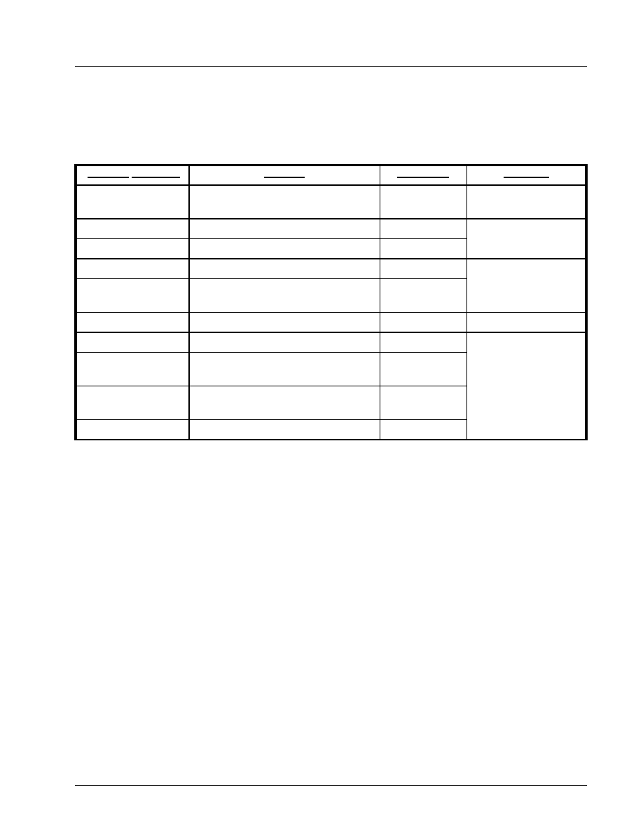
ORDERING INFORMATION
P
ART
N
UMBER
P
ACKAGE
O
PERATING
T
EMPERATURE
R
ANGE
D
EVICE
S
TATUS
ST16C1450CP28
28-Lead PDIP
0∞C to +70∞C
Discontinued. See the ST16C1450CQ48 for a replacement.
ST16C1450CJ28
28-Lead PLCC
0∞C to +70∞C
Active
ST16C1450CQ48
48-Lead TQFP
0∞C to +70∞C
Active
ST16C1451CP28
28-Lead PDIP
0∞C to +70∞C
Discontinued. See the ST16C1450CQ48 for a replacement.
ST16C1451CJ28
28-Lead PLCC
0∞C to +70∞C
Discontinued. See the ST16C1450CQ48 for a replacement.
ST16C1451CQ48
48-Lead TQFP
0∞C to +70∞C
Discontinued. See the ST16C1450CQ48 for a replacement.
ST16C1450IP28
28-Lead PDIP
-40∞C to +85∞C Discontinued. See the ST16C1450IQ48 for a replacement.
ST16C1450IJ28
28-Lead PLCC
-40∞C to +85∞C Active
ST16C1450IQ48
48-Lead TQFP
-40∞C to +85∞C Active
ST16C1451IP28
28-Lead PDIP
-40∞C to +85∞C Discontinued. See the ST16C1450IQ48 for a replacement.
ST16C1451IJ28
28-Lead PLCC
-40∞C to +85∞C Discontinued. See the ST16C1450IQ48 for a replacement.
ST16C1451IQ48
48-Lead TQFP
-40∞C to +85∞C Discontinued. See the ST16C1450IQ48 for a replacement.

·Á
·Á
·Á
·Á
ST16C1450/51
REV. 4.2.0
2.97V TO 5.5V UART
5
PIN DESCRIPTIONS
N
AME
28-P
IN
PDIP
(1450)
28-P
IN
PDIP
(1451)
28-P
IN
PLCC
(1450)
28-P
IN
PLCC
(1451)
48-P
IN
TQFP
(145X)
T
YPE
D
ESCRIPTION
DATA BUS INTERFACE
A0
A1
A2
21
20
19
21
20
19
21
20
19
21
20
19
30
28
27
I
Address data lines [2:0]. A2:A0 selects internal UART's
configuration registers.
D0
D1
D2
D3
D4
D5
D6
D7
1
2
3
4
5
6
7
8
1
2
3
4
5
6
7
8
1
2
3
4
5
6
7
8
1
2
3
4
5
6
7
8
43
45
46
47
3
4
5
6
I/O
Data bus lines [7:0] (bidirectional).
IOR#
16
15
16
15
20
I
Input/Output Read (active low). The falling edge instigates
an internal read cycle and retrieves the data byte from an
internal register pointed by the address lines [A2:A0], places
it on the data bus to allow the host processor to read it on
the leading edge.
IOW#
14
13
14
13
17
I
Input/Output Write (active low). The falling edge instigates
the internal write cycle and the rising edge transfers the
data byte on the data bus to an internal register pointed by
the address lines [A2:A0].
CS#
11
11
11
11
9
I
Chip Select input (active low). A logic 0 on this pin selects
the ST16C145X device.
INT
18
18
18
18
23
O
Interrupt Output (three-state, active high). INT output
defaults to three-state mode and becomes active high when
MCR bit-3 is set to a logic 1. INT output becomes a logic
high level when interrupts are enabled in the interrupt
enable register (IER), and whenever the transmitter,
receiver, line and/or modem status register has an active
condition.
MODEM OR SERIAL I/O INTERFACE
TX
10
10
10
10
8
O
Transmit Data. This output is associated with individual
serial transmit channel data from the 145X. The TX signal
will be a logic 1 during reset, idle (no data), or when the
transmitter is disabled. During the local loopback mode, the
TX output pin is disabled and TX data is internally con-
nected to the UART RX input.
RX
9
9
9
9
7
I
Receive Data. This input is associated with individual serial
channel data to the 145X. Normal received data input idles
at logic 1 condition. This input must be connected to its idle
logic state, logic 1, else the receiver may report "receive
break" and/or "error" condition(s).

ST16C1450/51
·Á
·Á
·Á
·Á
2.97V TO 5.5V UART
REV. 4.2.0
6
RTS#
22
22
22
22
31
O
Request to Send or general purpose output (active low). If
this pin is not needed for modem communication, then it can
be used as a general I/O. If it is not used, leave it uncon-
nected.
CTS#
25
25
25
25
34
I
Clear to Send or general purpose input (active low). If this
pin is not needed for modem communication, then it can be
used as a general I/O. If it is not used, connect it to VCC.
DTR#
23
23
23
23
32
O
Data Terminal Ready or general purpose output (active
low). If this pin is not needed for modem communication,
then it can be used as a general I/O. If it is not used, leave it
unconnected.
DSR#
26
26
26
26
39
I
Data Set Ready input or general purpose input (active low).
If this pin is not needed for modem communication, then it
can be used as a general I/O. If it is not used, connect it to
VCC.
CD#
27
27
27
27
40
I
Carrier Detect input or general purpose input (active low). If
this pin is not needed for modem communication, then it can
be used as a general I/O. If it is not used, connect it to VCC.
RI#
17
16
17
16
21
I
Ring Indicator input or general purpose input (active low). If
this pin is not needed for modem communication, then it can
be used as a general I/O. If it is not used, connect it to VCC.
ANCILLARY SIGNALS
CLK
-
12
-
12
-
I
External Clock Input. This function is associated with 28 pin
PDIP and 28 pin PLCC ST16C1451 packages only. An
external clock must be connected to this pin to clock the
baud rate generator and internal circuitry.
XTAL1
12
-
12
-
15
I
Crystal or external clock input. See
Figure 4
for typical
oscillator connections.
XTAL2
13
-
13
-
16
O
Crystal or buffered clock output. See
Figure 4
for typical
oscillator connections.
RESET
24
24
24
24
33
I
Reset Input (active high). When it is asserted, the UART
configuration registers are reset to default values, see
Table 6
.
RST
-
17
-
17
22
O
Reset Output (active high). This output is only available on
the ST16C1451. When IER bit-5 is a logic 0, RST will follow
the logical state of the RESET pin. When IER bit-5 is a logic
1, the user may send software (soft) resets via MCR bit-2.
Soft resets from MCR bit-2 are "ORed" with the state of the
RESET pin.
VCC
28
28
28
28
41
Pwr
Power supply input of 2.97 to 5.5V.
N
AME
28-P
IN
PDIP
(1450)
28-P
IN
PDIP
(1451)
28-P
IN
PLCC
(1450)
28-P
IN
PLCC
(1451)
48-P
IN
TQFP
(145X)
T
YPE
D
ESCRIPTION

·Á
·Á
·Á
·Á
ST16C1450/51
REV. 4.2.0
2.97V TO 5.5V UART
7
Pin type: I=Input, O=Output, I/O= Input/output, OD=Output Open Drain.
1.0
PRODUCT DESCRIPTION
The ST16C145X provides serial asynchronous receive data synchronization, parallel-to-serial and serial-to-
parallel data conversions for both the transmitter and receiver sections. These functions are necessary for
converting the serial data stream into parallel data that is required in digital data systems. Synchronization for
the serial data stream is accomplished by adding start and stops bits to the transmit data to form a data
character (character orientated protocol). Data integrity is ensured by attaching a parity bit to the data
character. The parity bit is checked by the receiver for any transmission bit errors. The 145X is capable of
operation up to 1.5 Mbps with a 24 MHz crystal or external clock input with a 16X sampling clock (at VCC =
5.0V). With a crystal of 14.7456 MHz and through a software option, the user can select data rates up to 921.6
Kbps.
2.0
FUNCTIONAL DESCRIPTIONS
2.1
Internal Registers
The 145X has a set of enhanced registers for controlling, monitoring and data loading and unloading. These
registers function as data holding registers (THR/RHR), interrupt status and control registers (ISR/IER), a FIFO
control register (FCR), receive line status and control registers (LSR/LCR), modem status and control registers
(MSR/MCR), programmable data rate (clock) divisor registers (DLL/DLM), and a user accessible scractchpad
register (SPR). All the register functions are discussed in full detail later in
"Section 3.0, UART INTERNAL
REGISTERS" on page 13
.
GND
15
14
15
14
19
Pwr
Power supply common ground.
N.C.
-
-
-
-
1, 2,
10-14,
18,
24-26,
29,
35-38,
42, 44,
48
-
Not connected.
N
AME
28-P
IN
PDIP
(1450)
28-P
IN
PDIP
(1451)
28-P
IN
PLCC
(1450)
28-P
IN
PLCC
(1451)
48-P
IN
TQFP
(145X)
T
YPE
D
ESCRIPTION

ST16C1450/51
·Á
·Á
·Á
·Á
2.97V TO 5.5V UART
REV. 4.2.0
8
2.2
Crystal Oscillator or External Clock
The 145X includes an on-chip oscillator (XTAL1 and XTAL2). The crystal oscillator provides the system clock to
the Baud Rate Generators (BRG) in the UART. XTAL1 is the input to the oscillator or external clock buffer input
with XTAL2 pin being the output. For programming details, see
"Section 2.3, Programmable Baud Rate
Generator" on page 8
.
The on-chip oscillator is designed to use an industry standard microprocessor crystal (parallel resonant,
fundamental frequency with 10-22 pF capacitance load, ESR of 20-120 ohms and 100ppm frequency
tolerance) connected externally between the XTAL1 and XTAL2 pins (see
Figure 4
). Alternatively, an external
clock can be connected to the XTAL1 pin to clock the internal baud rate generator for standard or custom rates.
Typical oscillator connections are shown in
Figure 4
. For further reading on oscillator circuit please see
application note DAN108 on EXAR's web site.
2.3
Programmable Baud Rate Generator
The UART has its own Baud Rate Generator (BRG). The BRG divides the input crystal or external clock by a
programmable divisor between 1 and (2
16
-1) to obtain a 16X sampling clock of the serial data rate. The
sampling clock is used by the transmitter for data bit shifting and
receiver for data sampling. The BRG divisor
(DLL and DLM registers) defaults to a random value upon power up or a reset. Therefore, the BRG must be
programmed during initialization to the operating data rate. Programming the Baud Rate Generator Registers
DLM and DLL provides the capability of selecting the operating data rate.
Table 1
shows the standard data
rates available with a 14.7456 MHz crystal or external clock at 16X clock rate. When using a non-standard data
rate crystal or external clock, the divisor value can be calculated for DLL/DLM with the following equation.
F
IGURE
4. T
YPICAL
OSCILLATOR
CONNECTIONS
divisor (decimal) = (XTAL1 clock frequency) / (serial data rate x 16)
C1
22-47pF
C2
22-47pF
Y1
1.8432 MHz
to
24 MHz
R1
0-120
(Optional)
R2
500K - 1M
XTAL1
XTAL2

·Á
·Á
·Á
·Á
ST16C1450/51
REV. 4.2.0
2.97V TO 5.5V UART
9
2.4
Transmitter
The transmitter section comprises of an 8-bit Transmit Shift Register (TSR) and 16 bytes of FIFO which
includes a byte-wide Transmit Holding Register (THR). TSR shifts out every data bit with the 16X internal clock.
A bit time is 16 clock periods. The transmitter sends the start-bit followed by the number of data bits, inserts the
proper parity-bit if enabled, and adds the stop-bit(s). The status of the FIFO and TSR are reported in the Line
Status Register (LSR bit-5 and bit-6).
2.4.1
Transmit Holding Register (THR) - Write Only
The transmit holding register is an 8-bit register providing a data interface to the host processor. The host
writes transmit data byte to the THR to be converted into a serial data stream including start-bit, data bits,
parity-bit and stop-bit(s). The least-significant-bit (Bit-0) becomes first data bit to go out. The THR is the input
register to the transmit FIFO of 16 bytes when FIFO operation is enabled by FCR bit-0. Every time a write
operation is made to the THR, the FIFO data pointer is automatically bumped to the next sequential data
location.
2.4.2
Transmitter Operation
The host loads transmit data to THR one character at a time. The THR empty flag (LSR bit-5) is set when the
data byte is transferred to TSR. THR flag can generate a transmit empty interrupt (ISR bit-1) when it is enabled
by IER bit-1. The TSR flag (LSR bit-6) is set when TSR becomes completely empty.
T
ABLE
1: T
YPICAL
DATA
RATES
WITH
A
14.7456 MH
Z
CRYSTAL
OR
EXTERNAL
CLOCK
O
UTPUT
Data Rate
D
IVISOR
FOR
16x
Clock (Decimal)
D
IVISOR
FOR
16x
Clock (HEX)
DLM P
ROGRAM
V
ALUE
(HEX)
DLL P
ROGRAM
V
ALUE
(HEX)
D
ATA
R
ATE
E
RROR
(%)
400
2304
900
09
00
0
2400
384
180
01
80
0
4800
192
C0
00
C0
0
9600
96
60
00
60
0
19.2k
48
30
00
30
0
38.4k
24
18
00
18
0
76.8k
12
0C
00
0C
0
153.6k
6
06
00
06
0
230.4k
4
04
00
04
0
460.8k
2
02
00
02
0
921.6k
1
01
00
01
0

ST16C1450/51
·Á
·Á
·Á
·Á
2.97V TO 5.5V UART
REV. 4.2.0
10
2.5
Receiver
The receiver section contains an 8-bit Receive Shift Register (RSR) and a byte-wide Receive Holding Register
(RHR). The RSR uses the 16X clock for timing. It verifies and validates every bit on the incoming character in
the middle of each data bit. On the falling edge of a start or false start bit, an internal receiver counter starts
counting at the 16X clock rate. After 8 clocks the start bit period should be at the center of the start bit. At this
time the start bit is sampled and if it is still a logic 0 it is validated. Evaluating the start bit in this manner
prevents the receiver from assembling a false character. The rest of the data bits and stop bits are sampled and
validated in this same manner to prevent false framing. If there were any error(s), they are reported in the LSR
register bits 2-4. Upon unloading the receive data byte from RHR, the error tags are immediately updated to
reflect the status of the data byte in RHR register. RHR can generate a receive data ready interrupt upon
receiving a characterThe RHR interrupt is enabled by IER bit-0.
2.5.1
Receive Holding Register (RHR) - Read-Only
The Receive Holding Register is an 8-bit register that holds a receive data byte from the Receive Shift Register.
It provides the receive data interface to the host processor. When there is data in the RHR register, the 3 error
tags in LSR register (bits 2-4) indicates if there are any errors associated with that byte.
F
IGURE
5. T
RANSMITTER
O
PERATION
Transmit
Holding
Register
(THR)
Transmit Shift Register (TSR)
Data
Byte
L
S
B
M
S
B
THR Interrupt (ISR bit-1)
Enabled by IER bit-1
TXNOFIFO1
16X Clock

·Á
·Á
·Á
·Á
ST16C1450/51
REV. 4.2.0
2.97V TO 5.5V UART
11
2.6
Special (Enhanced Feature) Mode
The 145X supports the standard features of the ST16C450. In addition the 145X supports some enhanced
features not available for the ST16C450. These features are enabled by IER bit-5 and include a software
controllable (SOFT) reset, power down feature and FIFO monitoring bits.
2.6.1
Soft Reset
Soft resets are useful when the user desires the capability of resetting an externally connected device only.
MCR bit-2 can be used to initiate a SOFT reset at the RST output pin. This does not reset the 145X (only the
RESET input pin can reset the 145X). Soft resets from MCR bit-2 are "ORed" with the RESET input pin.
Therefore both reset types will be seen at the RST output pin.
2.6.2
Power Down Mode
The power down feature (controlled by MCR bit-7) provides the user with the capability to conserve power
when the package is not in actual use without destroying internal register configuration data. This allows quick
turnarounds from power down to normal operation.
2.7
Internal Loopback
The 145X UART provides an internal loopback capability for system diagnostic purposes. The internal
loopback mode
is enabled by setting MCR register bit-4 to logic 1. All regular UART functions operate normally.
Figure 7
shows how the modem port signals are re-configured. Transmit data from the transmit shift register
output is internally routed to the receive shift register input allowing the system to receive the same data that it
was sending. The TX pin is held at logic 1 or mark condition while RTS# and DTR# are de-asserted, and
CTS#, DSR# CD# and RI# inputs are ignored. Caution: the RX input must be held to a logic 1 during loopback
test else upon exiting the loopback test the UART may detect and report a false "break" signal.
F
IGURE
6. R
ECEIVER
O
PERATION
IN
NON
-FIFO M
ODE
Receive Data Shift
Register (RSR)
Receive
Data Byte
and Errors
RHR Interrupt (ISR bit-2)
Receive Data
Holding Register
(RHR)
RXFIFO1
16X Clock
Receive Data Characters
Data Bit
Validation
Error
Tags in
LSR bits
4:2

ST16C1450/51
·Á
·Á
·Á
·Á
2.97V TO 5.5V UART
REV. 4.2.0
12
F
IGURE
7. I
NTERNAL
L
OOPBACK
TX
RX
Mo
dem
/
G
e
n
e
r
a
l
P
u
r
p
ose
C
o
n
t
r
o
l
Logi
c
Inte
r
n
a
l D
a
ta
B
u
s L
ines
and
Co
ntr
ol Sign
als
RTS#
MCR bit-4=1
VCC
VCC
Transmit Shift Register
Receive Shift Register
CTS#
DTR#
DSR#
RI#
CD#
OP1#
OP2#
RTS#
CTS#
DTR#
DSR#
RI#
CD#
VCC
·Á
·Á
·Á
·Á
ST16C1450/51
REV. 4.2.0
2.97V TO 5.5V UART
13
3.0
UART INTERNAL REGISTERS
The 145X has a set of configuration registers selected by address lines A0, A1 and A2. The 16C450
compatible registers can be accessed when LCR[7] = 0 and the baud rate generator divisor registers can be
accessed when LCR[7] = 1. The complete register set is shown on
Table 2
and
Table 3
.
T
ABLE
2: ST16C145X UART INTERNAL REGISTERS
A2,A1,A0 A
DDRESSES
R
EGISTER
R
EAD
/W
RITE
C
OMMENTS
0 0 0
RHR - Receive Holding Register
THR - Transmit Holding Register
Read-only
Write-only
LCR[7] = 0
0 0 0
DLL - Div Latch Low Byte
Read/Write
LCR[7] = 1
0 0 1
DLM - Div Latch High Byte
Read/Write
0 0 1
IER - Interrupt Enable Register
Read/Write
LCR[7] = 0
0 1 0
ISR - Interrupt Status Register
Reserved
Read-only
Write-only
0 1 1
LCR - Line Control Register
Read/Write
1 0 0
MCR - Modem Control Register
Read/Write
LCR[7] = 0
1 0 1
LSR - Line Status Register
Reserved
Read-only
Write-only
1 1 0
MSR - Modem Status Register
Reserved
Read-only
Write-only
1 1 1
SPR - Scratch Pad Register
Read/Write

ST16C1450/51
·Á
·Á
·Á
·Á
2.97V TO 5.5V UART
REV. 4.2.0
14
.
T
ABLE
3: INTERNAL REGISTERS DESCRIPTION.
S
HADED
BITS
ARE
ENABLED
WHEN
EFR B
IT
-4=1
A
DDRESS
A2-A0
R
EG
N
AME
R
EAD
/
W
RITE
B
IT
-7
B
IT
-6
B
IT
-5
B
IT
-4
B
IT
-3
B
IT
-2
B
IT
-1
B
IT
-0
C
OMMENT
16C550 Compatible Registers
0 0 0
RHR
RD
Bit-7
Bit-6
Bit-5
Bit-4
Bit-3
Bit-2
Bit-1
Bit-0
LCR[7] = 0
0 0 0
THR
WR
Bit-7
Bit-6
Bit-5
Bit-4
Bit-3
Bit-2
Bit-1
Bit-0
0 0 1
IER
RD/WR
0
0
Special
Mode
Enable
(Enable
MCR bits
7, 2)
0
Modem
Status
Int.
Enable
RX Line
Status
Int.
Enable
TX
Empty
Int.
Enable
RX
Data
Int.
Enable
0 1 0
ISR
RD
0
0
0
0
INT
Source
Bit-3
INT
Source
Bit-2
INT
Source
Bit-1
INT
Source
Bit-0
0 1 1
LCR
RD/WR
Divisor
Enable
Set TX
Break
Set
Parity
Even
Parity
Parity
Enable
Stop
Bits
Word
Length
Bit-1
Word
Length
Bit-0
1 0 0
MCR
RD/WR
0/
0
0
Internal
Loop-
back
Enable
(OP2#)/
INT
Output
Enable
(OP1#)/
RTS#
Output
Control
DTR#
Output
Control
LCR[7] = 0
Power
Down
Mode
SOFT
Reset
1 0 1
LSR
RD
0
THR &
TSR
Empty
THR
Empty
RX
Break
RX
Framing
Error
RX
Parity
Error
RX
Over-
run
Error
RX
Data
Ready
1 1 0
MSR
RD
CD#
Input
RI#
Input
DSR#
Input
CTS#
Input
Delta
CD#
Delta
RI#
Delta
DSR#
Delta
CTS#
1 1 1
SPR
RD/WR
Bit-7
Bit-6
Bit-5
Bit-4
Bit-3
Bit-2
Bit-1
Bit-0
Baud Rate Generator Divisor
0 0 0
DLL
RD/WR
Bit-7
Bit-6
Bit-5
Bit-4
Bit-3
Bit-2
Bit-1
Bit-0
LCR[7] = 1
0 0 1
DLM
RD/WR
Bit-7
Bit-6
Bit-5
Bit-4
Bit-3
Bit-2
Bit-1
Bit-0

·Á
·Á
·Á
·Á
ST16C1450/51
REV. 4.2.0
2.97V TO 5.5V UART
15
4.0
INTERNAL REGISTER DESCRIPTIONS
4.1
Receive Holding Register (RHR) - Read- Only
See "Receiver" on page 10.
4.2
Transmit Holding Register (THR) - Write-Only
See "Transmitter" on page 9.
4.3
Interrupt Enable Register (IER) - Read/Write
The Interrupt Enable Register (IER) masks the interrupts from receive data ready, transmit empty, line status
and modem status registers. These interrupts are reported in the Interrupt Status Register (ISR).
IER[0]: RHR Interrupt Enable
The receive data ready interrupt will be issued when RHR has a data character.
∑
Logic 0 = Disable the receive data ready interrupt (default).
∑
Logic 1 = Enable the receiver data ready interrupt.
IER[1]: THR Interrupt Enable
This bit enables the Transmit Ready interrupt which is issued whenever the THR is empty. If the THR is empty
when this bit is enabled, an interrupt will be generated. Note that this interrupt does not behave in the same
manner as the industry standard 16C550.
See "Interrupt Clearing:" on page 16.
∑
Logic 0 = Disable Transmit Ready interrupt (default).
∑
Logic 1 = Enable Transmit Ready interrupt.
IER[2]: Receive Line Status Interrupt Enable
If any of the LSR register bits 1, 2, 3 or 4 is a logic 1, it will generate an interrupt to inform the host controller
about the error status of the current data byte in the RHR.
∑
Logic 0 = Disable the receiver line status interrupt (default).
∑
Logic 1 = Enable the receiver line status interrupt.
IER[3]: Modem Status Interrupt Enable
∑
Logic 0 = Disable the modem status register interrupt (default).
∑
Logic 1 = Enable the modem status register interrupt.
IER[4]: Reserved
IER[5]: Special Mode Enable
∑
Logic 0 = Disable special mode functions (default).
∑
Logic 1 = Enable special mode functions in addition to basic ST16C1450 functions. Enables ISR bits 4-5
(TXRDY/RXRDY), MCR bit-2 (soft reset) and MCR bit-7 (power down) functions.
IER[7:6]: Reserved
4.4
Interrupt Status Register (ISR) - Read-Only
The UART provides multiple levels of prioritized interrupts to minimize external software interaction. The
Interrupt Status Register (ISR) provides the user with six interrupt status bits. Performing a read cycle on the
ISR will give the user the current highest pending interrupt level to be serviced, others are queued up to be
serviced next. No other interrupts are acknowledged until the pending interrupt is serviced. The Interrupt
Source Table,
Table 4
, shows the data values (bits 0-3) for the interrupt priority levels and the interrupt sources
associated with each of these interrupt levels.

ST16C1450/51
·Á
·Á
·Á
·Á
2.97V TO 5.5V UART
REV. 4.2.0
16
4.4.1
Interrupt Generation:
∑
LSR is by any of the LSR bits 1, 2, 3 and 4.
∑
RXRDY is by received data in RHR.
∑
TXRDY is by THR empty.
∑
MSR is by any of the MSR bits 0, 1, 2 and 3.
4.4.2
Interrupt Clearing:
∑
LSR interrupt is cleared by a read to the LSR register (but flags and tags not cleared until character(s) that
generated the interrupt(s) has been emptied or cleared from RHR).
∑
RXRDY interrupt is cleared by reading RHR.
∑
TXRDY interrupt is cleared by a read to the ISR register AND disabling the TXRDY interrupt (set IER bit-1 =
0), or by loading data into the TX FIFO.
∑
MSR interrupt is cleared by a read to the MSR register.
]
ISR[0]: Interrupt Status
∑
Logic 0 = An interrupt is pending and the ISR contents may be used as a pointer to the appropriate interrupt
service routine.
∑
Logic 1 = No interrupt pending (default condition).
ISR[3:1]: Interrupt Status
These bits indicate the source for a pending interrupt at interrupt priority levels (See Interrupt Source
Table 4
).
ISR[7:4]: Reserved
4.5
Line Control Register (LCR) - Read/Write
The Line Control Register is used to specify the asynchronous data communication format. The word or
character length, the number of stop bits, and the parity are selected by writing the appropriate bits in this
register.
T
ABLE
4: I
NTERRUPT
S
OURCE
AND
P
RIORITY
L
EVEL
P
RIORITY
L
EVEL
ISR R
EGISTER
S
TATUS
B
ITS
S
OURCE
OF
INTERRUPT
B
IT
-3
B
IT
-2
B
IT
-1
B
IT
-0
1
0
1
1
0
LSR (Receiver Line Status Register)
2
0
1
0
0
RXRDY (Received Data Ready)
3
0
0
1
0
TXRDY (Transmit Ready)
4
0
0
0
0
MSR (Modem Status Register)
-
0
0
0
1
None (default)

·Á
·Á
·Á
·Á
ST16C1450/51
REV. 4.2.0
2.97V TO 5.5V UART
17
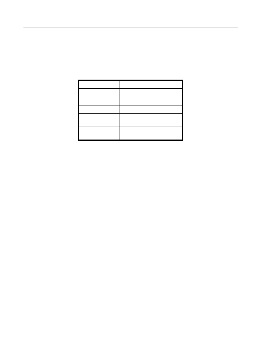
LCR[1:0]: TX and RX Word Length Select
These two bits specify the word length to be transmitted or received.
LCR[2]: TX and RX Stop-bit Length Select
The length of stop bit is specified by this bit in conjunction with the programmed word length.
LCR[3]: TX and RX Parity Select
Parity or no parity can be selected via this bit. The parity bit is a simple way used in communications for data
integrity check. See
Table 5
for parity selection summary below.
∑
Logic 0 = No parity.
∑
Logic 1 = A parity bit is generated during the transmission while the receiver checks for parity error of the
data character received.
LCR[4]: TX and RX Parity Select
If the parity bit is enabled with LCR bit-3 set to a logic 1, LCR BIT-4 selects the even or odd parity format.
∑
Logic 0 = ODD Parity is generated by forcing an odd number of logic 1's in the transmitted character. The
receiver must be programmed to check the same format (default).
∑
Logic 1 = EVEN Parity is generated by forcing an even number of logic 1's in the transmitted character. The
receiver must be programmed to check the same format.
BIT-1
BIT-0
W
ORD
LENGTH
0
0
5 (default)
0
1
6
1
0
7
1
1
8
BIT-2
W
ORD
LENGTH
S
TOP
BIT
LENGTH
(B
IT
TIME
(
S
))
0
5,6,7,8
1 (default)
1
5
1-1/2
1
6,7,8
2
ST16C1450/51
·Á
·Á
·Á
·Á
2.97V TO 5.5V UART
REV. 4.2.0
18
LCR[5]: TX and RX Parity Select
If the parity bit is enabled, LCR BIT-5 selects the forced parity format.
∑
LCR[5] = logic 0, parity is not forced (default).
∑
LCR[5] = logic 1 and LCR[4] = logic 0, parity bit is forced to a logical 1 for the transmit and receive data.
∑
LCR[5] = logic 1 and LCR[4] = logic 1, parity bit is forced to a logical 0 for the transmit and receive data.
LCR[6]: Transmit Break Enable
When enabled, the Break control bit causes a break condition to be transmitted (the TX output is forced to a
"space', logic 0, state). This condition remains, until disabled by setting LCR bit-6 to a logic 0.
∑
Logic 0 = No TX break condition (default).
∑
Logic 1 = Forces the transmitter output (TX) to a "space", logic 0, for alerting the remote receiver of a line
break condition.
LCR[7]: Baud Rate Divisors Enable
Baud rate generator divisor (DLL/DLM) enable.
∑
Logic 0 = Data registers are selected (default).
∑
Logic 1 = Divisor latch registers are selected.
4.6
Modem Control Register (MCR) or General Purpose Outputs Control - Read/Write
The MCR register is used for controlling the serial/modem interface signals or general purpose inputs/outputs.
MCR[0]: DTR# Output
The DTR# pin is a modem control output. If the modem interface is not used, this output may be used as a
general purpose output.
∑
Logic 0 = Force DTR# output to a logic 1 (default).
∑
Logic 1 = Force DTR# output to a logic 0.
MCR[1]: RTS# Output
The RTS# pin is a modem control output. If the modem interface is not used, this output may be used as a
general purpose output.
∑
Logic 0 = Force RTS# output to a logic 1 (default).
∑
Logic 1 = Force RTS# output to a logic 0.
T
ABLE
5: P
ARITY
SELECTION
LCR B
IT
-5 LCR B
IT
-4 LCR B
IT
-3
P
ARITY
SELECTION
X
X
0
No parity
0
0
1
Odd parity
0
1
1
Even parity
1
0
1
Force parity to mark,
"1"
1
1
1
Forced parity to
space, "0"

·Á
·Á
·Á
·Á
ST16C1450/51
REV. 4.2.0
2.97V TO 5.5V UART
19
MCR[2]: OP1# Output/Soft Reset
OP1# is not available as an output pin on the 145X. But it is available for use during Internal Loopback Mode.
In the Loopback Mode, this bit is used to write the state of the modem RI# interface signal.
∑
Logic 0 = OP1# output (RI# input) is at logic 1 (default).
∑
Logic 1 = OP1# output (RI# input) is at logic 0.
In normal operation, this bit is associated with the RST (buffered reset) output pin. The logical state of the RST
pin will follow exactly the logical state of the RESET pin. When IER bit-5 = 1, soft resets from MCR bit-2 are
ORed with the state of the RESET input pin. Therefore both reset types will be seen at the RST pin. Note that
asserting MCR bit-2 does not reset the 145X.
∑
Logic 0 = The RST output pin is a logic 0 (default).
∑
Logic 1 = The RST output pin is a logic 1.
MCR[3]: OP2# or INT Output Enable
When not in Internal Loopback Mode:
∑
Logic 0 = INT output is three-state (default).
∑
Logic 1 = INT output is active high.
OP2# is not available as an output pin on the 145X. But it is available for use during Internal Loopback Mode.
In the Loopback Mode, this bit is used to write the state of the modem CD# interface signal.
∑
Logic 0 = OP2# output (CD# input) is a logic 1 (default).
∑
Logic 1 = OP2# output (CD# input) is a logic 0.
MCR[4]: Internal Loopback Enable
∑
Logic 0 = Disable loopback mode (default).
∑
Logic 1 = Enable local loopback mode, see loopback section and
Figure 7
.
MCR[6:5]: Reserved
MCR[7]: Power Down Enable
This bit can only be accessed when IER bit-5 = 1.
∑
Logic 0 = Normal mode (default).
∑
Logic 1 = Power down mode.
See "Power Down Mode" on page 11.
4.7
Line Status Register (LSR) - Read Only
This register provides the status of data transfers between the UART and the host. If IER bit-2 is set to a logic
1, an LSR interrupt will be generated when the character that is in the RHR has an error (parity, framing,
overrun, break).
LSR[0]: Receive Data Ready Indicator
∑
Logic 0 = No data in receive holding register (default).
∑
Logic 1 = Data has been received and is saved in the receive holding register.
LSR[1]: Receiver Overrun Error Flag
∑
Logic 0 = No overrun error (default).
∑
Logic 1 = Overrun error. A data overrun error condition occurred in the receive shift register. This happens
when additional data arrives while there is data in the RHR. In this case the previous data in the receive shift
register is overwritten. Note that under this condition the data byte in the receive shift register is not
transferred into the RHR, therefore the data in the RHR is not corrupted by the error.

ST16C1450/51
·Á
·Á
·Á
·Á
2.97V TO 5.5V UART
REV. 4.2.0
20
LSR[2]: Receive Data Parity Error Tag
∑
Logic 0 = No parity error (default).
∑
Logic 1 = Parity error. The received character in RHR does not have correct parity information and is suspect.
This error is associated with the character available for reading in RHR.
LSR[3]: Receive Data Framing Error Tag
∑
Logic 0 = No framing error (default).
∑
Logic 1 = Framing error. The received character did not have a valid stop bit(s). This error is associated with
the character available for reading in RHR.
LSR[4]: Receive Break Error Tag
∑
Logic 0 = No break condition (default).
∑
Logic 1 = The receiver received a break signal (RX was a logic 0 for at least one character frame time).
LSR[5]: Transmit Holding Register Empty Flag
This bit is the Transmit Holding Register Empty indicator. The THR bit is set to a logic 1 when the data byte is
transferred from the transmit holding register to the transmit shift register. The bit is reset to logic 0 concurrently
with the data loading to the transmit holding register by the host.
LSR[6]: THR and TSR Empty Flag
This bit is set to a logic 1 whenever the transmitter goes idle. It is set to logic 0 whenever either the THR or TSR
contains a data character.
LSR[7]: Reserved
4.8
Modem Status Register (MSR) - Read Only
This register provides the current state of the modem interface input signals. Lower four bits of this register are
used to indicate the changed information. These bits are set to a logic 1 whenever a signal from the modem
changes state. These bits may be used for general purpose inputs when they are not used with modem
signals.
MSR[0]: Delta CTS# Input Flag
∑
Logic 0 = No change on CTS# input (default).
∑
Logic 1 = The CTS# input has changed state since the last time it was monitored. A modem status interrupt
will be generated if MSR interrupt is enabled (IER bit-3).
MSR[1]: Delta DSR# Input Flag
∑
Logic 0 = No change on DSR# input (default).
∑
Logic 1 = The DSR# input has changed state since the last time it was monitored. A modem status interrupt
will be generated if MSR interrupt is enabled (IER bit-3).
MSR[2]: Delta RI# Input Flag
∑
Logic 0 = No change on RI# input (default).
∑
Logic 1 = The RI# input has changed from a logic 0 to a logic 1, ending of the ringing signal. A modem status
interrupt will be generated if MSR interrupt is enabled (IER bit-3).
MSR[3]: Delta CD# Input Flag
∑
Logic 0 = No change on CD# input (default).
∑
Logic 1 = Indicates that the CD# input has changed state since the last time it was monitored. A modem
status interrupt will be generated if MSR interrupt is enabled (IER bit-3).
MSR[4]: CTS Input Status

·Á
·Á
·Á
·Á
ST16C1450/51
REV. 4.2.0
2.97V TO 5.5V UART
21
CTS#
(active high, logical 1). Normally this bit is the compliment of the CTS# input. In the loopback mode, this
bit is equivalent to bit-1 in the MCR register. The CTS# input may be used as a general purpose input when the
modem interface is not used.
MSR[5]: DSR Input Status
DSR#
(active high, logical 1). Normally this bit is the compliment of the DSR# input. In the loopback mode, this
bit is equivalent to bit-0 in the MCR register. The DSR# input may be used as a general purpose input when the
modem interface is not used.
MSR[6]: RI Input Status
RI# (active high, logical 1). Normally this bit is the compliment of the RI# input. In the loopback mode this bit is
equivalent to bit-2 in the MCR register. The RI# input may be used as a general purpose input when the
modem interface is not used.
MSR[7]: CD Input Status
CD# (active high, logical 1). Normally this bit is the compliment of the CD# input. In the loopback mode this bit
is equivalent to bit-3 in the MCR register. The CD# input may be used as a general purpose input when the
modem interface is not used.
4.9
Scratch Pad Register (SPR) - Read/Write
This is a 8-bit general purpose register for the user to store temporary data. The content of this register is
preserved during sleep mode but becomes 0xFF (default) after a reset or a power off-on cycle.
T
ABLE
6: UART RESET CONDITIONS
REGISTERS
RESET STATE
DLL
Bits 7-0 = 0xXX
DLM
Bits 7-0 = 0xXX
RHR
Bits 7-0 = 0xXX
THR
Bits 7-0 = 0xXX
IER
Bits 7-0 = 0x00
ISR
Bits 7-0 = 0x01
LCR
Bits 7-0 = 0x00
MCR
Bits 7-0 = 0x00
LSR
Bits 7-0 = 0x60
MSR
Bits 3-0 = Logic 0
Bits 7-4 = Logic levels of the inputs inverted
SPR
Bits 7-0 = 0xFF
I/O SIGNALS
RESET STATE
TX
Logic 1
RTS#
Logic 1
DTR#
Logic 1
RST
Logic 1
INT
Three-State Condition

ST16C1450/51
·Á
·Á
·Á
·Á
2.97V TO 5.5V UART
REV. 4.2.0
22
Test 1: The following inputs should remain steady at VCC or GND state to minimize Power Down current: A0-A2, D0-D7,
IOR#, IOW#, CS# and modem inputs. Also, RX input must idle at logic 1 state while in Power Down mode.
ABSOLUTE MAXIMUM RATINGS
Power Supply Range
7 Volts
Voltage at Any Pin
GND-0.3 V to 7 V
Operating Temperature
-40
o
to +85
o
C
Storage Temperature
-65
o
to +150
o
C
Package Dissipation
500 mW
TYPICAL PACKAGE THERMAL RESISTANCE DATA (
MARGIN
OF
ERROR
: ± 15%)
Thermal Resistance (48-TQFP)
theta-ja = 59
o
C/W, theta-jc = 16
o
C/W
Thermal Resistance (28-PDIP)
theta-ja = 57
o
C/W, theta-jc = 23
o
C/W
Thermal Resistance (28-PLCC)
theta-ja = 55
o
C/W, theta-jc = 28
o
C/W
ELECTRICAL CHARACTERISTICS
DC ELECTRICAL CHARACTERISTICS
U
NLESS
OTHERWISE
NOTED
: TA=0
O
TO
70
O
C (-40
O
TO
+85
O
C
FOR
INDUSTRIAL
GRADE
PACKAGE
), V
CC
IS
2.97V
TO
5.5V
S
YMBOL
P
ARAMETER
L
IMITS
3.3V
M
IN
M
AX
L
IMITS
5.0V
M
IN
M
AX
U
NITS
C
ONDITIONS
V
ILCK
Clock Input Low Level
-0.3
0.6
-0.5
0.6
V
V
IHCK
Clock Input High Level
2.4
VCC
3.0
VCC
V
V
IL
Input Low Voltage
-0.3
0.8
-0.5
0.8
V
V
IH
Input High Voltage
2.0
VCC
2.2
VCC
V
V
OL
Output Low Voltage
0.4
V
I
OL
= 6 mA
V
OL
Output Low Voltage
0.4
V
I
OL
= 4 mA
V
OH
Output High Voltage
2.4
V
I
OH
= -6 mA
V
OH
Output High Voltage
2.0
V
I
OH
= -1 mA
I
IL
Input Low Leakage Current
±10
±10
uA
I
IH
Input High Leakage Current
±10
±10
uA
C
IN
Input Pin Capacitance
5
5
pF
I
CC
Power Supply Current
1.3
3
mA
I
PWRDN
Power Down Current
50
200
uA
See Test 1

·Á
·Á
·Á
·Á
ST16C1450/51
REV. 4.2.0
2.97V TO 5.5V UART
23
AC ELECTRICAL CHARACTERISTICS
TA=0
O
TO
70
O
C (-40
O
TO
+85
O
C
FOR
INDUSTRIAL
GRADE
PACKAGE
), V
CC
IS
2.97V
TO
5.5V
S
YMBOL
P
ARAMETER
L
IMITS
3.3V
M
IN
M
AX
L
IMITS
5.0V
M
IN
M
AX
U
NIT
C
ONDITIONS
CLK
Clock Pulse Duration
63
21
ns
OSC
Oscillator/External Clock Frequency
8
24
MHz
T
AS
Address Setup Time
5
0
ns
T
AH
Address Hold Time
10
5
ns
T
CS
Chip Select Width
50
40
ns
T
RD
IOR# Strobe Width
35
25
ns
T
DY
Read/Write Cycle Delay
40
30
ns
T
RDV
Data Access Time
35
25
ns
T
DD
Data Disable Time
0
25
0
15
ns
T
WR
IOW# Strobe Width
40
25
ns
T
DS
Data Setup Time
20
15
ns
T
DH
Data Hold Time
5
5
ns
T
WDO
Delay From IOW# To Output
50
40
ns
100 pF load
T
MOD
Delay To Set Interrupt From MODEM Input
40
35
ns
100 pF load
T
RSI
Delay To Reset Interrupt From IOR#
40
35
ns
100 pF load
T
SSI
Delay From Stop To Set Interrupt
1
1
Bclk
T
RRI
Delay From IOR# To Reset Interrupt
45
40
ns
100 pF load
T
SI
Delay From Stop To Interrupt
45
40
ns
T
INT
Delay From Initial INT Reset To Transmit Start
8
24
8
24
Bclk
T
RST
Reset Pulse Width
40
40
ns
N
Baud Rate Divisor
1
2
16
-1
1
2
16
-1
-
Bclk
Baud Clock
16X of data rate
Hz

ST16C1450/51
·Á
·Á
·Á
·Á
2.97V TO 5.5V UART
REV. 4.2.0
24
F
IGURE
8. C
LOCK
T
IMING
F
IGURE
9. M
ODEM
I
NPUT
/O
UTPUT
T
IMING
OSC
CLK
CLK
EXTERNAL
CLOCK
IOW#
IOW
RTS#
DTR#
CD#
CTS#
DSR#
INT
IOR#
IOR
RI#
T
WDO
T
MOD
T
MOD
T
RSI
T
MOD
Active
Active
Change of state
Change of state
Active
Active
Active
Change of state
Change of state
Change of state
Active
Active

·Á
·Á
·Á
·Á
ST16C1450/51
REV. 4.2.0
2.97V TO 5.5V UART
25
F
IGURE
10. D
ATA
B
US
R
EAD
T
IMING
F
IGURE
11. D
ATA
B
US
W
RITE
T
IMING
T
AS
T
DD
T
AH
T
RD
T
RDV
T
DY
T
DD
T
RDV
T
AH
T
AS
T
CS
Valid
Address
Valid
Address
Valid
Data
Valid
Data
A0-
A2
CS2#
IOR#
D0-D7
T
CS
T
RD
T
AS
T
DH
T
AH
T
WR
T
DS
T
DY
T
DH
T
DS
T
AH
T
AS
T
CS
Valid
Address
Valid
Address
Valid
Data
Valid
Data
A0-
A2
CS2#
IOW#
D0-D7
T
CS
T
WR

ST16C1450/51
·Á
·Á
·Á
·Á
2.97V TO 5.5V UART
REV. 4.2.0
26
F
IGURE
12. R
ECEIVE
R
EADY
& I
NTERRUPT
T
IMING
F
IGURE
13. T
RANSMIT
R
EADY
& I
NTERRUPT
T
IMING
RX
RXRDY
(ISR bit-5)
IOR#
INT
D0:D7
Start
Bit
D0:D7
Stop
Bit
D0:D7
T
SSR
1 Byte
in RHR
Active
Data
Ready
Active
Data
Ready
Active
Data
Ready
1 Byte
in RHR
1 Byte
in RHR
T
SSR
T
SSR
RXNFM
T
RR
T
RR
T
RR
T
SSR
T
SSR
T
SSR
(Reading data
out of RHR)
TX
TXRDY
(ISR bit-4)
IOW#
INT*
D0:D7
Start
Bit
D0:D7
Stop
Bit
D0:D7
T
WT
TXNonFIFO
T
WT
T
WT
T
SRT
T
SRT
T
SRT
*INT is cleared when the ISR is read and IER[1] is disabled.
INT cleared*
INT cleared*
INT cleared*
(Loading data
into THR)
(Unloading)
IER[1]
enabled
IER[1]
enabled
IER[1]
enabled

·Á
·Á
·Á
·Á
ST16C1450/51
REV. 4.2.0
2.97V TO 5.5V UART
27
PACKAGE DIMENSIONS (48 PIN TQFP - 7 X 7 X 1
mm
)
Note: The control dimension is the millimeter column
INCHES
MILLIMETERS
SYMBOL
MIN
MAX
MIN
MAX
A
0.039
0.047
1.00
1.20
A1
0.002
0.006
0.05
0.15
A2
0.037
0.041
0.95
1.05
B
0.007
0.011
0.17
0.27
C
0.004
0.008
0.09
0.20
D
0.346
0.362
8.80
9.20
D1
0.272
0.280
6.90
7.10
e
0.020 BSC
0.50 BSC
L
0.018
0.030
0.45
0.75
0
∞
7
∞
0
∞
7
∞
36
25
24
13
1
1
2
37
48
D
D
1
D
D
1
B
e
A
2
A
1
A
Seating
Plane
L
C

ST16C1450/51
·Á
·Á
·Á
·Á
2.97V TO 5.5V UART
REV. 4.2.0
28
PACKAGE DIMENSIONS (28 PIN PDIP)
Note: The control dimension is the inch column
INCHES
MILLIMETERS
SYMBOL
MIN
MAX
MIN
MAX
A
0.160
0.250
4.06
6.35
A1
0.015
0.070
0.38
1.78
A2
0.125
0.195
3.18
4.95
B
0.014
0.024
0.36
0.56
B1
0.030
0.070
0.76
1.78
C
0.008
0.014
0.20
0.38
D
1.380
1.565
35.05
39.75
E
0.600
0.625
15.24
15.88
E1
0.485
0.580
12.32
14.73
e
0.100 BSC
2.54 BSC
eA
0.600 BSC
15.24 BSC
eB
0.600
0.700
15.24
17.78
L
0.115
0.200
2.92
5.08
0
∞
15
∞
0
∞
15
∞

·Á
·Á
·Á
·Á
ST16C1450/51
REV. 4.2.0
2.97V TO 5.5V UART
29
PACKAGE DIMENSIONS (28 PIN PLCC)
Note: The control dimension is the inch column
INCHES
MILLIMETERS
SYMBOL
MIN
MAX
MIN
MAX
A
0.165
0.180
4.19
4.57
A1
0.090
0.120
2.29
3.05
A2
0.020
-
0.51
-
B
0.013
0.021
0.33
0.53
B1
0.026
0.032
0.66
0.81
C
0.008
0.013
0.19
0.32
D
0.485
0.495
12.32
12.57
D1
0.450
0.456
11.43
11.58
D2
0.390
0.430
9.91
10.92
D3
0.300 typ.
7.62 typ.
e
0.050 BSC
1.27 BSC
H1
0.042
0.056
1.07
1.42
H2
0.042
0.048
1.07
1.22
R
0.025
0.045
0.64
1.14

ST16C1450/51
·Á
·Á
·Á
·Á
2.97V TO 5.5V UART
REV. 4.2.0
30
NOTICE
EXAR Corporation reserves the right to make changes to the products contained in this publication in order to
improve design, performance or reliability. EXAR Corporation assumes no responsibility for the use of any
circuits described herein, conveys no license under any patent or other right, and makes no representation that
the circuits are free of patent infringement. Charts and schedules contained here in are only for illustration
purposes and may vary depending upon a user's specific application. While the information in this publication
has been carefully checked; no responsibility, however, is assumed for inaccuracies.
EXAR Corporation does not recommend the use of any of its products in life support applications where the
failure or malfunction of the product can reasonably be expected to cause failure of the life support system or to
significantly affect its safety or effectiveness. Products are not authorized for use in such applications unless
EXAR Corporation receives, in writing, assurances to its satisfaction that: (a) the risk of injury or damage has
been minimized; (b) the user assumes all such risks; (c) potential liability of EXAR Corporation is adequately
protected under the circumstances.
Copyright 2003 EXAR Corporation
Datasheet October 2003.
Reproduction, in part or whole, without the prior written consent of EXAR Corporation is prohibited.
Send your UART technical inquiry with technical details to hotline:
uarttechsupport@exar.com
.
REVISION HISTORY
Date
Revision
Description
January 2003
Rev 4.0.0
Changed to single column format. Clarified that the TX interrupt is not MS Windows
compatible. Clarified timing diagrams. Renamed Rclk (Receive Clock) to Bclk
(Baud Clock) and timing symbols. Added T
AH
, T
CS
and OSC.
April 2003
Rev 4.0.1
Updated Ordering Information.
September 2003
Rev 4.1.0
Added Status Column to Ordering Information.
October 2003
Rev 4.2.0
Clarified compatibility to industry standard 16450 and MS Windows standard serial
port driver in General Description. Removed Auto RTS flow control from MCR bit-1
description since that feature is not available in this device.

·Á
·Á
·Á
·Á
ST16C1450/51
2.97V TO 5.5VUART
REV. 4.2.0
I
TABLE OF CONTENTS
GENERAL DESCRIPTION................................................................................................. 1
F
EATURES
..................................................................................................................................................... 1
A
PPLICATIONS
............................................................................................................................................... 1
F
IGURE
1. B
LOCK
D
IAGRAM
............................................................................................................................................................. 1
F
IGURE
2. ST16C1450 P
INOUTS
..................................................................................................................................................... 2
F
IGURE
3. ST16C1451 P
INOUTS
..................................................................................................................................................... 3
ORDERING
INFORMATION
................................................................................................................................ 4
PIN DESCRIPTIONS ......................................................................................................... 5
DATA BUS INTERFACE ............................................................................................................................................. 5
MODEM OR SERIAL I/O INTERFACE ....................................................................................................................... 5
ANCILLARY SIGNALS ................................................................................................................................................ 6
1.0 PRODUCT DESCRIPTION .................................................................................................................... 7
2.0 FUNCTIONAL DESCRIPTIONS ............................................................................................................ 7
2.1 INTERNAL REGISTERS ................................................................................................................................... 7
2.2 CRYSTAL OSCILLATOR OR EXTERNAL CLOCK ......................................................................................... 8
2.3 PROGRAMMABLE BAUD RATE GENERATOR ............................................................................................. 8
F
IGURE
4. T
YPICAL
OSCILLATOR
CONNECTIONS
................................................................................................................................. 8
2.4 TRANSMITTER ................................................................................................................................................. 9
2.4.1 TRANSMIT HOLDING REGISTER (THR) - WRITE ONLY........................................................................................... 9
2.4.2 TRANSMITTER OPERATION....................................................................................................................................... 9
T
ABLE
1: T
YPICAL
DATA
RATES
WITH
A
14.7456 MH
Z
CRYSTAL
OR
EXTERNAL
CLOCK
........................................................................ 9
2.5 RECEIVER ...................................................................................................................................................... 10
2.5.1 RECEIVE HOLDING REGISTER (RHR) - READ-ONLY ............................................................................................ 10
F
IGURE
5. T
RANSMITTER
O
PERATION
............................................................................................................................................. 10
2.6 SPECIAL (ENHANCED FEATURE) MODE ................................................................................................... 11
2.6.1 SOFT RESET .............................................................................................................................................................. 11
2.6.2 POWER DOWN MODE ............................................................................................................................................... 11
2.7 INTERNAL LOOPBACK ................................................................................................................................ 11
F
IGURE
6. R
ECEIVER
O
PERATION
IN
NON
-FIFO M
ODE
.................................................................................................................... 11
F
IGURE
7. I
NTERNAL
L
OOPBACK
..................................................................................................................................................... 12
3.0 UART INTERNAL REGISTERS ........................................................................................................... 13
T
ABLE
2: ST16C145X UART INTERNAL REGISTERS ............................................................................................................... 13
T
ABLE
3: INTERNAL REGISTERS DESCRIPTION. S
HADED
BITS
ARE
ENABLED
WHEN
EFR B
IT
-4=1......................................... 14
4.0 INTERNAL REGISTER DESCRIPTIONS ............................................................................................ 15
4.1 RECEIVE HOLDING REGISTER (RHR) - READ- ONLY ............................................................................... 15
4.2 TRANSMIT HOLDING REGISTER (THR) - WRITE-ONLY ............................................................................ 15
4.3 INTERRUPT ENABLE REGISTER (IER) - READ/WRITE ............................................................................. 15
4.4 INTERRUPT STATUS REGISTER (ISR) - READ-ONLY ............................................................................... 15
4.4.1 INTERRUPT GENERATION: ...................................................................................................................................... 16
4.4.2 INTERRUPT CLEARING: ........................................................................................................................................... 16
4.5 LINE CONTROL REGISTER (LCR) - READ/WRITE ..................................................................................... 16
T
ABLE
4: I
NTERRUPT
S
OURCE
AND
P
RIORITY
L
EVEL
....................................................................................................................... 16
4.6 MODEM CONTROL REGISTER (MCR) OR GENERAL PURPOSE OUTPUTS CONTROL - READ/WRITE 18
T
ABLE
5: P
ARITY
SELECTION
.......................................................................................................................................................... 18
4.7 LINE STATUS REGISTER (LSR) - READ ONLY ........................................................................................... 19
4.8 MODEM STATUS REGISTER (MSR) - READ ONLY .................................................................................... 20
4.9 SCRATCH PAD REGISTER (SPR) - READ/WRITE ...................................................................................... 21
T
ABLE
6: UART RESET CONDITIONS ........................................................................................................................................ 21
ABSOLUTE MAXIMUM RATINGS .................................................................................. 22
T
YPICAL
PACKAGE
THERMAL
RESISTANCE
DATA
(
MARGIN
OF
ERROR
: ± 15%) ................................................. 22
ELECTRICAL CHARACTERISTICS................................................................................ 22
DC E
LECTRICAL
C
HARACTERISTICS
.............................................................................................................. 22
AC E
LECTRICAL
C
HARACTERISTICS
.............................................................................................................. 23
TA=0
O
TO
70
O
C (-40
O
TO
+85
O
C
FOR
INDUSTRIAL
GRADE
PACKAGE
), V
CC
IS
2.97V
TO
5.5V...................... 23
F
IGURE
8. C
LOCK
T
IMING
............................................................................................................................................................... 24
F
IGURE
9. M
ODEM
I
NPUT
/O
UTPUT
T
IMING
...................................................................................................................................... 24
F
IGURE
10. D
ATA
B
US
R
EAD
T
IMING
.............................................................................................................................................. 25
F
IGURE
11. D
ATA
B
US
W
RITE
T
IMING
............................................................................................................................................ 25

ST16C1450/51
·Á
·Á
·Á
·Á
REV. 4.2.0
2.97V TO 5.5VUART
II
F
IGURE
12. R
ECEIVE
R
EADY
& I
NTERRUPT
T
IMING
......................................................................................................................... 26
F
IGURE
13. T
RANSMIT
R
EADY
& I
NTERRUPT
T
IMING
....................................................................................................................... 26
P
ACKAGE
D
IMENSIONS
(48
PIN
TQFP
- 7
X
7
X
1
MM
) ....................................................................................27
P
ACKAGE
D
IMENSIONS
(28
PIN
PDIP) ..........................................................................................................28
P
ACKAGE
D
IMENSIONS
(28
PIN
PLCC) .........................................................................................................29
R
EVISION
H
ISTORY
.......................................................................................................................................30
T
ABLE
OF
C
ONTENTS
............................................................................................................I