 | –≠–ª–µ–∫—Ç—Ä–æ–Ω–Ω—ã–π –∫–æ–º–ø–æ–Ω–µ–Ω—Ç: ST16C580 | –°–∫–∞—á–∞—Ç—å:  PDF PDF  ZIP ZIP |

EXAR Corporation, 48720 Kato Road, Fremont, CA 94538
∑
(510) 668-7000
∑
FAX (510) 668-7017
ST16C580
Rev. 1.20
PLCC Package
6
5
4
3
2
1
44
43
42
41
40
7
8
9
10
11
12
13
14
15
16
17
39
38
37
36
35
34
33
32
31
30
29
18
19
20
21
22
23
24
25
26
27
28
D5
D6
D7
RCLK
RX
N.C.
TX
CS0
CS1
-CS2
-BAUDOUT
RESET
-OP1
-DTR
-RTS
-OP2
N.C.
INT
-RXRDY
A0
A1
A2
D4
D3
D2
D1
D0
N.C.
VC
C
-R
I
-C
D
-D
S
R
-
CTS
XT
AL1
XT
AL2
-I
OW
IO
W
GN
D
N.C.
-I
OR
IO
R
-
DDI
S
-T
XR
D
Y
-A
S
XR16C580CJ44
UART WITH 16-BYTE FIFO's AND
INFRARED (IrDA) ENCODER/DECODER
GENERAL DESCRIPTION
The ST16C580
1
is a universal asynchronous receiver and transmitter (UART) and is pin compatible with the ST16C550
UART. The 580 is an enhanced UART with 16 byte FIFO's, automatic hardware/software flow control, and data rates
up to 1.5Mbps. Onboard status registers provide the user with error indications and operational status. Modem
interface control is included and can be optionally configured to operate with the Infrared (IrDA) encoder/decoder. The
system interrupts may be tailored to meet user requirements. An internal loop-back capability allows onboard
diagnostics. The 580 is available in 40 pin PDIP, 44 pin PLCC, and 48 pin TQFP packages. It is fabricated in an
advanced CMOS process to achieve low drain power and high speed requirements.
FEATURES
∑
Pin to pin and functionally compatible to the Industry
Standard 16550
∑
2.97 to 5.5 volt operation
∑
1.5 Mbps transmit/receive operation (24MHz)
∑
16 byte transmit FIFO
∑
16 byte receive FIFO with error flags
∑
Automatic hardware/software flow control
∑
Programmable Xon/Xoff characters
∑
Independent transmit and receive control
∑
Software selectable Baud Rate Generator pre-
scaleable clock rates of 1X or 4X
∑
Four selectable transmit/receive FIFO interrupt trig-
ger levels
∑
Standard modem interface or Infrared IrDA encode/
decoder interface
∑
Sleep mode ( 200
µ
A stand-by )
∑
Low operating current ( 1.2mA typ.)
ORDERING INFORMATION
Part number
Package
Operating temp
Device Status
ST16C580CP40
40-Lead PDIP
0∞ C to + 70∞ C
Discontinued. See the ST16C580CQ48 for a replacement.
ST16C580CJ44
44-Lead PLCC
0∞ C to + 70∞ C
Discontinued. See the ST16C580CQ48 for a replacement.
ST16C580CQ48
48-Lead TQFP
0∞ C to + 70∞ C
Active
ST16C580IP40
40-Lead PDIP
-40∞ C to + 85∞ C
Discontinued. See the ST16C580IQ48 for a replacement.
ST16C580IJ44
44-Lead PLCC
-40∞ C to + 85∞ C
Discontinued. See the ST16C580IQ48 for a replacement.
ST16C580IQ48
48-Lead TQFP
-40∞ C to + 85∞ C
Active
*Note 1 Covered by U.S. Patent #5,649,122.
September 2003

ST16C580
2
Rev. 1.20
40 Pin DIP Package
48 Pin TQFP Package
1
2
3
4
5
6
7
8
9
10
11
12
13
14
15
16
17
18
19
20
40
39
38
37
36
35
34
33
32
31
30
29
28
27
26
25
24
23
22
21
D0
D1
D2
D3
D4
D5
D6
D7
RCLK
RX
TX
CS0
CS1
-CS2
-BAUDOUT
XTAL1
XTAL2
-IOW
IOW
GND
VCC
-RI
-CD
-DSR
-CTS
RESET
-OP1
-DTR
-RTS
-OP2
INT
-RXRDY
A0
A1
A2
-AS
-TXRDY
-DDIS
IOR
-IOR
X
R
16
C
5
80C
P
4
0
48
47
46
45
44
43
42
41
40
39
38
37
1
2
3
4
5
6
7
8
9
10
11
12
36
35
34
33
32
31
30
29
28
27
26
25
13
14
15
16
17
18
19
20
21
22
23
24
N.C.
D5
D6
D7
RCLK
N.C.
RX
TX
CS0
CS1
-CS2
-BAUDOUT
N.
C.
XT
AL
1
XT
AL
2
-I
O
W
IO
W
GN
D
-I
O
R
IO
R
N.
C.
-D
D
I
S
-T
X
R
D
Y
-A
S
N.C.
RESET
-OP1
-DTR
-RTS
-OP2
INT
-RXRDY
A0
A1
A2
N.C.
N.
C.
D4
D3
D2
D1
D0
VC
C
-R
I
-C
D
-D
S
R
-C
T
S
N.
C.
XR16C580CQ48
Figure 1, PACKAGE DESCRIPTION, 16C580

ST16C580
3
Rev. 1.20
D0-D7
-IOR,IOR
-IOW,IOW
RESET
A0-A2
-AS
CS0,CS1
-CS2
INT
-RXRDY
-TXRDY
-DTR,-RTS
-OP1,-OP2
-CTS
-RI
-CD
-DSR
TX
RX
Da
ta b
u
s
&
Co
n
t
r
o
l
L
o
gi
c
Reg
i
s
t
er
S
e
l
ect
Log
i
c
Modem
Control
Logic
In
te
r
r
u
p
t
Co
n
t
r
o
l
Log
i
c
Transmit
FIFO
Registers
Flow
Control
Logic
Transmit
Shift
Register
Receive
FIFO
Registers
Flow
Control
Logic
Receive
Shift
Register
In
te
r
Co
n
n
ec
t
Bu
s Lin
e
s
&
Co
n
t
r
o
l
s
i
gn
a
l
s
Cl
oc
k
&
Ba
u
d
Ra
te
G
e
n
era
to
r
XTAL1
RCLK
XTAL2
-BAUDOUT
-DDIS
Ir
Encoder
Ir
Decoder
Figure 2, BLOCK DIAGRAM
ST16C580
4
Rev. 1.20
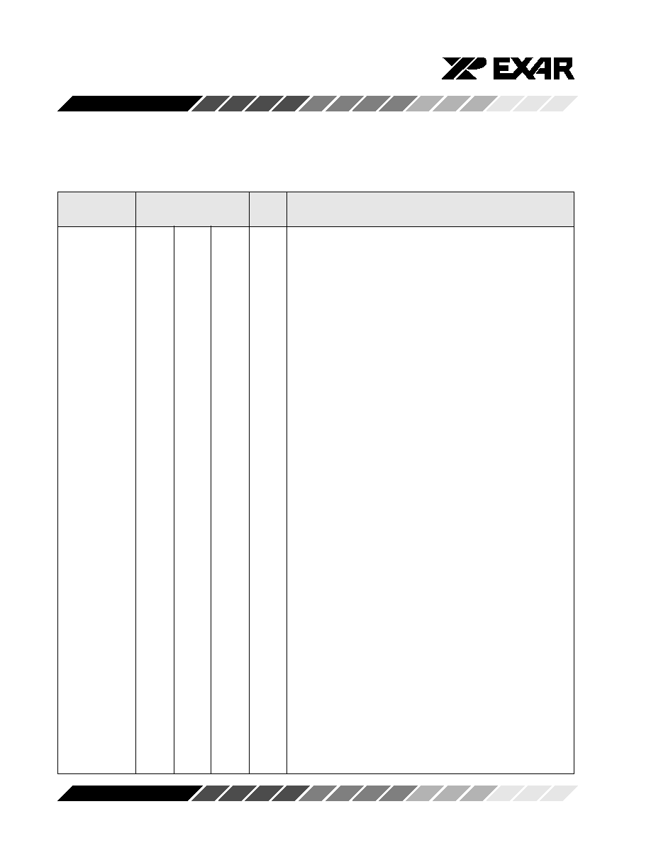
SYMBOL DESCRIPTION
A0
28
31
28
I
Address-0 Select Bit - Internal registers address selection.
A1
27
30
27
I
Address-1 Select Bit Internal registers address selection.
A2
26
29
26
I
Address-2 Select Bit Internal registers address selection.
IOR
22
25
20
I
Read strobe. Its function is the same as -IOR (see -IOR),
except it is active high. Either an active -IOR or IOR is
required to transfer data from 580 to CPU during a read
operation.
CS0
12
14
9
I
Chip Select-0. A logical 1 on this pin provides the chip select
0 function.
CS1
13
15
10
I
Chip Select-1. A logical 1 on this pin provides the chip select
1 function.
-CS2
14
16
11
I
Chip Select -2. A logical 0 on this pin provides the chip select
2 function.
IOW
19
21
17
I
Write strobe. A logic 1 transition creates a write strobe. Its
function is the same as -IOW (see -IOW), but it acts as an
active high input signal. Either -IOW or IOW is required to
transfer data from the CPU to 580 during a write operation.
-AS
25
28
24
I
Address Strobe. A logic 0 transition on -AS latches the state
of the chip selects and the register select bits, A0-A2. This
input is used when address and chip selects are not stable
for the duration of a read or write operation, i.e., a micropro-
cessor that needs to de-multiplex the address and data bits.
If not required, the -AS input can be permanently tied to a
logic 0 (it is edge triggered).
D0-D7
1-8
2-9
43-47
2-4
I/O
Data Bus (Bi-directional) - These pins are the eight bit, three
state data bus for transferring information to or from the
controlling CPU. D0 is the least significant bit and the first
data bit in a transmit or receive serial data stream.
GND
20
22
18
Pwr
Signal and Power Ground.
Symbol
Pin
Signal
Pin Description
40
44
48
type
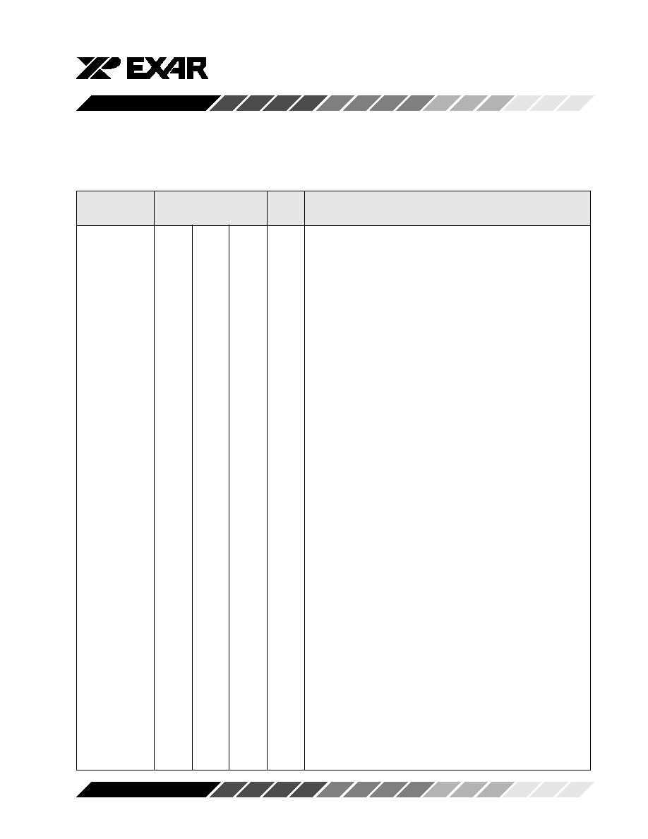
ST16C580
5
Rev. 1.20
-IOR
21
24
19
I
Read strobe (active low strobe). A logic 0 on this pin transfers
the contents of the 580 data bus to the CPU.
-IOW
18
20
16
I
Write strobe (active low strobe) - A logic 0 on this pin
transfers the contents of the CPU data bus to the addressed
internal register.
INT
30
33
30
O
Interrupt Request.
-RXRDY
29
32
29
O
Receive Ready. A logic 0 indicates receive data ready
status, i.e. the RHR is full or the FIFO has one or more RX
characters available for unloading. This pin goes to a logic
0 when the FIFO/RHR is full or when there are more
characters available in either the FIFO or RHR.
-TXRDY
24
27
23
O
Transmit Ready. Buffer ready status is indicated by a logic
0, i.e., at least one location is empty and available in the
FIFO or THR. This pin goes to a logic 1 when there are no
more empty locations in the FIFO or THR.
-BAUDOUT
15
17
12
O
Baud Rate Generator Output. This pin provides the 16X
clock of the selected data rate from the baud rate generator.
The RCLK pin must be connected externally to -BAUDOUT
when the receiver is operating at the same data rate.
-DDIS
23
26
22
O
Drive Disable. This pin goes to a logic 0 when the external
CPU is reading data from the 580. This signal can be used
to disable external transceivers or other logic functions.
-OP1
34
38
34
O
Output-1 (User Defined) - See bit-2 of modem control
register (MCR bit-2).
-OP2
31
35
31
O
Output-2 (User Defined). This pin provides the user a
general purpose output. See bit-3 modem control register
(MCR bit-3).
RCLK
9
10
5
I
Receive Clock Input. This pin is used as external 16X clock
input to the receiver section. External connection to -
Baudout pin is required in order to utilize the internal baud
rate generator.
SYMBOL DESCRIPTION
Symbol
Pin
Signal
Pin Description
40
44
48
type