RFMA1720-1W-SMP
ISSUED
07/28/2006
17.5 ≠ 20.0 GHz Power AMPLIFIER MMIC
Specifications are subject to change without notice.
Excelics Semiconductor, Inc. 310 De Guigne Drive, Sunnyvale, CA 94085
page 1 of 2
Phone: 408-737-1711 Fax: 408-737-1868 Web:
www.excelics.com
Revised July 2006
FEATURES
∑
17.5 ≠ 20.0GHz Operating Frequency Range
∑
29dBm Output Power at 1dB Compression
∑
28 dB Typical Power Gain @1dB Compression
∑
-41dBc OIMD3 @Each Tone Pout 18dBm
∑
Small Surface Mount Package
APPLICATIONS
∑
Point-to-point and point-to-multipoint radio
∑
Military Radar Systems
ELECTRICAL CHARACTERISTICS (T
B
=25
∞
C, V
D
=7V, V
G
=-5V)
SYMBOL PARAMETER/TEST
CONDITIONS MIN
TYP
MAX
UNITS
F
Operating Frequency Range
17.5
20.0
GHz
P
1dB
Output Power at 1dB Gain Compression
28
29
dBm
G
1dB
Gain @ 1dB Gain Compression
25
28
dB
OIMD3
Output 3
rd
Order Intermodulation Distortion
@f=10MHz, Each Tone Pout 18dBm
-41 -38 dBc
Input RL
Input Return Loss
-12
-8
dB
Output RL
Output Return Loss
-12
-8
dB
Idd
Drain Current
900
1080
mA
V
DD
Drain Voltage
7
8
V
V
G
Gate
Voltage
-5 V
Rth
Thermal
Resistance
9
o
C/W
MAXIMUM RATINGS AT 25∞C
1,2
SYMBOL CHARACTERISTIC
ABSOLUTE
CONTINOUS
V
DS
Drain to Source Voltage
12V
8 V
V
GS
Gate to Source Voltage
-8V
-3 V
I
DD
Drain
Current
Idss
1.9A
P
IN
Input Power
20dBm
@ 3dB compression
T
CH
Channel
Temperature
175∞C
150∞C
T
STG
Storage
Temperature
-65/175∞C
-65/150∞C
P
T
Total
Power
Dissipation
15.0W
12.6W
1. Operating the device beyond any of the above rating may result in permanent damage.
2. Bias conditions must also satisfy the following equation V
DS
*I
DS
< (T
CH
≠T
B
)/R
TH
; where T
B
= Base Plate Temperature
RFMA1720-1W-SMP
ISSUED
07/28/2006
17.5 ≠ 20.0 GHz Power AMPLIFIER MMIC
Specifications are subject to change without notice.
Excelics Semiconductor, Inc. 310 De Guigne Drive, Sunnyvale, CA 94085
page 2 of 2
Phone: 408-737-1711 Fax: 408-737-1868 Web:
www.excelics.com
Revised July 2006
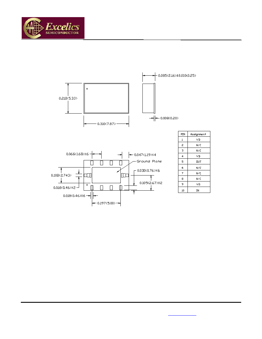
Package Dimension and Pin Assignment
9
8
7
6
4
3
2
1
5
10
10
1
2
3
4
5
6
7
8
9
EXCELICS
RFMA
1720-1W
SMP
TOP SIDE VIEW
BOTTOM SIDE VIEW
NOTES:
1.
Ground Plane Must be Soldered to PCB RF Ground.
2.
∞
Indicates PIN 1.
3.
All Dimensions are in Inches (Millimeters).
4.
All Tolerances are ±0.003 (±0.08).