Æ
BZW04-5V8........ BZW04-256
∑ Glass passivated junction
∑ Low Capacitance AC signal protection
∑ Response time typically < 1 ns.
∑ Molded case
∑ The plastic material carries
U/L recognition 94 V-0
∑ Terminals: Axial leads
Mounting instructions
1. Min. distance from body to soldering point,
4 mm.
2. Max. solder temperature, 350 ∞C.
3. Max. soldering time, 3.5 sec.
4. Do not bend lead at a point closer than
2 mm. to the body.
Maximum Ratings, according to IEC publication No. 134
Non repetitive surge peak forward current (t = 10 ms)
Operating temperature range
Storage temperature range
Steady state Power Dissipation (l = 10mm)
P
pp
I
FSM
T
j
T
stg
P
M(AV)
400 W
50 A
≠ 65 to + 175 ∞C
≠ 65 to + 175 ∞C
1 W
Electrical Characteristics at Tamb = 25 ∞C
V
F
Max. forward voltage
drop at I
F
= 50 A
R
thj-l
Max. thermal resistance (1 = 10 mm.)
V
BR
220 V
V
BR
> 220 V
45 ∞C/W
400W Unidirectional and Bidirectional Transient Voltage Suppressor Diodes
Dimensions in mm.
DO-15
(Plastic)
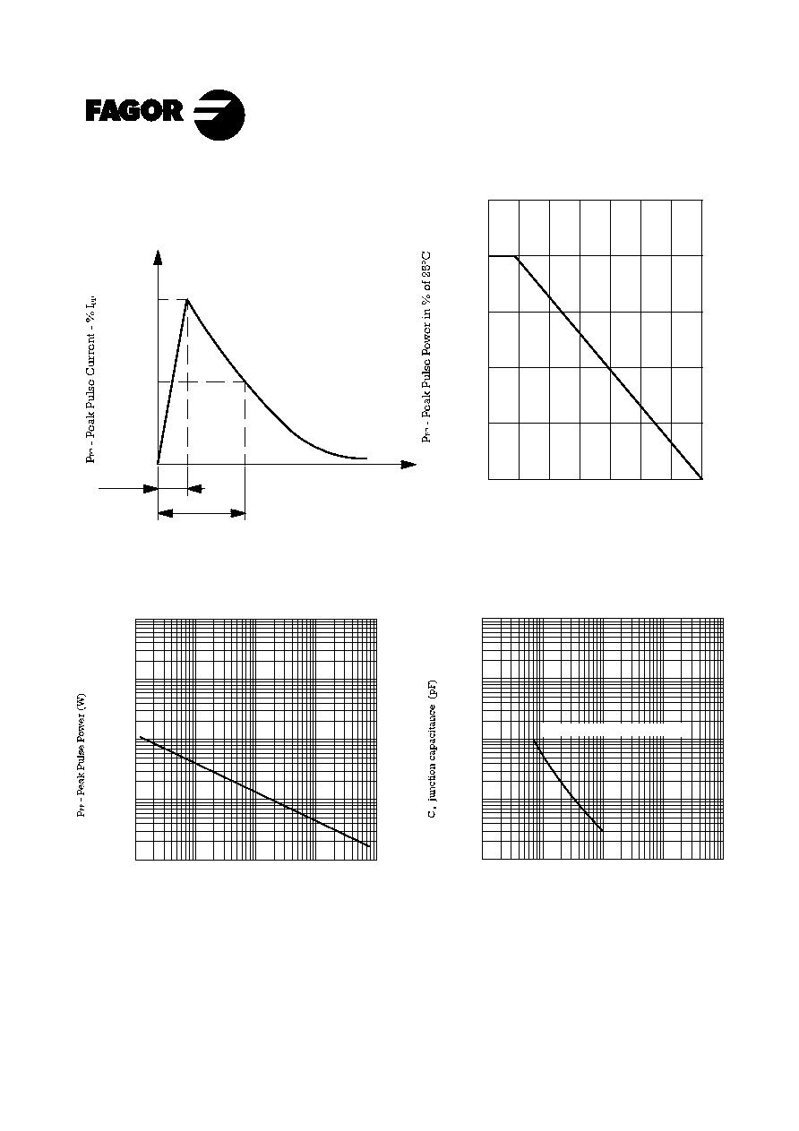
Peak Pulse
Power Rating
At 1 ms. Exp.
400 W
Reverse
stand-off
Voltage
5.8 ˜ 256 V
58.5 min.
± 0.2
6.35
BZW04-6V4B.... BZW04-256B
∑ Polarity: Color band denotes
Cathode except bidirectional types
(Note 1)
Note 1: Valid only for Unidirectional.
3.5 V
5.0 V
(Note 1)
Peak pulse power with 10/1000 µs
exponential pulse
Jan - 00